
Why Ammeters Go in Series and Voltmeters in Parallel
Learn how ammeters and voltmeters work, why their placement matters, and how to avoid common circuit measurement mistakes in HSC Physics.
Most students make the same circuit mistake: they see an ammeter and voltmeter as just two types of “measuring devices” and place them wherever there is space. Then a circuit that looks reasonable gives a strange reading, or worse, an ammeter connected across a battery creates a huge current.
The pattern usually looks like this:
- “The voltmeter measures voltage, so I’ll put it where the current goes.”
- “The ammeter measures current, so I’ll put it across the component I’m interested in.”
Both ideas feel logical. Both are wrong.
The fix is to stop memorising “ammeter = series” and “voltmeter = parallel” as a rule. Instead, ask:
What does this instrument need to measure, and what resistance must it have to avoid disturbing the circuit?
That question works even when the circuit diagram is unfamiliar.
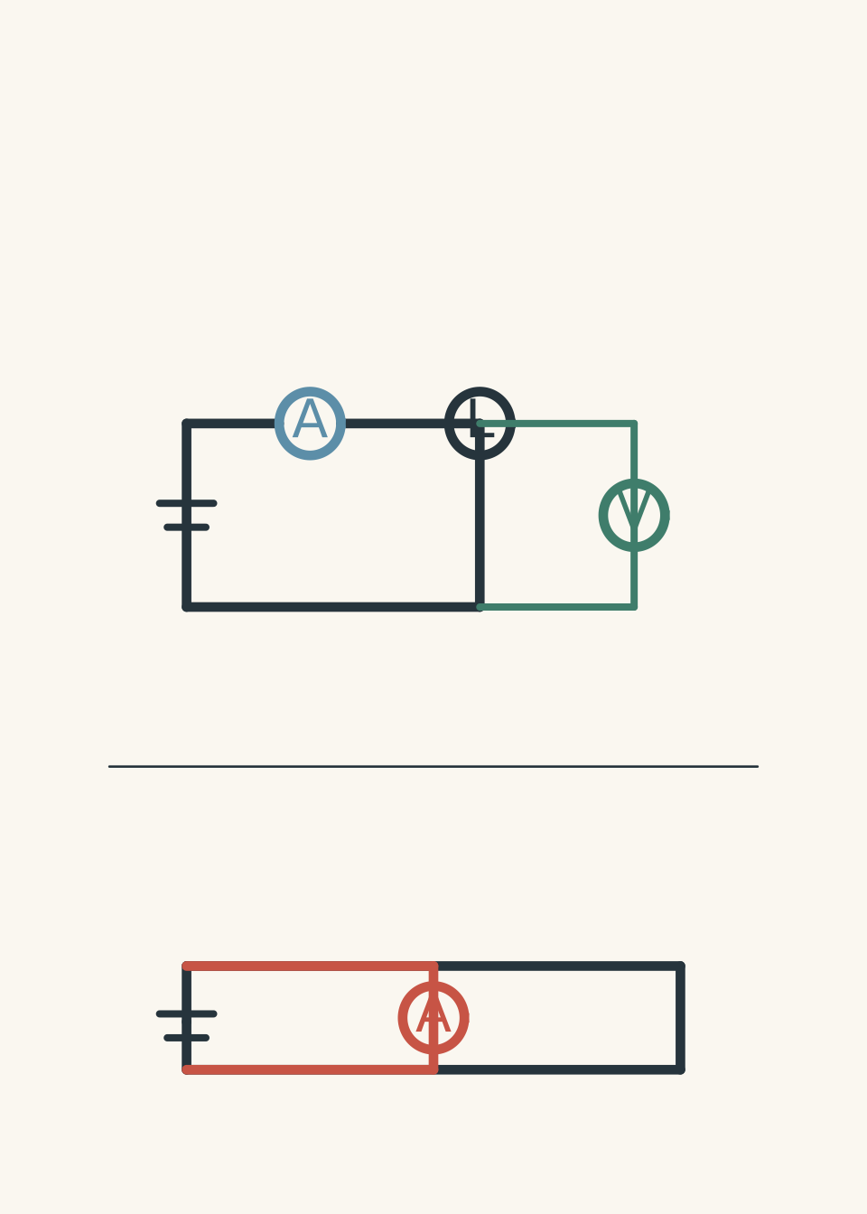
01The mistake: treating meters like ordinary components
Imagine you are trying to measure traffic on a road.
An ammeter is like a traffic counter placed on the road. Every car must pass through the counter so it can measure the flow.
A voltmeter is like a height measurement taken between two points, such as measuring the height difference between the top and bottom of a hill. It does not need the whole flow of people or cars to pass through it. It only compares two locations.
That gives us the first prediction:
- If you want to measure current, should the meter interrupt the path so charge must pass through it?
- If you want to measure voltage, should the meter compare two points?
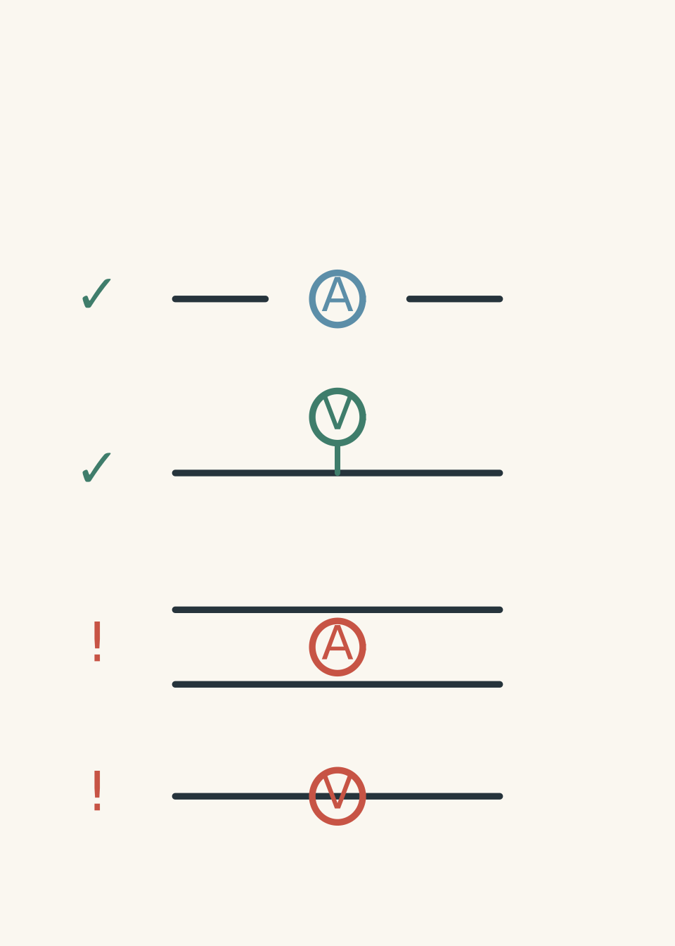
Yes. An ammeter must be placed in the path of the current. A voltmeter must be connected between two points in the circuit.
But this picture is still incomplete. The reason comes from the resistance inside the meters.
02What an ammeter actually measures
Electric current is the rate at which charge flows through a point.
\[ I = \frac{Q}{t} \]
where:
- \(I\) is current in amperes (A),
- \(Q\) is charge in coulombs (C),
- \(t\) is time in seconds (s).
To measure the current through a lamp, the ammeter must have the same current flowing through it as the lamp.
So the ammeter is inserted into the circuit path.
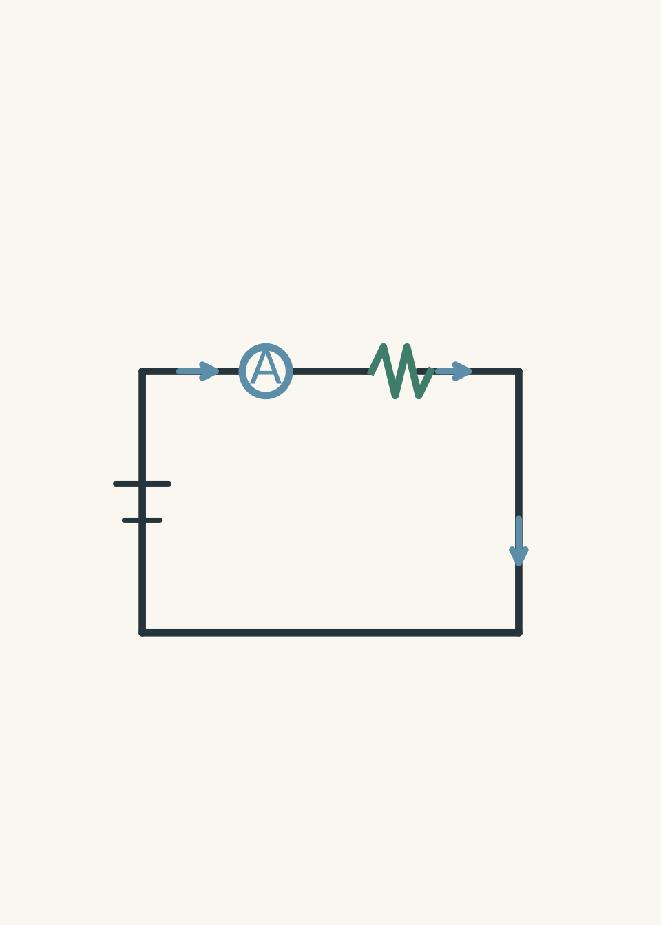
But there is a catch. Every real component has resistance. The ammeter itself slightly resists the flow of charge.
If the ammeter had a large resistance, it would reduce the current it is trying to measure.
Think of the traffic counter again. If the counter is a narrow gate, it changes the traffic flow. A good counter should be like a wide-open road section that barely affects the traffic.
So an ideal ammeter has:
\[ R_A = 0 \ \Omega \]
where \(R_A\) is the resistance of the ammeter.
Real ammeters have a very small resistance, close to zero.
03Why an ammeter across a battery is dangerous
A common mistake is connecting an ammeter directly across the terminals of a power supply.
A student might think:
“The battery has a voltage, and the ammeter measures current, so putting it across the battery should show the battery current.”
The problem is that the ammeter is designed to have almost no resistance.
Using Ohm’s law:
\[ V = IR \]
or
\[ I = \frac{V}{R} \]
Suppose a \(9.0\text{ V}\) battery is connected directly across an ammeter with resistance \(0.10\Omega\).
\[ I = \frac{9.0}{0.10} \]
\[ I = 90\text{ A} \]
That is a very large current compared with what most school circuits are designed to handle.
The ammeter has accidentally created a low-resistance path. Instead of the circuit controlling the current, the meter becomes the easiest route for charge to move.
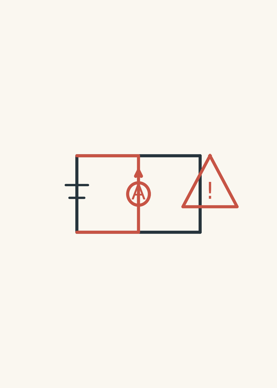
The rule is therefore not simply “never put an ammeter in parallel”.
The deeper rule is:
An ammeter should only be placed where the current you want to measure is already flowing through a component or branch.
04What a voltmeter actually measures
Voltage is the difference in electrical potential energy per unit charge between two points.
\[ V = \frac{W}{Q} \]
where:
- \(V\) is potential difference in volts (V),
- \(W\) is energy transferred in joules (J),
- \(Q\) is charge in coulombs (C).
A voltmeter measures the difference between two locations.
For example, if you want the voltage across a lamp, the voltmeter must connect to both sides of the lamp.
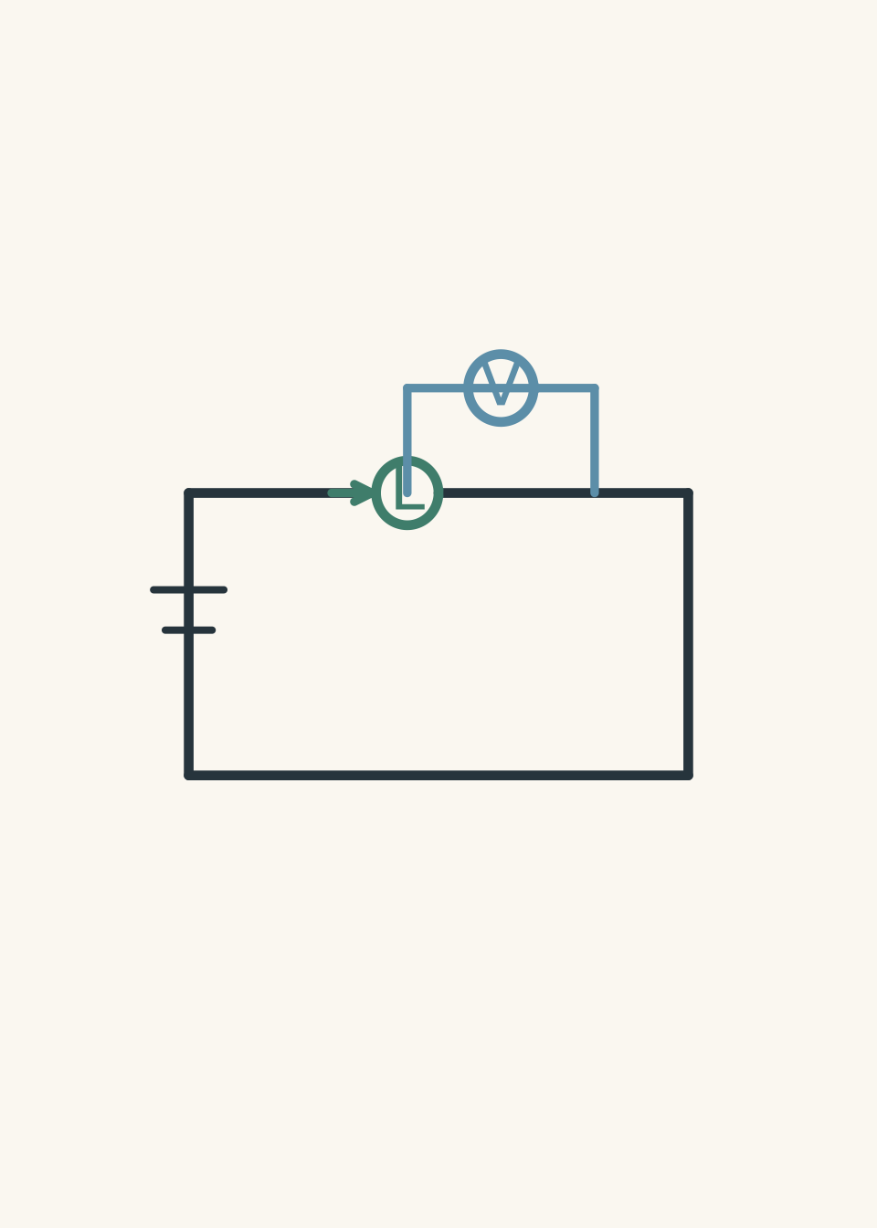
The voltmeter does not need the main current to pass through it. In fact, it should draw almost no current.
That means the ideal voltmeter has:
\[ R_V = \infty \ \Omega \]
where \(R_V\) is the resistance of the voltmeter.
A real voltmeter has a very large resistance.
Why?
Imagine measuring the temperature of a cup of tea. A thermometer with a huge metal block attached would change the temperature while measuring it. A good thermometer affects the system as little as possible.
A voltmeter should behave the same way. It should observe the voltage without significantly changing the circuit.
05The decision method for exam circuits
When you see an unfamiliar circuit diagram, use this sequence.
Step 1: Identify what the meter is trying to measure
Ask:
- Is it measuring the flow through a component? → current.
- Is it measuring the energy difference between two points? → voltage.
Step 2: Look at the connection
For an ammeter:
- The meter must be in the same path as the component.
- The current entering the component should also enter the ammeter.
For a voltmeter:
- The meter must connect across the component.
- The two terminals must touch the two points where the voltage is being compared.
Step 3: Check the resistance idea
Ask:
“Would this meter placement make the meter significantly change the circuit?”
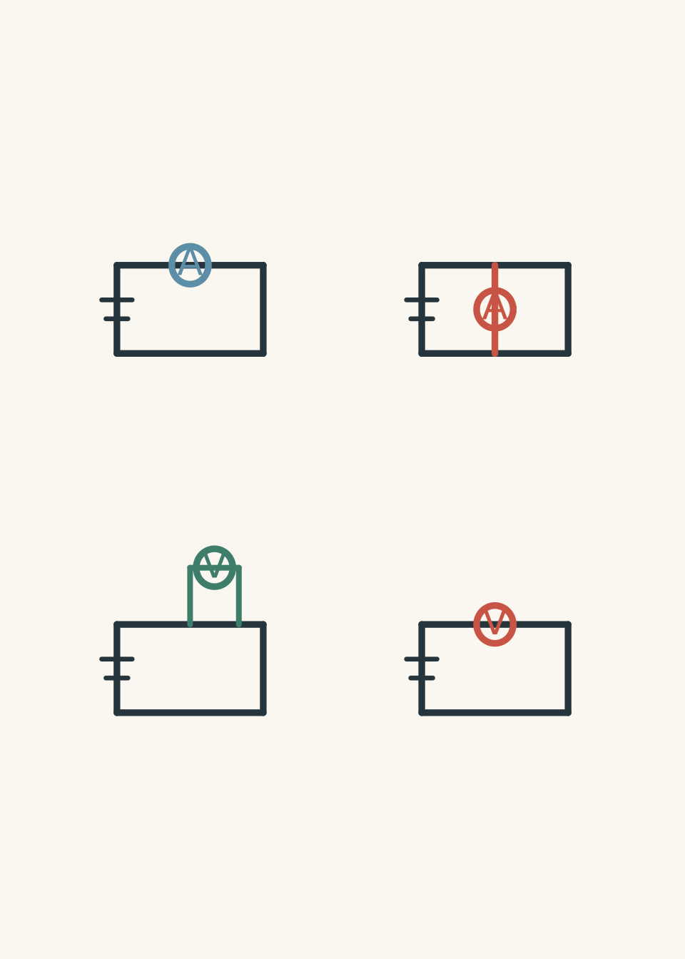
A correct setup:
- ammeter → very low resistance in series,
- voltmeter → very high resistance in parallel.
An incorrect setup often creates the opposite:
- ammeter across a power supply → almost a short circuit,
- voltmeter in series → blocks most of the current.
06The wrong shortcut and the corrected thinking
A memorised shortcut says:
“Ammeters go in series. Voltmeters go in parallel.”
That shortcut works until a question changes the wording.
For example:
“An ammeter is connected in parallel with a resistor. Explain the effect.”
A student who only memorised the rule may say:
“The ammeter is wrong because ammeters should be in series.”
That is incomplete.
The better explanation is:
“The ammeter has very low resistance, so placing it in parallel creates a low-resistance branch. Most current takes that path, producing a very large current that may damage the meter.”
The reason matters because exam questions often test the consequence, not the rule.
07Worked example: Choosing meter placement
A student wants to measure the current through a \(6.0\Omega\) resistor in a simple circuit. Should the ammeter be connected across the resistor or inserted into the same branch as the resistor?
Step 1
The question asks for current through the resistor. Current is the flow of charge through a component.
Step 2
The ammeter must experience the same current as the resistor, so it must be placed in the same branch.
Step 3
Connecting the ammeter across the resistor would create a very low-resistance path around the resistor. Most current would bypass the resistor.
Conclusion: The ammeter must be connected in series with the \(6.0\Omega\) resistor.
The important idea is not the word “series”. The important idea is that the ammeter must measure the same current by allowing that current to pass through it.
08Worked example: Explaining why a voltmeter changes the circuit less
A \(12\text{ V}\) battery is connected to a \(24\Omega\) resistor. A voltmeter with resistance \(100000\Omega\) is connected across the resistor. Explain why the voltmeter does not significantly change the circuit.
Step 1
The voltmeter measures the potential difference across the resistor, so it must be connected in parallel.
Step 2
The resistor has:
\[ R = 24\Omega \]
The voltmeter has:
\[ R_V = 100000\Omega \]
The voltmeter resistance is much larger.
Step 3
Using Ohm’s law:
\[ I = \frac{V}{R} \]
\[ I_V = \frac{12}{100000} \]
\[ I_V = 1.2 \times 10^{-4}\text{ A} \]
\[ I_V = 0.00012\text{ A} \]
Step 4
The voltmeter draws only \(0.00012\text{ A}\), which is tiny compared with the current through the resistor:
\[ I_R = \frac{12}{24} \]
\[ I_R = 0.50\text{ A} \]
Conclusion: The voltmeter has a negligible effect because its very large resistance allows almost no current to flow through it.
09Common wording changes that break memorised rules
“Measure the voltage of the battery”
A voltmeter goes across the battery terminals, not into the circuit path.
Why? The meter is comparing the potential at the positive and negative terminals.
“Measure the current supplied by the battery”
An ammeter must be placed in the path leaving or returning to the battery.
Why? The current supplied by the battery is a flow through a branch, not a difference between two points.
“The meter has non-ideal resistance”
Now the meter itself becomes part of the circuit.
A real ammeter slightly reduces current because it adds resistance.
A real voltmeter slightly increases current because it creates an additional parallel branch.
10A visual checklist for unfamiliar circuits
Before accepting a measurement setup, run this quick scan:
| Question | Correct answer |
|---|---|
| What is being measured? | Current = flow, voltage = difference between two points |
| Is the ammeter in the same path as the measured component? | Yes |
| Is the voltmeter connected across the measured component? | Yes |
| Would the ammeter create a very low resistance path? | No |
| Would the voltmeter draw a noticeable current? | No |
| Does the meter placement change the circuit dramatically? | No |
11Questions and solutions
Question 1
A student wants to measure the current through a lamp in a circuit containing a battery, a switch, and the lamp. Where should the ammeter be connected?
Solution 1
The ammeter should be connected in series with the lamp. Current is the flow of charge through the lamp, so the same current must pass through the ammeter. If the ammeter were connected across the lamp, its low resistance would create a shortcut path and change the circuit.
Question 2
A voltmeter is accidentally placed in series with a lamp. The lamp becomes much dimmer. Explain why.
Solution 2
The lamp becomes dimmer because the voltmeter has a very large resistance, which greatly reduces the current in the circuit. A student might think a voltmeter “adds voltage” because it measures voltage, but the instrument is actually a high-resistance component in this arrangement. The large resistance limits current, so the lamp receives less power.
Question 3
A \(6.0\text{ V}\) battery is connected directly across an ammeter with resistance \(0.20\Omega\). Calculate the current and explain why this connection is unsuitable.
Solution 3
The current is \(30\text{ A}\), and the connection is unsuitable because the ammeter creates a low-resistance path across the battery.
Using Ohm’s law:
\[ I = \frac{V}{R} \]
Substitute:
\[ I = \frac{6.0}{0.20} \]
\[ I = 30\text{ A} \]
A normal measuring circuit would usually have much smaller currents. The large current occurs because the ammeter resistance is close to zero, so connecting it across the supply behaves almost like a short circuit.
Question 4
A student says:
“Because a voltmeter measures voltage, it should be placed at the point where the current enters a resistor.”
Explain the mistake and describe the correct placement.
Solution 4
The mistake is confusing current measurement with voltage measurement. Voltage is not measured at a single point where current enters; it is a comparison between two points.
The correct placement is across the resistor, with one voltmeter terminal connected to each end of the resistor. This allows the voltmeter to compare the electrical potential difference across the component while its large resistance keeps its own current very small.
Question 5
A circuit contains a battery and two identical resistors connected in parallel. A student places an ideal ammeter across one resistor and predicts:
“The ammeter will measure the current through that resistor.”
Explain why this prediction is wrong, and determine what happens to the circuit in the ideal case.
Solution 5
The prediction is wrong because the ammeter does not measure the resistor current in this arrangement; it replaces the resistor branch with a zero-resistance path.
An ideal ammeter has:
\[ R_A = 0\Omega \]
The student is imagining the ammeter as a harmless observer, but a parallel connection makes it part of the circuit. The current will choose the path with zero resistance rather than flowing through the resistor.
In the ideal case, the ammeter creates a short circuit across the resistor. The voltage across that resistor becomes:
\[ V_R = 0\text{ V} \]
because both ends of the resistor are effectively connected to the same potential. The current through the resistor becomes:
\[ I_R = \frac{V_R}{R} \]
\[ I_R = \frac{0}{R} \]
\[ I_R = 0\text{ A} \]
The tempting route is to think “the ammeter measures current, so it must show the resistor current”. The hidden constraint is that the meter’s resistance changes the circuit. An ammeter only measures a current that is already flowing through its path; it does not magically detect current elsewhere.
A useful next step is applying the same resistance logic to internal resistance, terminal voltage, and why real batteries do not always behave like perfect voltage sources.