
Year 12 Physics Electromagnetism: 90-Mark Practice Exam
Test your understanding of the Year 12 Physics 2025 Electromagnetism content with this original 90-mark timed practice paper. Includes exam instructions, 15 questions, fully worked solutions, and a detailed marking guide across the supplied syllabus scope.
This is an original tutorgum practice paper for mixed revision of the supplied Year 12 Physics 2025 Electromagnetism content. It is a topic-area revision paper, not a full-course Physics examination, and it is not an official, endorsed, past, or predicted NESA paper.
The assessment covers electric and magnetic forces, charged-particle motion, the motor effect and torque, DC and AC motors and generators, electromagnetic induction, transformers, and magnetic braking. It assesses only the supplied syllabus scope and does not combine content from other syllabus editions.
01Exam instructions
- Suggested reading time: 5 minutes.
- Suggested working time: 110 minutes.
- Total marks: 90.
- Equipment: Scientific calculator, ruler, and writing materials. No notes or internet resources.
- Constants:
- Elementary charge magnitude: \(e=1.60\times10^{-19}\ \mathrm{C}\)
- Electron mass: \(m_e=9.11\times10^{-31}\ \mathrm{kg}\)
- Use \(\pi=3.142\) where needed.
- Use SI units throughout. Give numerical answers to 2-3 significant figures unless otherwise appropriate.
- Show working for calculations, include units, and explain the physical reasoning behind your answers.
- Assume uniform fields within the specified regions, neglect relativistic effects, and ignore edge effects where instructed. Use ideal transformer relationships only when a question explicitly specifies an ideal transformer.
- All questions are compulsory. The time and equipment conditions are suggested conditions for this practice paper, not claims about official examination rules.
02Questions
Question 1 (8 marks)
A singly charged positive ion has a mass of \(3.2\times10^{-26}\ \mathrm{kg}\). It starts from rest between two parallel plates with a potential difference of \(600\ \mathrm{V}\) and a separation of \(3.0\ \mathrm{cm}\). The ion moves in the direction of the electric force and crosses the full potential difference.
(a) Calculate the magnitude of the electric field between the plates. State one limitation of treating this field as uniform. (3 marks)
(b) Calculate the magnitude of the electric force on the ion and its acceleration. (2 marks)
(c) Calculate the work done by the electric field and the final speed of the ion. Show how the work expression can also be written in terms of electric field strength and plate separation. (3 marks)
Question 2 (8 marks)
An electron gun accelerates electrons from rest through a potential difference of \(1.0\ \mathrm{kV}\). Ignore relativistic effects.
(a) Calculate the speed of an electron as it leaves the accelerating region. (2 marks)
An electron then enters horizontally between parallel plates at a horizontal speed of \(1.9\times10^7\ \mathrm{m\,s^{-1}}\). The plates are \(0.060\ \mathrm{m}\) long. A uniform electric field of \(1.5\times10^3\ \mathrm{N\,C^{-1}}\) acts vertically upwards. Ignore edge effects.
(b) Calculate the time the electron spends between the plates and its vertical deflection. State the direction of deflection and explain why the motion resembles projectile motion. (4 marks)
(c) Compare the effects of electric and magnetic fields on a stationary charged particle. Explain how their abilities to transfer energy to a moving charged particle differ. (2 marks)
Question 3 (7 marks)
A positive ion has charge \(q=+3.2\times10^{-19}\ \mathrm{C}\) and mass \(m=6.4\times10^{-27}\ \mathrm{kg}\).
(a) In one setup, the ion moves at \(2.5\times10^6\ \mathrm{m\,s^{-1}}\), travelling \(30^\circ\) east of north. A uniform magnetic field of \(0.40\ \mathrm{T}\) points north. Calculate the magnetic force magnitude and state its direction. (2 marks)
(b) In a separate setup, the ion enters a uniform magnetic field of \(0.40\ \mathrm{T}\) with its velocity perpendicular to the field. Its speed is unchanged. Derive an expression for the radius of its circular path and calculate the radius. (3 marks)
(c) Derive an expression for the period of the ion’s circular motion and calculate the period. (2 marks)
Question 4 (5 marks)
A mass spectrometer separates two types of singly charged positive ions. Both ions start from rest and are accelerated through a potential difference of \(1.0\ \mathrm{kV}\). They then enter a uniform magnetic field of \(0.25\ \mathrm{T}\), perpendicular to their velocities.
Their masses are:
- Ion 1: \(3.2\times10^{-26}\ \mathrm{kg}\)
- Ion 2: \(3.6\times10^{-26}\ \mathrm{kg}\)
Assume both ions have charge \(+e\).
(a) Calculate the speed of Ion 1 after acceleration. (2 marks)
(b) Calculate the radius of the circular path for each ion in the magnetic field. (2 marks)
(c) Identify which ion follows the path with the larger radius and explain how this allows the spectrometer to distinguish the ions. (1 mark)
Question 5 (5 marks)
A straight wire has a total length of \(0.80\ \mathrm{m}\), of which \(0.20\ \mathrm{m}\) lies within a uniform magnetic field of \(0.45\ \mathrm{T}\). The wire carries a current of \(4.0\ \mathrm{A}\). The angle between the conventional current direction and the magnetic field is \(30^\circ\).
(a) Calculate the magnitude of the magnetic force on the wire. (2 marks)
(b) Calculate the maximum possible force on the active wire segment. State the angle between the current and magnetic field for maximum force, and the angle for zero force. (2 marks)
(c) In a separate setup, conventional current flows east while the magnetic field points north. State the direction of the force on the active conductor. (1 mark)
Question 6 (6 marks)
(a) A force of \(20\ \mathrm{N}\) acts on a spanner \(0.30\ \mathrm{m}\) from its pivot. The angle between the spanner and the force is \(60^\circ\). Calculate the magnitude of the torque about the pivot. (2 marks)
(b) A rectangular coil in a motor has 60 turns, a current of \(0.40\ \mathrm{A}\), an area of \(3.0\times10^{-3}\ \mathrm{m^2}\), and a magnetic field strength of \(0.25\ \mathrm{T}\). The angle between the coil’s normal and the magnetic field is \(90^\circ\). Calculate the torque magnitude on the coil. (2 marks)
(c) Define the moment arm of a force and explain why applying the same force farther from a pivot generally produces a greater torque. (2 marks)
Question 7 (10 marks)
(a) Describe the roles of the coil, permanent magnets, split-ring commutator, and brushes in a simple DC motor. (4 marks)
(b) A DC motor is connected to a \(12\ \mathrm{V}\) supply. Its coil has a resistance of \(3.0\ \Omega\).
At start-up, the back emf is negligible. At its operating speed, the back emf is \(9.0\ \mathrm{V}\).
Calculate the current at start-up and at operating speed. Explain the origin of back emf and how changes in motor speed affect current and energy conversion. (4 marks)
(c) Describe how a brushless DC motor uses electronic control to produce rotation. Identify one difference between its construction or operation and that of a simple brushed DC motor. (2 marks)
Question 8 (5 marks)
A generator contains a coil of \(N\) turns rotating at constant angular speed in a uniform magnetic field.
(a) Explain why the induced emf is sinusoidal and describe the role of slip rings in an AC generator. (3 marks)
(b) Explain how a DC generator produces a direct-current output. Include the roles of the split-ring commutator and brushes. (2 marks)
Question 9 (6 marks)
A three-phase AC induction motor contains stationary stator windings and a conductive squirrel-cage rotor. The rotor consists of conducting bars joined by end rings.
(a) Describe the roles of the stator windings and the conducting rotor. (2 marks)
(b) Explain how the motor produces rotation. Your answer must account for the rotating magnetic field, induced rotor currents, electromagnetic torque, and why the rotor runs below synchronous speed. (4 marks)
Question 10 (7 marks)
A 150-turn coil has an area of \(1.5\times10^{-3}\ \mathrm{m^2}\). It is placed in a uniform magnetic field of \(0.40\ \mathrm{T}\). The angle between the magnetic field and the normal to the coil is \(60^\circ\).
(a) Calculate the magnetic flux through one turn. State one way this flux could be changed. (3 marks)
(b) The flux through each turn changes from \(3.0\times10^{-4}\ \mathrm{Wb}\) to \(0.5\times10^{-4}\ \mathrm{Wb}\) over \(0.025\ \mathrm{s}\). Calculate the magnitude of the average induced emf in the coil. (2 marks)
(c) A north pole of a magnet approaches a coil. An observer looks at the coil from the magnet’s side. Use Lenz’s law to determine the induced current direction as seen by the observer. Also state the general condition required for induction when a magnet moves relative to a coil or a conductor moves through a magnetic field. (2 marks)
Question 11 (4 marks)
Two electrically separate solenoids share a soft-iron core. The primary solenoid is connected to a supply whose current can change, while the secondary solenoid is connected to a measuring device.
(a) Explain why an emf can be induced in the secondary solenoid when the primary current changes, even though the solenoids are not electrically connected. (2 marks)
(b) When the primary current increases, state what the magnetic effect of the induced secondary current must oppose. (1 mark)
(c) State one way to increase the magnitude of the induced emf in the secondary solenoid. (1 mark)
Question 12 (7 marks)
Two ideal transformers have a primary voltage of \(240\ \mathrm{V}\) and 900 turns in the primary winding.
- Transformer A has 135 turns in its secondary winding.
- Transformer B has 1800 turns in its secondary winding.
(a) Calculate the secondary voltage of each transformer and identify each as step-up or step-down. (3 marks)
(b) The primary current in Transformer A is \(0.40\ \mathrm{A}\). Calculate its input power and secondary current. (3 marks)
(c) State how energy conservation in an ideal transformer explains the relationship between voltage and current. (1 mark)
Question 13 (6 marks)
(a) A transformer winding has a resistance of \(0.80\ \Omega\) and carries a current of \(2.0\ \mathrm{A}\). Calculate its resistive heating loss and suggest one practical way to reduce winding losses. (2 marks)
(b) Explain how eddy currents form in a transformer core and why a laminated core reduces these losses. (2 marks)
(c) Define leakage flux in a transformer and describe one way to improve magnetic coupling between its windings. (2 marks)
Question 14 (3 marks)
A conducting metal plate moves into and out of a region of magnetic field. Its motion causes the magnetic flux through loops within the plate to change.
(a) Explain how induced eddy currents produce a braking force on the moving plate. (2 marks)
(b) State what happens to the plate’s kinetic energy as it is braked, in accordance with conservation of energy. (1 mark)
Question 15 (3 marks)
An actual transformer has the following measured values:
- Primary voltage: \(240\ \mathrm{V}\)
- Primary current: \(0.50\ \mathrm{A}\)
- Secondary voltage: \(24\ \mathrm{V}\)
- Secondary current: \(4.0\ \mathrm{A}\)
(a) Calculate the input power. (1 mark)
(b) Calculate the output power. (1 mark)
(c) Calculate the transformer’s efficiency as a percentage. (1 mark)
03Worked solutions and marking guide
Solution 1
(a) Electric field strength and model limitation
The electric field strength \(E\) is the potential difference \(V\) divided by the plate separation \(d\). Here, \(E\) is measured in \(\mathrm{V\,m^{-1}}\), \(V\) in volts, and \(d\) in metres.
Convert the separation:
\[ d=3.0\ \mathrm{cm}=0.030\ \mathrm{m} \]
Then:
\[ \begin{aligned} E&=\frac{V}{d}\\ &=\frac{600}{0.030}\\ &=2.0\times10^4\ \mathrm{V\,m^{-1}}. \end{aligned} \]
The field is approximately uniform in the central region between the plates. Near the edges, fringing makes the field nonuniform, so the simple uniform-field model becomes less accurate.
Marking:
- 1 mark for the correct field relationship and conversion to metres.
- 1 mark for the field strength with units.
- 1 mark for identifying the limitation near the plate edges.
(b) Electric force and acceleration
The ion carries one positive elementary charge, so \(q=+1.60\times10^{-19}\ \mathrm{C}\).
The magnitude of the electric force is:
\[ \begin{aligned} F&=qE\\ &=(1.60\times10^{-19})(2.0\times10^4)\\ &=3.2\times10^{-15}\ \mathrm{N}. \end{aligned} \]
Using Newton’s second law, \(F=ma\), where \(m\) is mass and \(a\) is acceleration:
\[ \begin{aligned} a&=\frac{F}{m}\\ &=\frac{3.2\times10^{-15}}{3.2\times10^{-26}}\\ &=1.0\times10^{11}\ \mathrm{m\,s^{-2}}. \end{aligned} \]
Marking:
- 1 mark for the force magnitude.
- 1 mark for the acceleration magnitude.
(c) Work, energy, and final speed
For a charge moving through a potential difference \(V\), the work done by the electric field is \(W=qV\). In a uniform field, \(V=Ed\), so the same work can be written as \(W=qEd\).
\[ W=qV=qEd \]
Using the potential difference:
\[ \begin{aligned} W&=(1.60\times10^{-19})(600)\\ &=9.6\times10^{-17}\ \mathrm{J}. \end{aligned} \]
Using the field strength and distance gives the same result:
\[ \begin{aligned} W&=(1.60\times10^{-19})(2.0\times10^4)(0.030)\\ &=9.6\times10^{-17}\ \mathrm{J}. \end{aligned} \]
The ion starts from rest, so its initial kinetic energy is zero. Assuming no other energy transfers, the work done by the field becomes kinetic energy:
\[ W=\Delta K=\frac12 mv^2. \]
Rearranging for final speed \(v\):
\[ \begin{aligned} v&=\sqrt{\frac{2W}{m}}\\ &=\sqrt{\frac{2(9.6\times10^{-17})}{3.2\times10^{-26}}}\\ &=7.7\times10^4\ \mathrm{m\,s^{-1}}. \end{aligned} \]
Marking:
- 1 mark for calculating the work done.
- 1 mark for connecting \(W=qV=qEd\) with the kinetic energy gained.
- 1 mark for the final speed with units.
Solution 2
(a) Electron gun
The electron gains kinetic energy as it moves through the accelerating potential difference. For a non-relativistic electron starting from rest:
\[ eV=\frac12 m_e v^2. \]
Here, \(e\) is the elementary charge magnitude, \(m_e\) is the electron mass, and \(v\) is the final speed.
Rearranging:
\[ v=\sqrt{\frac{2eV}{m_e}}. \]
Substituting \(V=1000\ \mathrm{V}\):
\[ \begin{aligned} v&=\sqrt{\frac{2(1.60\times10^{-19})(1000)} {9.11\times10^{-31}}}\\ &=1.87\times10^7\ \mathrm{m\,s^{-1}}. \end{aligned} \]
Marking:
- 1 mark for relating electrical work to kinetic energy.
- 1 mark for the calculated speed.
(b) Deflection between parallel plates
The horizontal speed is approximately constant because the electric force acts vertically, not horizontally.
The time between the plates is:
\[ \begin{aligned} t&=\frac{L}{v_x}\\ &=\frac{0.060}{1.9\times10^7}\\ &=3.2\times10^{-9}\ \mathrm{s}. \end{aligned} \]
Here, \(L\) is the plate length and \(v_x\) is the horizontal velocity component.
The electric field points upwards, but the electron is negatively charged. Its force and acceleration therefore point downwards.
The acceleration magnitude is:
\[ \begin{aligned} a_y&=\frac{eE}{m_e}\\ &=\frac{(1.60\times10^{-19})(1.5\times10^3)} {9.11\times10^{-31}}\\ &=2.6\times10^{14}\ \mathrm{m\,s^{-2}}. \end{aligned} \]
The vertical displacement \(y\), measured from the entry position, is:
\[ \begin{aligned} y&=\frac12 a_y t^2\\ &=\frac12(2.6\times10^{14})(3.2\times10^{-9})^2\\ &=1.3\times10^{-3}\ \mathrm{m}. \end{aligned} \]
The electron is deflected approximately \(1.3\ \mathrm{mm}\) downwards.
This resembles projectile motion because the horizontal velocity remains approximately constant while a constant vertical acceleration changes the vertical velocity. The difference is that the acceleration comes from an electric force, rather than gravity. Within the uniform field, the trajectory is parabolic.
Marking:
- 1 mark for the time between the plates.
- 1 mark for the vertical acceleration.
- 1 mark for the displacement magnitude and direction.
- 1 mark for the projectile-motion comparison.
(c) Electric fields versus magnetic fields
An electric field can exert a force on a stationary charged particle because the electric force is \(F_E=qE\). A magnetic field cannot exert a magnetic force on a stationary charge because the magnetic force depends on velocity.
For a moving charge, the magnetic force is perpendicular to its velocity. It changes the direction of motion but does no work, so it does not change the particle’s kinetic energy. An electric field can transfer energy to a charge when the force has a component along its displacement.
Marking:
- 1 mark for distinguishing their effects on a stationary charge.
- 1 mark for explaining the difference in energy transfer.
Electric fields vs magnetic fields
| Electric field | F = qE Exerts force on stationary or moving charges. Can transfer energy and change speed. |
|---|---|
| Magnetic field | F = qvB sin θ Exerts force only on moving charges. Force changes direction, not speed or kinetic energy. |
Solution 3
(a) Force on a moving charge
The magnetic force magnitude is:
\[ F=qvB\sin\theta, \]
where \(q\) is charge, \(v\) is speed, \(B\) is magnetic field strength, and \(\theta\) is the angle between velocity and magnetic field.
Here, \(\theta=30^\circ\).
\[ \begin{aligned} F&=(3.2\times10^{-19})(2.5\times10^6)(0.40) \sin30^\circ\\ &=1.6\times10^{-13}\ \mathrm{N}. \end{aligned} \]
For direction, use the motor-effect direction rule for a positive charge. The ion’s eastward velocity component crossed with the northward field gives a force out of the page.
Marking:
- 1 mark for the force magnitude.
- 1 mark for the correct direction.
(b) Radius of circular motion
When the velocity is perpendicular to the field, the magnetic force has its maximum magnitude and acts perpendicular to the motion. It provides the centripetal force needed for circular motion.
The magnetic force is \(qvB\), and the centripetal force is \(mv^2/r\), where \(r\) is the radius.
Equating them:
\[ qvB=\frac{mv^2}{r}. \]
Cancel one factor of \(v\) and rearrange:
\[ r=\frac{mv}{qB}. \]
Substitute the given values:
\[ \begin{aligned} r&=\frac{(6.4\times10^{-27})(2.5\times10^6)} {(3.2\times10^{-19})(0.40)}\\ &=0.125\ \mathrm{m}. \end{aligned} \]
Marking:
- 1 mark for equating magnetic and centripetal forces.
- 1 mark for deriving the radius expression.
- 1 mark for the calculated radius.
(c) Period of circular motion
The period \(T\) is the time taken for one complete revolution. For circular motion:
\[ T=\frac{2\pi r}{v}. \]
Substitute \(r=mv/(qB)\):
\[ T=\frac{2\pi}{v}\left(\frac{mv}{qB}\right) =\frac{2\pi m}{qB}. \]
The speed cancels, so the period is independent of speed under these conditions.
\[ \begin{aligned} T&=\frac{2\pi(6.4\times10^{-27})} {(3.2\times10^{-19})(0.40)}\\ &=3.14\times10^{-7}\ \mathrm{s}. \end{aligned} \]
Marking:
- 1 mark for deriving the period expression.
- 1 mark for the calculated period.
Solution 4
(a) Speed of Ion 1
The ions gain kinetic energy from the accelerating potential difference. For an ion starting from rest:
\[ qV=\frac12 mv^2. \]
Therefore:
\[ v=\sqrt{\frac{2qV}{m}}. \]
For Ion 1:
\[ \begin{aligned} v_1&=\sqrt{\frac{2(1.60\times10^{-19})(1000)} {3.2\times10^{-26}}}\\ &=1.0\times10^5\ \mathrm{m\,s^{-1}}. \end{aligned} \]
Marking:
- 1 mark for the energy relationship.
- 1 mark for the speed.
(b) Radii of both ions
The ions enter the magnetic field perpendicular to their velocities, so their paths are circular. From the magnetic-force relationship:
\[ r=\frac{mv}{qB}. \]
Combining this with the accelerating-energy equation gives:
\[ r=\frac{1}{B}\sqrt{\frac{2mV}{q}}. \]
For Ion 1:
\[ r_1=\frac{1}{0.25} \sqrt{\frac{2(3.2\times10^{-26})(1000)} {1.60\times10^{-19}}}. \]
\[ r_1=0.080\ \mathrm{m}. \]
For Ion 2:
\[ r_2=\frac{1}{0.25} \sqrt{\frac{2(3.6\times10^{-26})(1000)} {1.60\times10^{-19}}}. \]
\[ r_2=0.0849\ \mathrm{m}. \]
Marking:
- 1 mark for the radius of Ion 1.
- 1 mark for the radius of Ion 2.
(c) Separation of the ions
Ion 2 has the larger mass and follows the path with the larger radius. For ions with the same charge accelerated through the same potential difference and entering the same magnetic field, the radius increases with the square root of mass.
The different path radii allow the mass spectrometer to distinguish the ions by their positions at a detector.
Marking:
- 1 mark for identifying Ion 2 and explaining the separation.
Solution 5
(a) Force on the active conductor
Only the \(0.20\ \mathrm{m}\) segment inside the magnetic field contributes to the force calculation. The full wire length is not used.
The force on a current-carrying conductor is:
\[ F=BIL\sin\theta, \]
where \(B\) is field strength, \(I\) is current, \(L\) is the active length, and \(\theta\) is the angle between the current and field.
\[ \begin{aligned} F&=(0.45)(4.0)(0.20)\sin30^\circ\\ &=0.18\ \mathrm{N}. \end{aligned} \]
Marking:
- 1 mark for using the correct active length and force relationship.
- 1 mark for the calculated force.
(b) Maximum and zero force
The force is maximum when the current is perpendicular to the field, so \(\sin\theta=1\).
\[ \begin{aligned} F_{\max}&=BIL\\ &=(0.45)(4.0)(0.20)\\ &=0.36\ \mathrm{N}. \end{aligned} \]
The maximum occurs at \(90^\circ\).
The force is zero when the current is parallel or antiparallel to the field, at \(0^\circ\) or \(180^\circ\), because \(\sin\theta=0\).
Marking:
- 1 mark for the maximum force and its angle.
- 1 mark for the zero-force condition.
(c) Force direction
With conventional current pointing east and magnetic field pointing north, the motor-effect direction rule gives a force out of the page.
Marking:
- 1 mark for the correct direction.
Solution 6
(a) Torque on the spanner
Torque \(\tau\) is the turning effect of a force about a pivot. Its magnitude is:
\[ \tau=rF\sin\theta, \]
where \(r\) is the distance from the pivot to the point of application, \(F\) is the force, and \(\theta\) is the angle between the lever arm and force.
\[ \begin{aligned} \tau&=(0.30)(20)\sin60^\circ\\ &=5.2\ \mathrm{N\,m}. \end{aligned} \]
Marking:
- 1 mark for the torque relationship and substitution.
- 1 mark for the torque magnitude and units.
(b) Torque on the motor coil
For a coil with \(N\) turns, the torque magnitude is:
\[ \tau=NIAB\sin\theta, \]
where \(N\) is the number of turns, \(I\) is current, \(A\) is coil area, \(B\) is magnetic field strength, and \(\theta\) is the angle between the coil’s normal and the field.
Here, \(\theta=90^\circ\), so the sine factor equals one.
\[ \begin{aligned} \tau&=60(0.40)(3.0\times10^{-3})(0.25)\\ &=1.8\times10^{-2}\ \mathrm{N\,m}. \end{aligned} \]
Marking:
- 1 mark for the correct coil-torque relationship and substitution.
- 1 mark for the calculated torque.
(c) Moment arm and rotational effect
The moment arm is the perpendicular distance from the pivot to the line of action of the force. It can be written as \(r\sin\theta\).
For the same applied force, increasing the moment arm increases the torque. A larger torque produces a greater turning effect about the pivot.
Marking:
- 1 mark for defining the moment arm correctly.
- 1 mark for explaining the relationship between moment arm, force, and torque.
Solution 7
(a) Components of a simple DC motor
- The coil carries current. The magnetic field exerts forces on opposite sides of the coil, producing a torque that turns it.
- The permanent magnets provide the magnetic field in which the coil rotates.
- The split-ring commutator reverses the current in the coil every half-turn. This helps maintain the torque in the same rotational direction.
- The brushes maintain electrical contact between the external supply and the rotating commutator.
Marking:
- 1 mark for the coil’s role.
- 1 mark for the magnets’ role.
- 1 mark for the split-ring commutator’s role.
- 1 mark for the brushes’ role.
(b) Back emf and motor current
Back emf is the induced emf produced as the motor’s coil rotates in a magnetic field. By Lenz’s law, it opposes the applied voltage.
For a motor with supply voltage \(V\), back emf \(E_b\), and coil resistance \(R\):
\[ I=\frac{V-E_b}{R}. \]
At start-up, \(E_b\approx0\):
\[ I_{\text{start}}=\frac{12-0}{3.0}=4.0\ \mathrm{A}. \]
At operating speed, \(E_b=9.0\ \mathrm{V}\):
\[ I_{\text{operating}}=\frac{12-9.0}{3.0}=1.0\ \mathrm{A}. \]
As the motor speeds up, the induced back emf increases. This reduces the voltage across the resistance and therefore reduces the current. If the motor slows under a heavier load, its back emf decreases, allowing more current to flow and increasing the torque available.
Electrical energy is converted into mechanical energy, with some energy dissipated as heat in the windings.
Marking:
- 1 mark for the starting current.
- 1 mark for the operating current.
- 1 mark for explaining the origin and opposing effect of back emf.
- 1 mark for linking speed, current, and energy conversion.
(c) Brushless DC motors
A brushless DC motor typically has stator windings and a permanent-magnet rotor. An electronic controller switches current through the stator windings in sequence according to the rotor’s position, creating a rotating magnetic field that drives the rotor.
Unlike a brushed DC motor, it does not use brushes and a split-ring commutator to switch current mechanically. Electronic commutation avoids brush contact and its associated wear.
Marking:
- 1 mark for identifying the stator, rotor, and electronic switching process.
- 1 mark for a correct difference from a brushed DC motor.
Solution 8
(a) AC generator
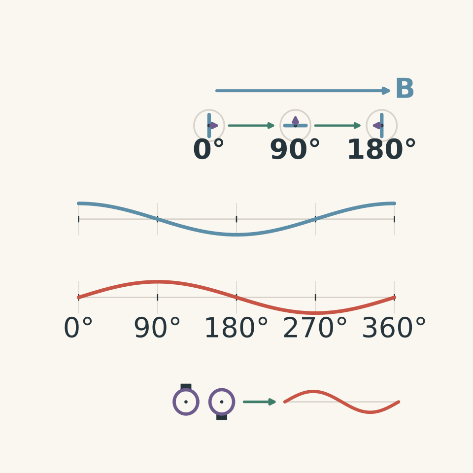
As the coil rotates at constant angular speed, the angle between its normal and the magnetic field changes continuously. If the angular speed is \(\omega\), the magnetic flux through one turn varies as:
\[ \Phi=BA\cos(\omega t), \]
where \(B\) is field strength, \(A\) is coil area, and \(t\) is time.
The flux linkage for \(N\) turns is \(N\Phi\). Faraday’s law states that the induced emf is the negative rate of change of flux linkage:
\[ \mathcal{E}=-\frac{d(N\Phi)}{dt}. \]
For constant angular speed, this produces a sinusoidal emf:
\[ \mathcal{E}=\mathcal{E}_{\max}\sin(\omega t), \qquad \mathcal{E}_{\max}=NAB\omega. \]
The sign depends on the chosen reference direction. The important point is that the emf alternates as the coil rotates.
Slip rings maintain continuous electrical connections between the rotating coil and the external circuit. They allow the output polarity to alternate rather than reversing the coil connections every half-turn.
Marking:
- 1 mark for explaining the sinusoidal change in flux linkage.
- 1 mark for connecting Faraday’s law to the sinusoidal emf.
- 1 mark for the role of slip rings.
(b) DC generator
A rotating coil still produces an alternating induced emf internally. A split-ring commutator reverses the coil’s connections to the external circuit every half-turn, keeping the external polarity in the same direction.
The output is therefore pulsating DC rather than a perfectly steady voltage. Brushes maintain electrical contact with the rotating commutator.
Marking:
- 1 mark for explaining how the split-ring commutator keeps the external polarity unidirectional.
- 1 mark for identifying the pulsating DC output and the brushes’ role.
Solution 9
(a) Stator and rotor components
The stator is stationary and contains the windings that produce the magnetic field. The squirrel-cage rotor contains conducting bars joined by end rings, forming closed conducting paths in which induced currents can flow.
Marking:
- 1 mark for the stator’s role.
- 1 mark for the rotor bars and end rings.
(b) How an AC induction motor rotates
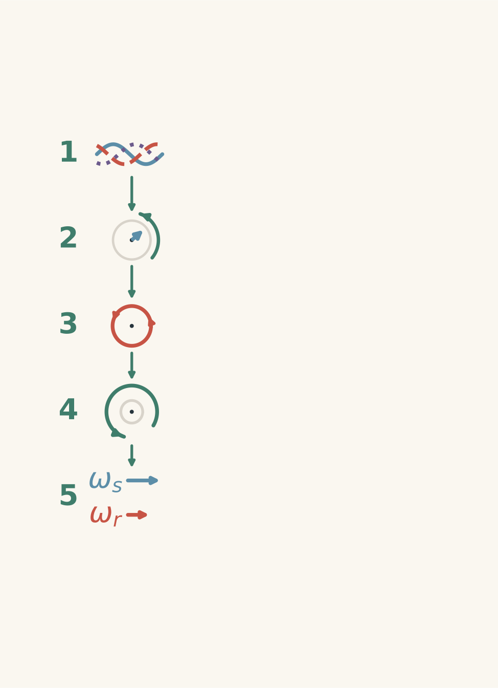
Three-phase alternating currents in the stator windings produce a rotating magnetic field.
The rotating field moves relative to the conductive rotor bars. The changing magnetic flux induces an emf and currents in the rotor. These rotor currents produce their own magnetic field, which interacts with the stator’s rotating field to produce electromagnetic torque.
The rotor must run below synchronous speed, the speed of the rotating magnetic field. If the rotor reached synchronous speed, there would be no relative motion between the rotor and the field. The changing flux responsible for inducing rotor currents would disappear, so the motor would lose its driving torque.
The difference between synchronous speed and rotor speed is associated with slip.
Marking:
- 1 mark for the rotating magnetic field.
- 1 mark for induced rotor currents.
- 1 mark for the interaction producing torque.
- 1 mark for explaining why the rotor runs below synchronous speed.
Solution 10
(a) Magnetic flux
Magnetic flux \(\Phi\) through a flat surface in a uniform magnetic field is:
\[ \Phi=BA\cos\theta, \]
where \(B\) is field strength, \(A\) is the area of one turn, and \(\theta\) is the angle between the magnetic field and the surface normal.
Substituting the values:
\[ \begin{aligned} \Phi&=(0.40)(1.5\times10^{-3})\cos60^\circ\\ &=3.0\times10^{-4}\ \mathrm{Wb}. \end{aligned} \]
Flux can change if the magnetic field strength changes, the area changes, or the angle between the field and the coil’s normal changes.
Marking:
- 1 mark for the flux relationship.
- 1 mark for the calculated flux per turn.
- 1 mark for identifying a valid way to change flux.
(b) Average induced emf
Faraday’s law gives the magnitude of the average induced emf:
\[ |\mathcal{E}_{\mathrm{avg}}| =N\frac{|\Delta\Phi|}{\Delta t}, \]
where \(N\) is the number of turns, \(\Delta\Phi\) is the change in flux per turn, and \(\Delta t\) is the time interval.
The change in flux magnitude is:
\[ |\Delta\Phi| =|0.5\times10^{-4}-3.0\times10^{-4}| =2.5\times10^{-4}\ \mathrm{Wb}. \]
Therefore:
\[ \begin{aligned} |\mathcal{E}_{\mathrm{avg}}| &=\frac{150(2.5\times10^{-4})}{0.025}\\ &=1.5\ \mathrm{V}. \end{aligned} \]
Marking:
- 1 mark for the correct Faraday’s law relationship and flux change.
- 1 mark for the average emf magnitude.
(c) Lenz’s law and induction from relative motion
The approaching magnet has a north pole facing the coil. By Lenz’s law, the induced current produces a magnetic effect that opposes the increase in flux caused by the approaching magnet.
The near face of the coil must therefore act as a north pole, repelling the approaching north pole. Using the right-hand grip rule, the induced current is anticlockwise when viewed from the magnet’s side.
More generally, an induced emf occurs when the magnetic flux linkage through a circuit changes. A moving conductor can also experience an induced emf as it moves through a magnetic field and magnetic forces separate its charges.
Marking:
- 1 mark for the correct Lenz’s law prediction and current direction.
- 1 mark for stating the condition for induction in moving-magnet or moving-conductor setups.
Solution 11
(a) Mutual induction
When the current in the primary solenoid changes, the magnetic field it produces also changes. This changes the magnetic flux linking the secondary solenoid, inducing an emf in that secondary circuit through mutual induction.
The solenoids do not need to be electrically connected. They are coupled magnetically through their shared flux.
Marking:
- 1 mark for linking changing primary current to changing magnetic field and flux.
- 1 mark for explaining that the changing shared flux induces an emf in the separate secondary circuit.
(b) Lenz’s law
As the primary current increases, the shared magnetic flux increases. The induced secondary current produces a magnetic effect that opposes this increase in flux.
Marking:
- 1 mark for correctly applying Lenz’s law to the increase in flux.
(c) Increasing the induced emf
One valid method is to increase the rate at which the primary current changes. This produces a faster change in magnetic flux linkage and a larger induced emf.
Other valid methods include increasing the number of secondary turns or improving magnetic coupling.
Marking:
- 1 mark for one valid method.
Solution 12
(a) Step-up and step-down transformers
For an ideal transformer, the voltage ratio equals the turns ratio:
\[ \frac{V_p}{V_s}=\frac{N_p}{N_s}, \]
where \(V_p\) and \(V_s\) are the primary and secondary voltages, and \(N_p\) and \(N_s\) are the corresponding numbers of turns.
Rearranging:
\[ V_s=V_p\frac{N_s}{N_p}. \]
For Transformer A:
\[ \begin{aligned} V_{s,A}&=240\frac{135}{900}\\ &=36\ \mathrm{V}. \end{aligned} \]
It is a step-down transformer because the secondary voltage is lower than the primary voltage.
For Transformer B:
\[ \begin{aligned} V_{s,B}&=240\frac{1800}{900}\\ &=480\ \mathrm{V}. \end{aligned} \]
It is a step-up transformer because the secondary voltage is higher than the primary voltage.
Marking:
- 1 mark for the correct step-down voltage.
- 1 mark for the correct step-up voltage.
- 1 mark for correctly classifying both transformers.
(b) Input power and secondary current
For Transformer A, the input power is:
\[ \begin{aligned} P_{\mathrm{in}}&=V_pI_p\\ &=(240)(0.40)\\ &=96\ \mathrm{W}. \end{aligned} \]
For an ideal transformer, input power equals output power:
\[ P_{\mathrm{out}}=P_{\mathrm{in}}=96\ \mathrm{W}. \]
Using \(P_{\mathrm{out}}=V_sI_s\), the secondary current is:
\[ \begin{aligned} I_s&=\frac{P_{\mathrm{out}}}{V_s}\\ &=\frac{96}{36}\\ &=2.67\ \mathrm{A}. \end{aligned} \]
Marking:
- 1 mark for the input power.
- 1 mark for applying ideal power conservation.
- 1 mark for the secondary current.
(c) Energy conservation
An ideal transformer transfers energy without losses, so:
\[ V_pI_p=V_sI_s. \]
A step-down transformer has a lower secondary voltage, so its secondary current must be higher to maintain the same power.
Marking:
- 1 mark for connecting conserved power to the inverse relationship between voltage and current.
Solution 13
(a) Resistive heating losses
Current flowing through a winding’s resistance produces heating. The power dissipated is:
\[ P_{\mathrm{loss}}=I^2R, \]
where \(I\) is current and \(R\) is winding resistance.
\[ \begin{aligned} P_{\mathrm{loss}}&=(2.0)^2(0.80)\\ &=3.2\ \mathrm{W}. \end{aligned} \]
A practical improvement is to use thicker, low-resistance copper wire for the winding. Reducing the winding resistance reduces the heating loss for a given current.
Marking:
- 1 mark for the calculated heating loss.
- 1 mark for a valid method of reducing winding losses.
(b) Eddy-current losses
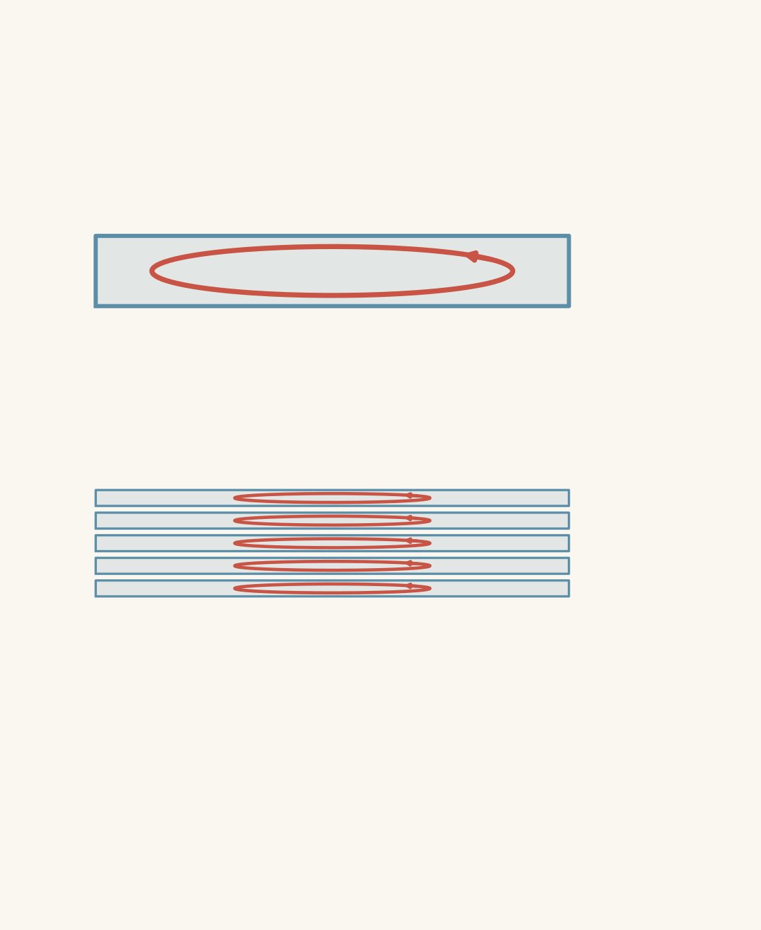
Changing magnetic flux in a conducting transformer core induces circulating currents called eddy currents. These currents dissipate energy as heat because the core has electrical resistance.
A laminated core consists of thin conductive sheets separated by electrical insulation. The insulation interrupts large circulating current paths and increases their resistance, reducing eddy currents and the resulting heating losses.
Marking:
- 1 mark for explaining how changing flux induces eddy currents and causes heating.
- 1 mark for explaining how insulation between laminations reduces circulating currents.
(c) Leakage flux and magnetic coupling
Leakage flux is magnetic flux produced by the primary winding that does not link the secondary winding. It reduces the proportion of magnetic flux shared by both windings.
Magnetic coupling can be improved by winding the primary and secondary close together on a common, closed soft-iron core with small air gaps. This helps more of the primary flux link the secondary.
Marking:
- 1 mark for defining leakage flux correctly.
- 1 mark for a valid method of improving magnetic coupling.
Solution 14
(a) Eddy-current braking
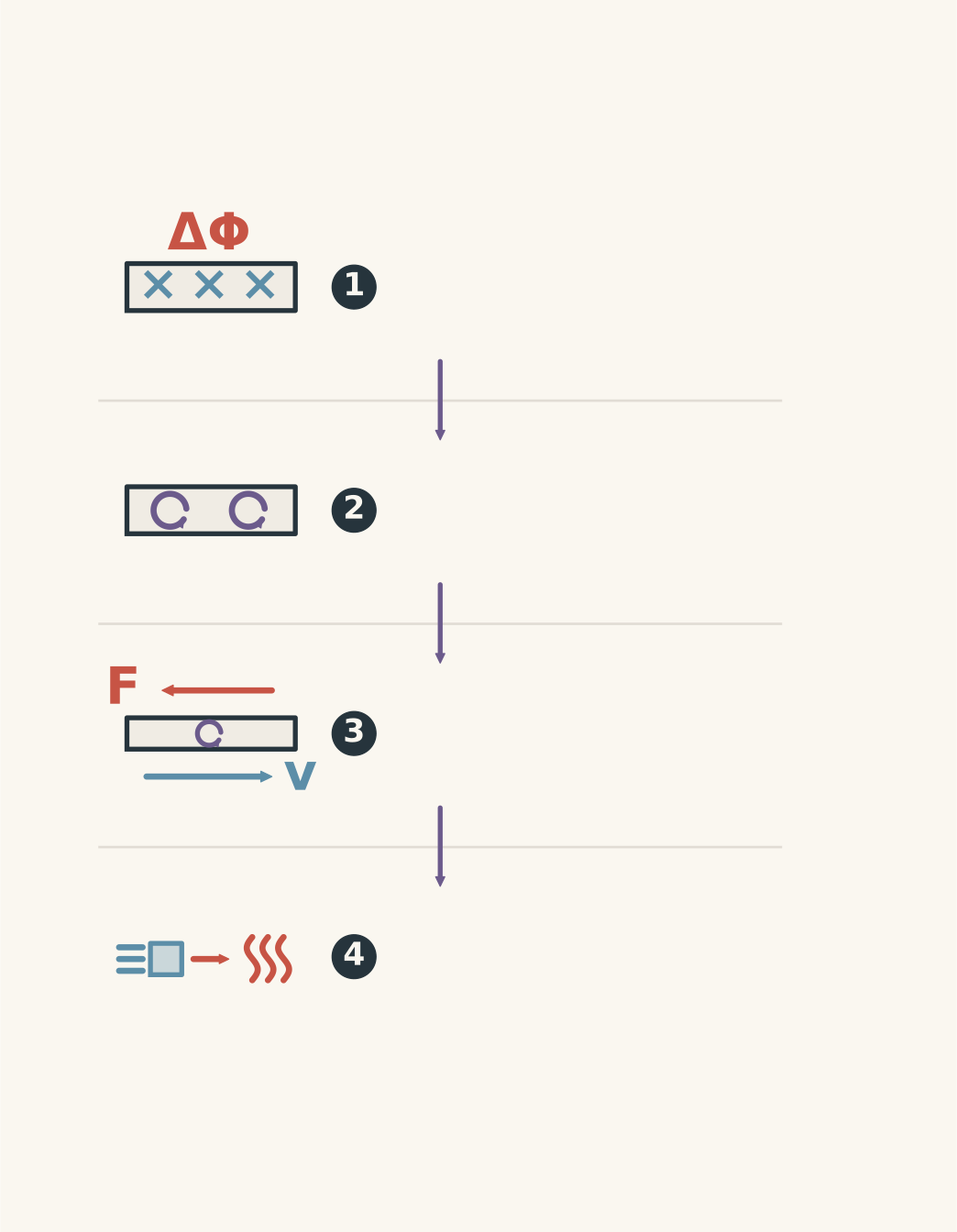
As the conducting plate moves through the magnetic-field region, the magnetic flux through loops within the plate changes. This induces eddy currents in the plate.
By Lenz’s law, the magnetic effects of these currents oppose the change that produces them. The resulting force opposes the plate’s motion, producing magnetic braking.
Marking:
- 1 mark for explaining how changing flux induces eddy currents.
- 1 mark for explaining how Lenz’s law produces an opposing braking force.
(b) Energy conservation
The plate’s kinetic energy is converted mainly into thermal energy as the induced currents encounter electrical resistance. The energy is not destroyed; it is transferred into the internal energy of the plate and surrounding materials.
Marking:
- 1 mark for identifying the conversion of kinetic energy into thermal energy.
Solution 15
(a) Input power
Input power is the primary voltage multiplied by the primary current:
\[ \begin{aligned} P_{\mathrm{in}}&=V_pI_p\\ &=(240)(0.50)\\ &=120\ \mathrm{W}. \end{aligned} \]
Marking:
- 1 mark for the correct input power.
(b) Output power
Output power is the secondary voltage multiplied by the secondary current:
\[ \begin{aligned} P_{\mathrm{out}}&=V_sI_s\\ &=(24)(4.0)\\ &=96\ \mathrm{W}. \end{aligned} \]
Marking:
- 1 mark for the correct output power.
(c) Efficiency
Efficiency is the useful output power divided by the input power, expressed as a percentage:
\[ \begin{aligned} \eta&=\frac{P_{\mathrm{out}}}{P_{\mathrm{in}}}\times100\%\\ &=\frac{96}{120}\times100\%\\ &=80\%. \end{aligned} \]
The remaining \(24\ \mathrm{W}\) represents power lost through non-ideal effects, such as winding resistance, eddy currents, and leakage flux.
Marking:
- 1 mark for the correct efficiency.