
Why Induced EMF Depends on Changing Magnetic Flux
Learn why a large, constant magnetic flux can produce zero induced emf, while a smaller flux changing rapidly produces a larger emf. Includes worked examples, Lenz’s law, and HSC-style practice questions with complete solutions.
You calculate a large magnetic flux through a coil and conclude that the induced emf must be large. Or you divide the flux by the time and write down \(\varepsilon=\Phi/t\). Both approaches make the same mistake: they treat magnetic flux as if it were induced emf. A coil can have a large, steady magnetic flux and zero induced emf, while a much smaller flux changing rapidly can produce a substantial emf.
Before reading on, predict which coil produces the larger average induced emf.
- Coil A has 100 turns and a magnetic flux of \(5.0\,\mathrm{mWb}\) per turn that stays constant for \(1.0\,\mathrm{s}\).
- Coil B has 10 turns, and its flux per turn increases from \(0.10\,\mathrm{mWb}\) to \(0.60\,\mathrm{mWb}\) in \(0.010\,\mathrm{s}\).
Coil B produces the larger emf: \(0.50\,\mathrm{V}\), compared with \(0\,\mathrm{V}\) for coil A. Coil A has much more flux, but none of it changes. Coil B has less flux, but that flux changes quickly.
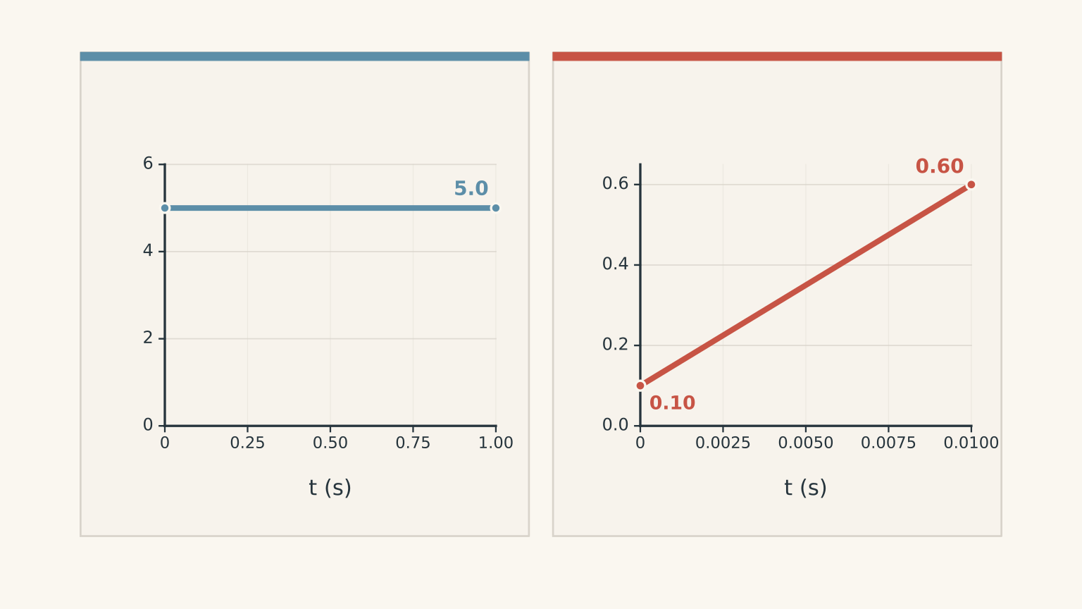
The principle behind this result is Faraday’s law of electromagnetic induction. Once you understand what the law measures, questions about changing magnetic fields, rotating coils, and induced current become much easier to solve.
01The mistake: confusing magnetic flux with induced emf
Magnetic flux, represented by \(\Phi\), describes how much magnetic field passes through a chosen surface. For a flat loop in a uniform magnetic field, calculate it using
\[ \Phi=BA\cos\theta \]
where:
- \(\Phi\) is magnetic flux, measured in webers (\(\mathrm{Wb}\)).
- \(B\) is magnetic flux density, measured in teslas (\(\mathrm{T}\)).
- \(A\) is the area enclosed by the loop, measured in square metres (\(\mathrm{m^2}\)).
- \(\theta\) is the angle between the magnetic field and the normal to the loop’s surface.
The normal is an imaginary line perpendicular to the surface. This angle is a common source of lost marks: \(\theta\) is measured from the normal, not from the plane of the loop.
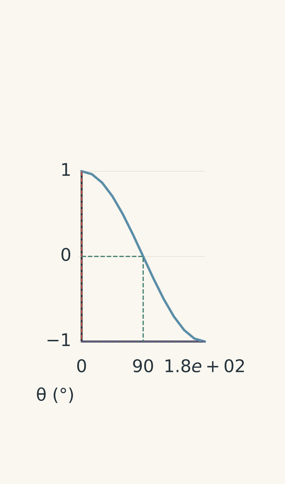
- Normalised magnetic flux
- Maximum positive flux (+1)
- Zero flux
- Maximum negative flux (−1)
When the magnetic field is perpendicular to the plane of the loop, it points along the normal, so \(\theta=0^\circ\) and the flux has its maximum positive value, \(BA\).
When the field is parallel to the plane of the loop, \(\theta=90^\circ\), so \(\cos90^\circ=0\). The flux is zero.
The equation describes the amount of flux at a particular instant. It does not, by itself, tell you the induced emf.
Three ways magnetic flux can change
Look again at \(\Phi=BA\cos\theta\). The flux can change if any of three things changes:
- Magnetic field strength: changing \(B\) changes the flux through the loop.
- Loop area: changing \(A\) changes the amount of field passing through the loop.
- Orientation: rotating the loop changes \(\theta\), and therefore changes the flux.
Three ways to change magnetic flux | Φ = BA cos θ
| 01 Magnetic field strength B | Change B only: B → 2B Keep loop area A and angle θ fixed. Result: Φ → 2Φ Flux increases in direct proportion to B. |
|---|---|
| 02 Loop area A | Change A only: A → 2A Keep field strength B and angle θ fixed. Result: Φ → 2Φ Flux increases in direct proportion to A. |
| 03 Orientation θ | Change θ only: 0° → 60° Keep field strength B and area A fixed. Result: Φ changes from BA to 0.5BA. Flux follows the cosine of the angle. |
The important point is that these are different ways of changing the same quantity: magnetic flux.
You could increase the magnetic field while rotating the loop so that its orientation reduces the flux. If the effects exactly cancel and the flux remains constant, there is no induced emf, even though the magnetic field itself has changed.
That is why checking only whether the field changes is not enough. You need to determine whether the flux through the loop changes.
02What Faraday’s law actually measures
An induced emf is a voltage generated by a changing magnetic flux through a circuit. Faraday’s law tells us that its magnitude depends on the rate of change of magnetic flux linkage.
For a coil with \(N\) turns, assuming each turn links the same magnetic flux, the average induced emf is
\[ \boxed{ |\varepsilon_{\mathrm{avg}}| =N\frac{|\Delta\Phi|}{\Delta t} } \]
Here:
- \(|\varepsilon_{\mathrm{avg}}|\) is the magnitude of the average induced emf, in volts.
- \(N\) is the number of turns in the coil.
- \(\Delta\Phi=\Phi_f-\Phi_i\) is the change in flux through one turn, in webers.
- \(\Delta t\) is the elapsed time, in seconds.
The signed form is
\[ \varepsilon_{\mathrm{avg}} =-N\frac{\Delta\Phi}{\Delta t} \]
The minus sign represents Lenz’s law, which determines the direction of the induced emf. Use the magnitude form when a question asks only for the size of the emf.
Notice what appears in the formula: the change in flux divided by the time taken. The starting flux does not appear by itself.
Why a smaller flux can produce a larger emf
Return to coils A and B from the opening example.
| Quantity | Coil A | Coil B |
|---|---|---|
| Number of turns, \(N\) | 100 | 10 |
| Initial flux per turn | \(5.0\,\mathrm{mWb}\) | \(0.10\,\mathrm{mWb}\) |
| Final flux per turn | \(5.0\,\mathrm{mWb}\) | \(0.60\,\mathrm{mWb}\) |
| Time taken | \(1.0\,\mathrm{s}\) | \(0.010\,\mathrm{s}\) |
| Average induced emf | \(0\,\mathrm{V}\) | \(0.50\,\mathrm{V}\) |
For coil A,
\[ \Delta\Phi=5.0-5.0=0\,\mathrm{mWb} \]
Therefore, its induced emf is zero.
For coil B,
\[ \begin{aligned} \Delta\Phi &=(0.60-0.10)\,\mathrm{mWb}\\ &=5.0\times10^{-4}\,\mathrm{Wb} \end{aligned} \]
So,
\[ \begin{aligned} |\varepsilon_{\mathrm{avg}}| &=10\frac{5.0\times10^{-4}\,\mathrm{Wb}} {0.010\,\mathrm{s}}\\ &=0.50\,\mathrm{V} \end{aligned} \]
Coil B has fewer turns and a much smaller flux than coil A, yet it produces a larger emf because its flux changes much more rapidly.
There are two separate ways to increase the induced emf for a given time interval: increase the change in flux per turn, or increase the number of turns.
03A reliable method for exam questions
When a question gives magnetic field strength, loop area, angle, number of turns, or a change over time, use this sequence rather than trying to guess which quantity matters most.

Step 1: Identify the flux information.
If the question gives magnetic flux directly, check whether it refers to one turn or the entire flux linkage. If it gives \(B\), \(A\), and \(\theta\), calculate the flux using \(\Phi=BA\cos\theta\).
Step 2: Calculate the initial and final flux.
Use the conditions at each stated time. If the magnetic field changes, use the corresponding value of \(B\). If the loop rotates, use the corresponding value of \(\theta\).
Step 3: Calculate the change in flux.
Subtract the initial value from the final value:
\[ \Delta\Phi=\Phi_f-\Phi_i \]
Keep the sign if the direction of the induced current matters.
Step 4: Calculate the average induced emf.
Use
\[ |\varepsilon_{\mathrm{avg}}| =N\frac{|\Phi_f-\Phi_i|}{\Delta t} \]
Convert milliw webers to webers before substituting. Remember that \(1\,\mathrm{mWb}=10^{-3}\,\mathrm{Wb}\).
Step 5: Determine the direction if required.
Use Lenz’s law to establish whether the induced magnetic field opposes an increase or a decrease in the external magnetic flux. Then use the right-hand grip rule to determine the conventional current direction.
This method separates three jobs that students often muddle together: finding the flux, calculating the emf magnitude, and determining its direction.
04Worked example: a changing magnetic field
A single-turn loop has an area of \(0.020\,\mathrm{m^2}\). Its area normal is parallel to a uniform magnetic field, which decreases from \(0.40\,\mathrm{T}\) to \(0.10\,\mathrm{T}\) in \(0.20\,\mathrm{s}\). Calculate the magnitude of the average induced emf.
A student calculates the initial flux and divides it by the time taken. Explain why that approach is incorrect.
Step 1
The area normal is parallel to the field, so \(\theta=0^\circ\).
\[ \begin{aligned} \Phi_i &=BA\cos0^\circ\\ &=(0.40\,\mathrm{T})(0.020\,\mathrm{m^2})\\ &=8.0\times10^{-3}\,\mathrm{Wb} \end{aligned} \]
Step 2
The area and orientation remain constant, but the magnetic field decreases to \(0.10\,\mathrm{T}\).
\[ \begin{aligned} \Phi_f &=BA\cos0^\circ\\ &=(0.10\,\mathrm{T})(0.020\,\mathrm{m^2})\\ &=2.0\times10^{-3}\,\mathrm{Wb} \end{aligned} \]
Step 3
\[ \begin{aligned} \Delta\Phi &=\Phi_f-\Phi_i\\ &=(2.0-8.0)\times10^{-3}\,\mathrm{Wb}\\ &=-6.0\times10^{-3}\,\mathrm{Wb} \end{aligned} \]
The negative sign means the flux has decreased relative to the chosen positive direction. For the emf magnitude, use the absolute value.
Step 4
There is one turn, and the time interval is \(0.20\,\mathrm{s}\).
\[ \begin{aligned} |\varepsilon_{\mathrm{avg}}| &=N\frac{|\Delta\Phi|}{\Delta t}\\ &=1\frac{6.0\times10^{-3}\,\mathrm{Wb}} {0.20\,\mathrm{s}}\\ &=0.030\,\mathrm{V} \end{aligned} \]
The average induced emf is \(0.030\,\mathrm{V}\).
Why the tempting method fails: dividing the initial flux by the time gives
\[ \frac{8.0\times10^{-3}\,\mathrm{Wb}} {0.20\,\mathrm{s}} =0.040\,\mathrm{V} \]
That is incorrect because the initial flux is not the change in flux. The loop still has \(2.0\times10^{-3}\,\mathrm{Wb}\) of flux per turn at the end, so only the difference between the two values contributes to the average emf.
05Worked example: changing the orientation of a coil
A 40-turn coil has an area of \(3.0\times10^{-3}\,\mathrm{m^2}\). It is in a uniform \(0.25\,\mathrm{T}\) magnetic field. The angle between the field and the area normal changes from \(0^\circ\) to \(60^\circ\) in \(0.015\,\mathrm{s}\). The magnetic field strength and coil area remain constant. Calculate the magnitude of the average induced emf.
Step 1
Initially, the area normal is parallel to the magnetic field.
\[ \begin{aligned} \Phi_i &=BA\cos0^\circ\\ &=(0.25)(3.0\times10^{-3})(1)\\ &=7.5\times10^{-4}\,\mathrm{Wb} \end{aligned} \]
Step 2
At the end, \(\theta=60^\circ\), so \(\cos60^\circ=0.50\).
\[ \begin{aligned} \Phi_f &=BA\cos60^\circ\\ &=(0.25)(3.0\times10^{-3})(0.50)\\ &=3.75\times10^{-4}\,\mathrm{Wb} \end{aligned} \]
Step 3
\[ \begin{aligned} \Delta\Phi &=\Phi_f-\Phi_i\\ &=(3.75-7.50)\times10^{-4}\,\mathrm{Wb}\\ &=-3.75\times10^{-4}\,\mathrm{Wb} \end{aligned} \]
The flux has decreased because the loop’s orientation has changed, even though the magnetic field strength has stayed constant.
Step 4
\[ \begin{aligned} |\varepsilon_{\mathrm{avg}}| &=N\frac{|\Delta\Phi|}{\Delta t}\\ &=40\frac{3.75\times10^{-4}\,\mathrm{Wb}} {0.015\,\mathrm{s}}\\ &=1.0\,\mathrm{V} \end{aligned} \]
The average induced emf is \(1.0\,\mathrm{V}\).
Why the tempting method fails: using \(N\Phi_i/\Delta t\) would give \(2.0\,\mathrm{V}\), twice the correct answer. That calculation assumes the flux changes from its initial value all the way to zero. In fact, the final flux is half the initial flux, so only half of the initial flux is lost.
This example also shows why you must calculate the flux at both states. A question does not need to change the magnetic field to induce an emf. Rotating a coil can change its flux just as effectively.
06Lenz’s law: why the induced current opposes the change
Faraday’s law gives you the magnitude of the induced emf. Its signed form also contains the clue to the direction of the induced effect:
\[ \varepsilon_{\mathrm{avg}} =-N\frac{\Delta\Phi}{\Delta t} \]
The minus sign represents Lenz’s law: the induced current produces a magnetic field that opposes the change in magnetic flux that caused it.
Notice the wording. The induced field does not always oppose the external magnetic field. It opposes the change in that field’s flux through the loop.
Consider an external magnetic flux pointing into the page.
| Change in external flux | Induced magnetic field | Conventional current, viewed face-on |
|---|---|---|
| Into the page, increasing | Out of the page | Anticlockwise |
| Into the page, decreasing | Into the page | Clockwise |
Lenz’s law | Face-on view of the loop
| 01 Increasing flux into the page | External flux: ⊗ Into the page — increasing Induced magnetic field: ⊙ Out of the page Conventional current: ↺ Anticlockwise The induced field opposes the increase. |
|---|---|
| 02 Decreasing flux into the page | External flux: ⊗ Into the page — decreasing Induced magnetic field: ⊗ Into the page Conventional current: ↻ Clockwise The induced field opposes the decrease. |
In the first case, the external flux into the page is increasing. The induced field points out of the page to resist that increase.
In the second case, the external flux into the page is decreasing. The induced field points into the page to resist that decrease. Here, the induced field points in the same direction as the external field.
That second case is where the shortcut “the induced field always opposes the external field” fails. If the external flux is decreasing, the induced effect acts to sustain it.
How this connects to conservation of energy
Suppose you move a magnet towards a conducting loop, increasing the magnetic flux through it. The induced current produces a magnetic field that resists the approach.
You must do work to keep moving the magnet towards the loop. That work is transferred into electrical energy and, if the circuit has resistance, ultimately into thermal energy.
If the induced current instead reinforced the change in flux, it could make the change happen faster, producing a stronger induced current that reinforced the change even more. Energy would appear without an external source.
Lenz’s law prevents this. The induced effect resists the change, and the energy transferred into the circuit comes from the external agent or source changing the flux.
This is not an extra rule bolted onto Faraday’s law. It is the direction required for electromagnetic induction to remain consistent with conservation of energy.
07Shortcuts that break under exam conditions
Some statements sound reasonable until the question changes one detail. Use the corrected rule rather than memorising a single pattern.
| Tempting shortcut | Correct reasoning |
|---|---|
| A stronger magnetic field produces a larger induced emf. | Only if it produces a greater rate of change of flux linkage. A strong, constant field can give zero emf. |
| The angle is measured from the plane of the loop. | In \(\Phi=BA\cos\theta\), the angle is measured from the area normal. |
| Zero flux means zero emf. | Zero flux at one instant does not mean the flux is unchanging. The flux may be passing through zero rapidly. |
| Equal initial and final flux means no emf occurred. | The average signed emf over the full interval is zero, but the emf may have been nonzero during parts of the interval. |
| If the magnetic field changes, the flux must change. | Changes in field strength, area, and orientation can offset one another, leaving the flux constant. |
| Induced emf and current are the same thing. | Emf is the induced voltage. In a simple closed resistive circuit, the current also depends on the circuit resistance. |
The fourth row deserves particular attention.
Imagine that the signed magnetic flux increases steadily and then decreases steadily back to its starting value. The net change over the entire interval is zero, but the flux changes throughout both stages.
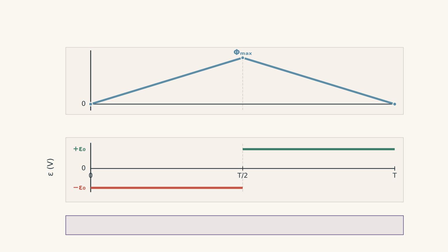
For the entire interval,
\[ \Delta\Phi_{\mathrm{total}}=0 \]
so the average signed emf over that interval is zero. But applying Faraday’s law separately to each segment gives a nonzero emf in each segment, with opposite signs.
Averaging the signed emf over the entire interval can hide what happened in between. This is why you must pay attention to the time interval specified in a question.
08A 10-second exam self-check
Before moving on from an induction calculation, run through these six points:
- Have I identified the magnetic flux per turn?
- Have I measured \(\theta\) from the area normal?
- Have I calculated the initial and final flux, rather than using just one value?
- Have I used \(\Delta\Phi=\Phi_f-\Phi_i\) and converted units correctly?
- Have I multiplied by the number of turns and divided by the elapsed time?
- If direction is required, have I used Lenz’s law to oppose the change in flux rather than automatically opposing the external field?
If you can answer all six, you have a dependable method for most HSC questions involving induced emf.
09Questions and solutions
Question 1
A 15-turn coil has a magnetic flux per turn that increases from \(0.40\,\mathrm{mWb}\) to \(1.0\,\mathrm{mWb}\) in \(0.030\,\mathrm{s}\).
Calculate the magnitude of the average induced emf.
Solution 1
The average induced emf has a magnitude of \(0.30\,\mathrm{V}\). Faraday’s law requires the change in flux per turn, multiplied by the number of turns, divided by the time taken.
First, calculate the change in flux:
\[ \begin{aligned} \Delta\Phi &=(1.0-0.40)\,\mathrm{mWb}\\ &=0.60\times10^{-3}\,\mathrm{Wb}\\ &=6.0\times10^{-4}\,\mathrm{Wb} \end{aligned} \]
Then apply Faraday’s law:
\[ \begin{aligned} |\varepsilon_{\mathrm{avg}}| &=N\frac{|\Delta\Phi|}{\Delta t}\\ &=15\frac{6.0\times10^{-4}\,\mathrm{Wb}} {0.030\,\mathrm{s}}\\ &=0.30\,\mathrm{V} \end{aligned} \]
The tempting error is to divide the final flux by the time. The correct calculation uses the difference between the final and initial flux, because the induced emf depends on the change rather than the absolute flux.
Question 2
A 30-turn loop has an area of \(4.0\times10^{-3}\,\mathrm{m^2}\) and is placed in a uniform \(0.50\,\mathrm{T}\) magnetic field.
The angle between the field and the loop’s area normal changes from \(30^\circ\) to \(90^\circ\) in \(0.020\,\mathrm{s}\). The field strength and loop area remain constant.
Calculate the magnitude of the average induced emf. Explain why the fact that the final flux is zero does not mean that the average emf over the interval is zero.
Solution 2
The magnitude of the average induced emf is approximately \(2.6\,\mathrm{V}\). The final flux is zero, but the initial flux is not, so there is a nonzero change in flux.
Calculate the initial flux per turn:
\[ \begin{aligned} \Phi_i &=BA\cos30^\circ\\ &=(0.50)(4.0\times10^{-3})(0.866)\\ &=1.73\times10^{-3}\,\mathrm{Wb} \end{aligned} \]
At the final angle,
\[ \begin{aligned} \Phi_f &=BA\cos90^\circ\\ &=0\,\mathrm{Wb} \end{aligned} \]
Therefore,
\[ \begin{aligned} \Delta\Phi &=\Phi_f-\Phi_i\\ &=-1.73\times10^{-3}\,\mathrm{Wb} \end{aligned} \]
Now calculate the average emf magnitude:
\[ \begin{aligned} |\varepsilon_{\mathrm{avg}}| &=N\frac{|\Delta\Phi|}{\Delta t}\\ &=30\frac{1.73\times10^{-3}\,\mathrm{Wb}} {0.020\,\mathrm{s}}\\ &=2.60\,\mathrm{V} \end{aligned} \]
The flux reaches zero at the end because the field lies in the plane of the loop. That does not erase the change that occurred during the interval. The average emf is determined by the initial and final flux values, not by the final value alone.
Question 3
Two coils experience different changes in signed magnetic flux. Positive flux is defined as flux in the direction of a chosen area normal.
- Coil A has 100 turns. Its flux per turn changes from \(+0.40\,\mathrm{mWb}\) to \(+0.80\,\mathrm{mWb}\) in \(0.20\,\mathrm{s}\).
- Coil B has 20 turns. Its flux per turn changes from \(+0.10\,\mathrm{mWb}\) to \(-0.50\,\mathrm{mWb}\) in \(0.010\,\mathrm{s}\).
Which coil has the greater average induced emf magnitude, and by what factor? Explain why the sign of coil B’s final flux matters.
Solution 3
Coil B produces an average induced emf six times that of coil A. Its flux changes more rapidly, and its flux reverses direction relative to the chosen normal.
For coil A,
\[ \begin{aligned} \Delta\Phi_A &=(0.80-0.40)\,\mathrm{mWb}\\ &=4.0\times10^{-4}\,\mathrm{Wb} \end{aligned} \]
Therefore,
\[ \begin{aligned} |\varepsilon_A| &=100\frac{4.0\times10^{-4}\,\mathrm{Wb}} {0.20\,\mathrm{s}}\\ &=0.20\,\mathrm{V} \end{aligned} \]
For coil B, the final flux is negative, so subtracting the initial value gives
\[ \begin{aligned} \Delta\Phi_B &=(-0.50-0.10)\,\mathrm{mWb}\\ &=-0.60\,\mathrm{mWb}\\ &=-6.0\times10^{-4}\,\mathrm{Wb} \end{aligned} \]
Hence,
\[ \begin{aligned} |\varepsilon_B| &=20\frac{6.0\times10^{-4}\,\mathrm{Wb}} {0.010\,\mathrm{s}}\\ &=1.2\,\mathrm{V} \end{aligned} \]
The ratio is
\[ \frac{|\varepsilon_B|}{|\varepsilon_A|} =\frac{1.2}{0.20}=6 \]
The final flux of coil B is negative because it points opposite to the chosen normal. Using the difference between the signed values gives a change of \(0.60\,\mathrm{mWb}\) in magnitude. Subtracting only the magnitudes of the two flux values would incorrectly give \(0.40\,\mathrm{mWb}\).
Question 4
Viewed face-on, the external magnetic flux through a conducting loop points into the page. During the first interval, this flux increases steadily. During the second interval, it decreases at the same rate.
For each interval:
- State the direction of the induced magnetic field.
- State the direction of the conventional induced current.
- Explain how the result illustrates Lenz’s law and conservation of energy.
Solution 4
During the first interval, the induced magnetic field points out of the page and the conventional current is anticlockwise. During the second interval, the induced field points into the page and the current is clockwise.
First interval: increasing flux into the page.
The induced field opposes the increase, so it points out of the page. By the right-hand grip rule, an anticlockwise conventional current produces this field.
Second interval: decreasing flux into the page.
The induced field opposes the decrease by supporting the flux into the page. A clockwise conventional current produces this field.
Because the magnitude of the flux change per unit time is the same in both intervals, the average induced emf magnitudes are equal, assuming the same number of turns. The direction reverses because the flux changes in opposite senses.
This illustrates why Lenz’s law opposes the change, not necessarily the external field. During the second interval, the induced field points in the same direction as the external field because it resists the reduction in flux.
The energy transferred to the circuit comes from whatever causes the external flux to change. For example, an agent moving a magnet towards or away from a loop must do work against the induced magnetic effect. That work is transferred into electrical energy and can be dissipated as heat. The induced current cannot create energy from nothing.
Question 5
A 10-turn coil is connected to a \(4.0\,\Omega\) resistor. Its signed magnetic flux per turn is initially \(+0.20\,\mathrm{mWb}\). The flux then increases linearly to \(+1.00\,\mathrm{mWb}\) in \(0.040\,\mathrm{s}\), before decreasing linearly back to \(+0.20\,\mathrm{mWb}\) over the next \(0.040\,\mathrm{s}\).
Take positive flux to be out of the page, and define positive current as anticlockwise when viewed from that side. Treat the given flux as externally imposed, neglect self-inductance, and assume the total circuit resistance is constant.
A student argues:
“The initial and final flux are equal, so the induced emf is zero throughout the \(0.080\,\mathrm{s}\) interval. No current flows, and no energy is transferred.”
Determine:
(a) The signed average induced emf during each \(0.040\,\mathrm{s}\) interval.
(b) The current magnitude and direction during each interval.
(c) The total energy dissipated in the resistor over the full \(0.080\,\mathrm{s}\).
(d) The average signed emf over the entire interval, and why it does not imply zero induction or zero energy transfer.
(e) The net signed charge transferred through the resistor over the entire interval.
Solution 5
The student is incorrect. The signed average emf is \(-0.20\,\mathrm{V}\) during the first interval and \(+0.20\,\mathrm{V}\) during the second. The current reverses direction, \(8.0\times10^{-4}\,\mathrm{J}\) of energy is dissipated as heat, and the net signed charge is zero.
The key is to apply Faraday’s law separately to the two intervals before considering the full \(0.080\,\mathrm{s}\).
(a) Signed average induced emf
During the first interval, the flux increases by
\[ \begin{aligned} \Delta\Phi_1 &=(1.00-0.20)\,\mathrm{mWb}\\ &=+8.0\times10^{-4}\,\mathrm{Wb} \end{aligned} \]
Faraday’s law gives
\[ \begin{aligned} \varepsilon_1 &=-N\frac{\Delta\Phi_1}{\Delta t}\\ &=-10\frac{8.0\times10^{-4}\,\mathrm{Wb}} {0.040\,\mathrm{s}}\\ &=-0.20\,\mathrm{V} \end{aligned} \]
During the second interval, the flux decreases by the same amount:
\[ \Delta\Phi_2=-8.0\times10^{-4}\,\mathrm{Wb} \]
Therefore,
\[ \begin{aligned} \varepsilon_2 &=-10\frac{-8.0\times10^{-4}\,\mathrm{Wb}} {0.040\,\mathrm{s}}\\ &=+0.20\,\mathrm{V} \end{aligned} \]
The emf is nonzero in both intervals, but its sign reverses because the direction of the flux change reverses.
(b) Current magnitude and direction
With negligible self-inductance, use Ohm’s law:
\[ I=\frac{\varepsilon}{R} \]
During the first interval,
\[ I_1=\frac{-0.20\,\mathrm{V}}{4.0\,\Omega} =-0.050\,\mathrm{A} \]
The negative sign means the current is clockwise.
During the second interval,
\[ I_2=\frac{+0.20\,\mathrm{V}}{4.0\,\Omega} =+0.050\,\mathrm{A} \]
The positive sign means the current is anticlockwise.
The current magnitude is \(0.050\,\mathrm{A}\) in both intervals. It reverses direction when the flux changes from increasing to decreasing.
(c) Total energy dissipated
The electrical power dissipated in the resistor is
\[ P=I^2R \]
Substituting the current magnitude,
\[ \begin{aligned} P &=(0.050\,\mathrm{A})^2(4.0\,\Omega)\\ &=0.010\,\mathrm{W} \end{aligned} \]
The power is positive in both intervals because it depends on the square of the current. Reversing the current does not reverse the direction of energy dissipation.
The total elapsed time is \(0.080\,\mathrm{s}\), so
\[ \begin{aligned} E&=P\Delta t\\ &=(0.010\,\mathrm{W})(0.080\,\mathrm{s})\\ &=8.0\times10^{-4}\,\mathrm{J} \end{aligned} \]
The resistor dissipates \(8.0\times10^{-4}\,\mathrm{J}\) of energy as heat.
(d) Average signed emf over the entire interval
The initial and final flux values are equal, so the total change in flux is zero:
\[ \begin{aligned} \Delta\Phi_{\mathrm{total}} &=\Phi_f-\Phi_i\\ &=(0.20-0.20)\,\mathrm{mWb}\\ &=0\,\mathrm{Wb} \end{aligned} \]
Consequently,
\[ \begin{aligned} \varepsilon_{\mathrm{avg,total}} &=-N\frac{\Delta\Phi_{\mathrm{total}}} {\Delta t}\\ &=0\,\mathrm{V} \end{aligned} \]
This is the average signed emf over the entire interval. It does not mean the emf was zero at every moment. The negative emf during the first interval and positive emf during the second cancel when averaged over the full interval.
The energy transfer does not cancel. Power dissipated in the resistor depends on \(I^2R\), which remains positive even when the current reverses. The energy ultimately comes from the external source or agent changing the magnetic flux.
(e) Net signed charge
The signed charge transferred during each interval is
\[ Q=I\Delta t \]
Using the current signs established in part (b),
\[ \begin{aligned} Q_{\mathrm{net}} &=I_1(0.040\,\mathrm{s}) +I_2(0.040\,\mathrm{s})\\ &=(-0.050)(0.040)+(0.050)(0.040)\\ &=0\,\mathrm{C} \end{aligned} \]
The net signed charge is zero because equal amounts of charge pass through the resistor in opposite directions during the two intervals.
This does not mean that no charge moved or that no energy was transferred. The circuit carried current in both intervals, and the resistor converted electrical energy into heat throughout.
The central lesson is that equal initial and final flux values tell you about the net change over the full interval, not the entire history of the flux. When a question combines induction with resistance and energy, analyse the changes in time first, then calculate current and power.
The next useful step is to keep induced emf, current, and power separate in your working. Faraday’s law determines the induced emf; the circuit resistance determines the current; and \(P=I^2R\) determines the rate at which electrical energy is dissipated. That separation becomes essential in HSC problems involving moving magnets, conducting loops, and energy transfer.