
How Transformers Work: From Magnetic Flux to Voltage
Learn why transformers need changing magnetic flux, how turns ratios determine secondary voltage, and how current, power, efficiency and core saturation affect transformer operation. Worked examples and practice questions demonstrate how to apply the key equations.
Australian mains electricity is about 230 V AC, but a small electrical circuit might need only 12 V. A transformer can reduce the voltage while transferring energy to a separate circuit, without electrically connecting the two windings.
But here’s the interesting part: if you replaced the AC supply with steady DC, would the secondary winding keep producing voltage just because the primary winding still has voltage? Make a prediction before reading on. The answer depends on what happens to the magnetic flux inside the transformer.
01Follow the magnetic flux
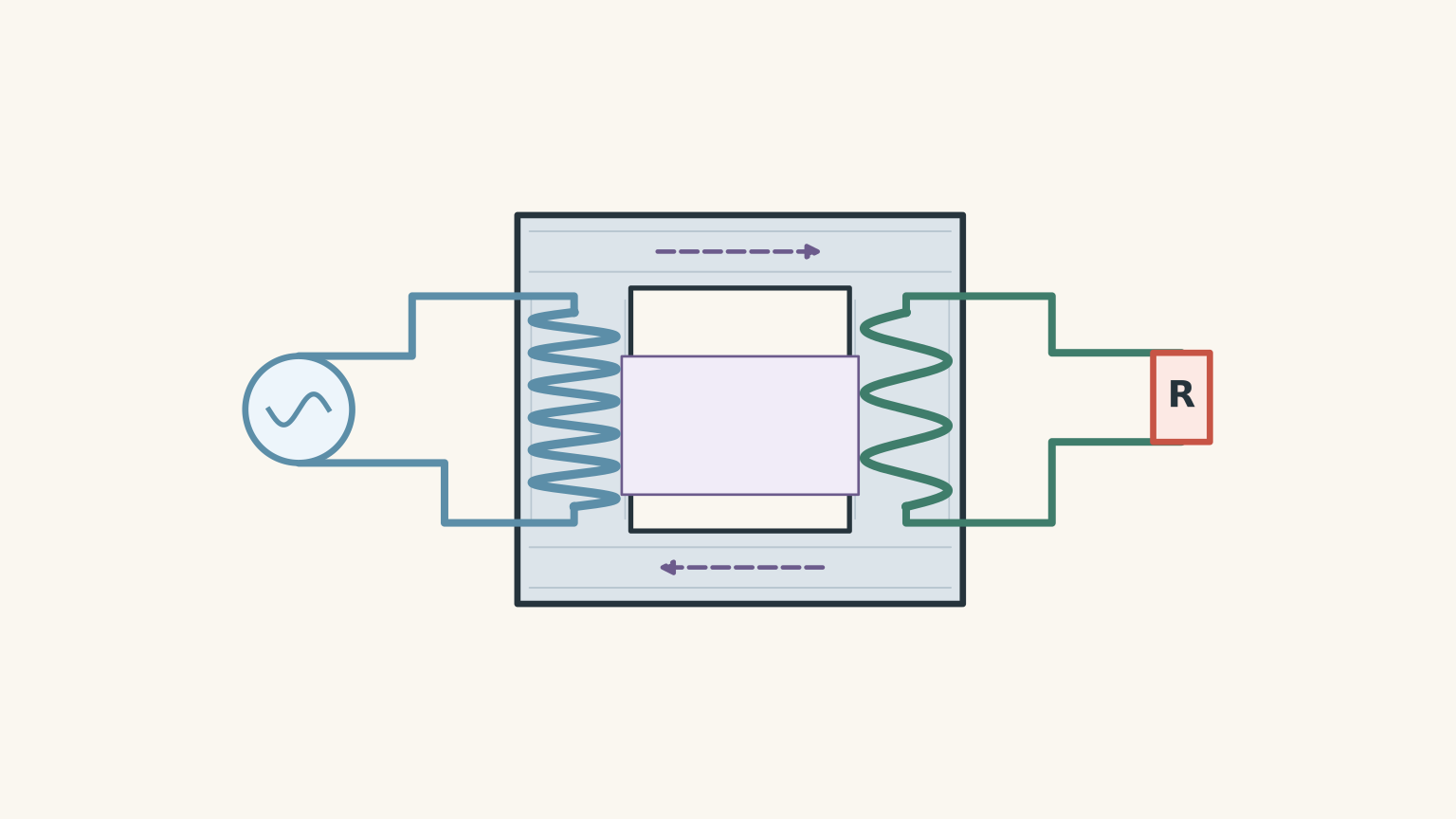
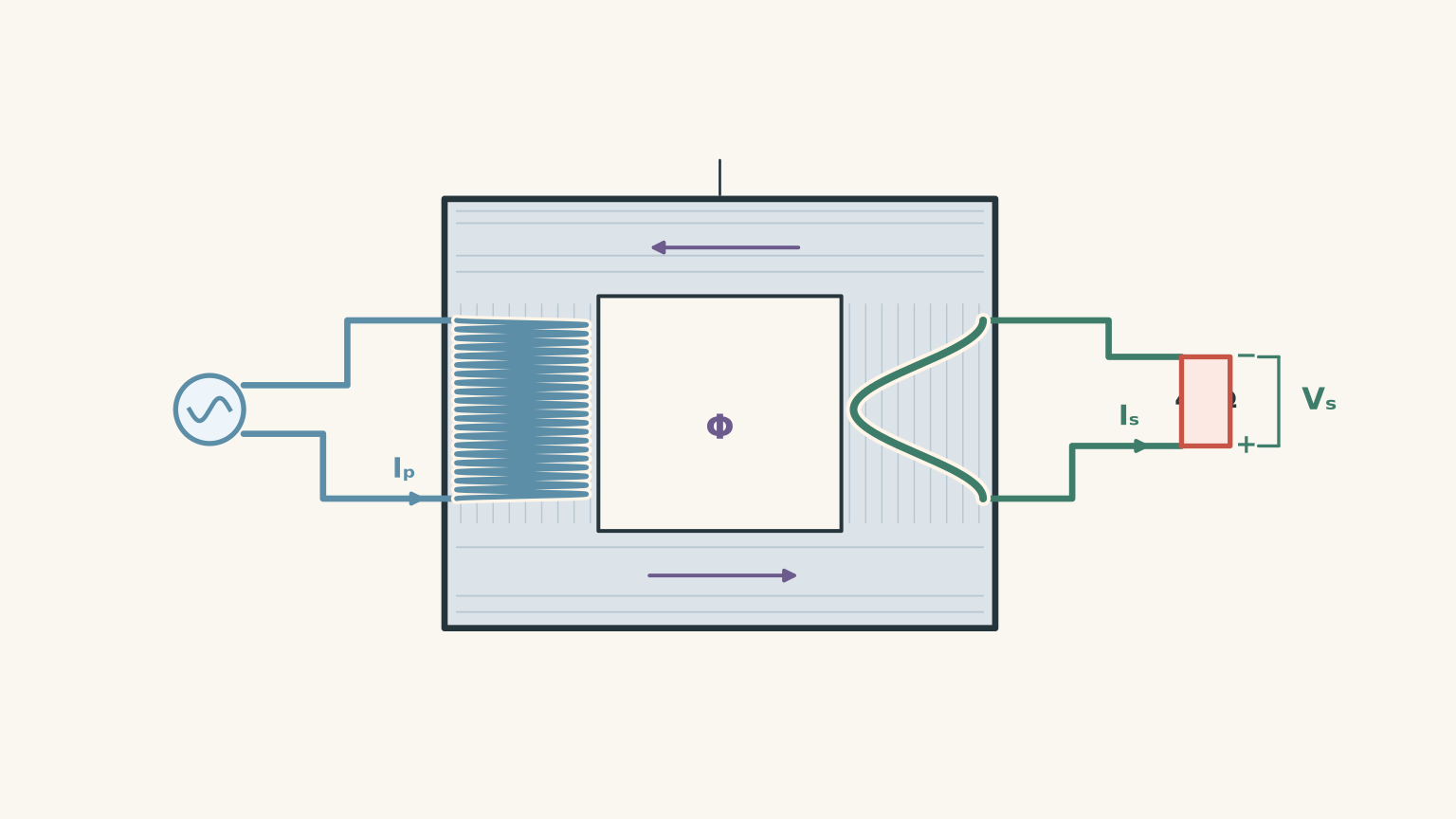
A transformer has two coils of wire, called windings, wrapped around a shared magnetic core.
- The primary winding connects to the electrical supply.
- The secondary winding connects to the circuit receiving energy.
- The core, usually made from laminated iron or electrical steel, provides a path for magnetic flux between the windings.
When alternating current flows through the primary winding, it produces a changing magnetic field. The core guides this field through the secondary winding.
The secondary winding responds to that changing magnetic field by developing a voltage of its own. This is called an induced voltage.
Notice what has happened: energy can be transferred between two circuits without electrons travelling from one winding into the other.
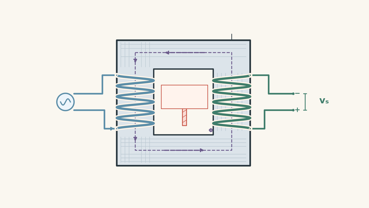
Here’s a useful way to picture it. Imagine two people on opposite sides of a shared trampoline. One keeps bouncing, and the other feels the movement without touching the first person. The changing magnetic field plays the role of the shared medium.
The analogy has a limit, though. No physical fabric moves inside a transformer. The coupling happens through a magnetic field, and the effect depends on how quickly the magnetic flux changes.
That last point is the key to understanding transformers.
02Faraday’s law: why changing flux creates voltage
Magnetic flux measures how much magnetic field passes through a loop of wire. We represent it by \(\Phi\), measured in webers (Wb).
Faraday’s law of electromagnetic induction tells us that a changing magnetic flux induces an electromotive force, or emf, in a coil.
\[ \mathcal{E}=-N\frac{d\Phi}{dt} \]
Here:
- \(\mathcal{E}\) is the induced emf, measured in volts.
- \(N\) is the number of turns in the coil.
- \(\Phi\) is the magnetic flux through one turn, measured in webers.
- \(\frac{d\Phi}{dt}\) is the rate at which the flux changes.
The minus sign represents Lenz’s law: the induced effect opposes the change that produces it.
For now, focus on the magnitude of the equation. Two things increase the induced emf:
- Increasing the number of turns.
- Changing the magnetic flux more rapidly.
If the flux stops changing, the induced emf becomes zero. A magnetic field can exist without inducing a voltage; it is the change in that field that matters.
So why does a transformer need AC?
Alternating current (AC) continually changes magnitude and direction. That makes the magnetic field and flux change, which induces a voltage in the secondary winding.
Direct current (DC), once it reaches a steady value, produces a steady magnetic field. The flux no longer changes, so there is no continuously induced secondary emf.
The difference is easiest to see by comparing the two situations.
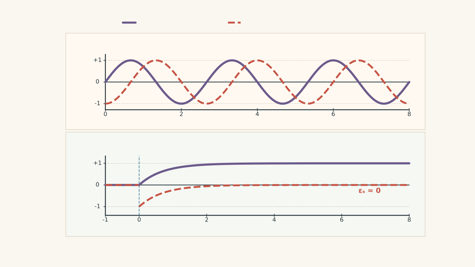
When DC is first switched on, the current does not jump instantaneously to its final value in a real inductive circuit. The flux changes during this brief transition, so a secondary voltage can be induced. When the current settles, the flux becomes constant and the secondary emf falls to zero. Switching the supply off can produce another brief pulse as the flux collapses.
So the precise rule is not that transformers magically recognise AC. They require changing magnetic flux to induce voltage continuously. AC is the usual way to provide that change.
There is also a practical problem with supplying DC to a conventional transformer. Once the initial transient has passed, the primary winding’s inductive opposition to changing current no longer limits the steady current in the usual AC manner. The current may become excessive, and the magnetic core may saturate. Either can cause overheating.
Electronics can convert DC into rapidly switched current, creating changing magnetic flux again. This is how transformers can operate inside modern high-frequency power supplies. A steady DC supply alone cannot do the job.
03The turns ratio determines the voltage
Now that we know where the induced voltage comes from, we can work out its size.
In a well-designed transformer, the changing flux links both windings. Applying Faraday’s law to each winding gives
\[ \mathcal{E}_p=-N_p\frac{d\Phi}{dt} \]
\[ \mathcal{E}_s=-N_s\frac{d\Phi}{dt} \]
The subscripts \(p\) and \(s\) refer to the primary and secondary windings.
Both windings experience approximately the same changing flux per turn. Dividing the magnitudes of the two equations therefore gives
\[ \frac{\mathcal{E}_s}{\mathcal{E}_p} =\frac{N_s}{N_p} \]
For an ideal transformer, the primary and secondary terminal voltages match the magnitudes of their respective induced emfs. This gives the transformer turns-ratio equation:
\[ \boxed{\frac{V_s}{V_p}=\frac{N_s}{N_p}} \]
Here, \(V_p\) and \(V_s\) are the primary and secondary voltages, and \(N_p\) and \(N_s\) are the numbers of turns in their respective windings.
For AC calculations, use the root-mean-square (rms) voltages unless the question specifies otherwise. The equation is exact for the ideal model and a useful approximation for a real transformer.
Step-up and step-down transformers
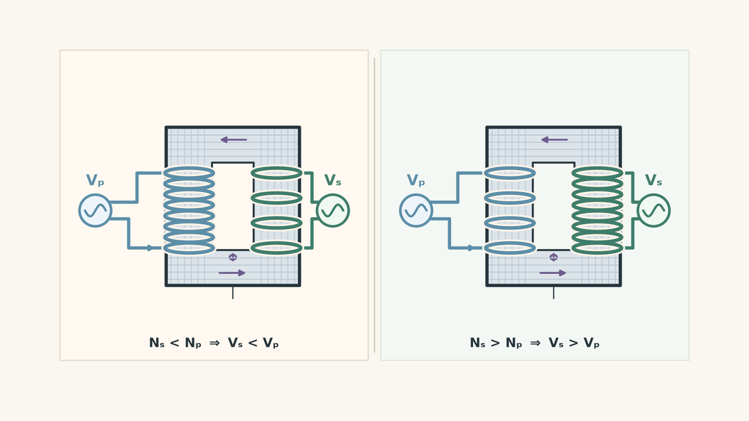
The turns ratio tells you whether a transformer increases or decreases voltage.
| Transformer type | Turns relationship | Effect on voltage |
|---|---|---|
| Step-up | \(N_s>N_p\) | \(V_s>V_p\) |
| Step-down | \(N_s\<N_p\) | \(V_s\<V_p\) |
| 1:1 transformer | \(N_s=N_p\) | \(V_s\approx V_p\) |
A step-up transformer is useful when a higher AC voltage is needed. A step-down transformer provides a lower AC voltage.
The voltage changes because each winding has a different number of turns experiencing the changing flux. More turns means a larger induced emf.
Worked example: find the secondary voltage
An ideal transformer has 1,000 turns in its primary winding and 50 turns in its secondary winding. The primary is connected to a 230 V rms AC supply. Calculate the secondary voltage.
Step 1: Identify the known values.
\[ \begin{aligned} V_p&=230\text{ V}\\\ N_p&=1000\\\ N_s&=50 \end{aligned} \]
Step 2: Rearrange the turns-ratio equation.
\[ V_s=V_p\frac{N_s}{N_p} \]
Step 3: Substitute the values.
\[ \begin{aligned} V_s&=230\times\frac{50}{1000}\\ &=11.5\text{ V} \end{aligned} \]
Answer: The secondary voltage is \(11.5\text{ V rms}\).
The secondary has one-twentieth as many turns as the primary, so its induced voltage is one-twentieth of the primary voltage. This is a step-down transformer.
04Voltage changes, but energy is not created
A transformer can increase voltage, but it cannot create energy. This is where current becomes important.
For an ideal transformer, the input power equals the output power. For a resistive load, we can write
\[ P_p=P_s \]
or
\[ V_p I_p=V_s I_s \]
where \(I_p\) and \(I_s\) are the rms primary and secondary currents, measured in amperes.
Combining this with the turns-ratio equation gives
\[ \boxed{\frac{I_s}{I_p}=\frac{N_p}{N_s}} \]
The current ratio is the inverse of the voltage ratio.
A step-down transformer produces a lower voltage but can deliver a larger current. A step-up transformer produces a higher voltage but delivers a smaller current for the same transferred power.
This is why you cannot argue that doubling the voltage automatically doubles the power. You must also know what happens to the current.
Worked example: calculate voltage, current, and power
An ideal transformer has 800 turns in its primary winding and 40 turns in its secondary winding. The primary is connected to a 230 V rms supply. A \(46\\,\Omega\) resistor is connected across the secondary.
Calculate:
- The secondary voltage.
- The secondary current.
- The primary current.
Step 1: Calculate the secondary voltage.
\[ \begin{aligned} V_s&=V_p\frac{N_s}{N_p}\\ &=230\times\frac{40}{800}\\ &=11.5\text{ V} \end{aligned} \]
Step 2: Calculate the secondary current using Ohm’s law.
For a resistor, \(V=IR\), so
\[ \begin{aligned} I_s&=\frac{V_s}{R}\\ &=\frac{11.5}{46}\\ &=0.25\text{ A} \end{aligned} \]
Step 3: Calculate the output power.
\[ \begin{aligned} P_s&=V_s I_s\\ &=11.5\times0.25\\ &=2.875\text{ W} \end{aligned} \]
Step 4: Use conservation of energy to find the primary current.
Because the transformer is ideal, \(P_p=P_s\). Therefore,
\[ \begin{aligned} I_p&=\frac{P_p}{V_p}\\ &=\frac{2.875}{230}\\ &=0.0125\text{ A} \end{aligned} \]
Converting to milliamperes gives
\[ I_p=12.5\text{ mA} \]
Answer: The secondary voltage is \(11.5\text{ V}\), the secondary current is \(0.25\text{ A}\), and the primary current is \(12.5\text{ mA}\).
Notice that the secondary current is 20 times the primary current, while the secondary voltage is 20 times lower. The power on both sides is \(2.875\text{ W}\), exactly as the ideal model requires.
05Why connecting a load changes the primary current
There’s one subtle part of transformer operation that the turns-ratio equation doesn’t explain by itself.
Imagine the transformer is connected to an AC supply, but nothing is connected to its secondary winding. The secondary can still have an induced voltage. However, with no closed secondary circuit, there is essentially no secondary current and no useful output power.
Now connect a resistor or lamp to the secondary.
Current flows through the load. That current produces its own magnetic effect, which opposes the change in flux responsible for inducing the current. This is Lenz’s law at work.
The primary then draws additional current from the supply to transfer energy to the load. The core flux remains approximately set by the primary voltage, frequency, and number of turns, rather than increasing dramatically just because the load has been connected.
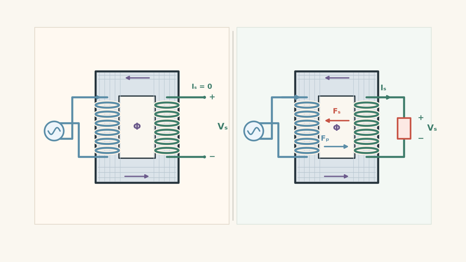
This resolves an important misconception: the two circuits do not need an electrical connection for energy to pass between them. The changing magnetic field couples the windings, while the primary supply provides the energy delivered to the load.
In a real transformer, the primary still draws a small magnetising current even when the secondary is open. When a load is connected, the primary current generally increases to supply the additional power.
06Where the ideal model stops being exact
Real transformers lose some energy as heat. The wire has electrical resistance, and changing magnetic fields produce eddy currents and repeated magnetisation changes in the core. Laminating the core into thin, insulated sheets helps reduce eddy-current losses.
The efficiency of a transformer is
\[ \eta=\frac{P_{\text{out}}}{P_{\text{in}}}\times100\% \]
Here, \(P_{\text{out}}\) is the useful output power and \(P_{\text{in}}\) is the input power. A real transformer has an efficiency below 100%, so its input power must exceed its output power.
There is another limit worth understanding: the turns ratio predicts the voltage relationship, but it does not tell you whether the transformer is operating safely.
For sinusoidal operation, Faraday’s law gives the proportional relationship
\[ V_p\propto fN_p\Phi_{\max} \]
where \(f\) is the AC frequency in hertz and \(\Phi_{\max}\) is the peak magnetic flux.
For a fixed number of primary turns, this means
\[ \Phi_{\max}\propto\frac{V_p}{f} \]
At a fixed primary voltage, reducing the frequency increases the peak flux. Halving the frequency doubles the flux required to induce the same primary voltage.
If the core is driven beyond its intended operating range, it can enter magnetic saturation. The core then becomes much less effective at supporting additional magnetic flux, and the magnetising current can rise sharply.
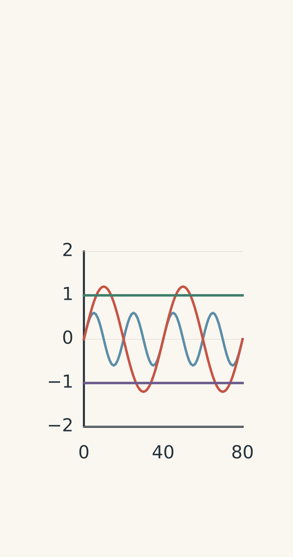
- 50 Hz — peak 0.60 Φsat
- 25 Hz predicted — peak 1.20 Φsat
- +Φsat — upper saturation limit
- −Φsat — lower saturation limit
This is why a transformer rated for a particular voltage and frequency cannot automatically be used at the same voltage and a much lower frequency. The turns ratio may still predict the ideal induced-voltage ratio, but that ratio does not guarantee safe operation or determine the actual current when saturation and other real-world effects become significant.
07Questions and solutions
Question 1
An ideal transformer has 800 turns in its primary winding and 120 turns in its secondary winding. It is connected to a 230 V rms AC supply.
Calculate the secondary rms voltage and state whether the transformer is step-up or step-down.
Solution 1
The secondary voltage is \(34.5\text{ V rms}\), and the transformer is step-down.
Use the turns-ratio equation:
\[ \begin{aligned} V_s&=V_p\frac{N_s}{N_p}\\ &=230\times\frac{120}{800}\\ &=34.5\text{ V} \end{aligned} \]
The secondary has fewer turns than the primary, so the secondary voltage is lower than the input voltage. This is a step-down transformer.
Question 2
A transformer supplies a resistive load at \(24\text{ V rms}\). The load draws \(3.0\text{ A}\), and the transformer has an efficiency of 90%.
The primary supply is \(230\text{ V rms}\). Assume the primary current is in phase with the supply voltage.
Calculate:
- The output power.
- The input power.
- The primary current.
Explain why the primary current is much smaller than the secondary current, even though the transformer loses some energy.
Solution 2
The output power is \(72\text{ W}\), the input power is \(80\text{ W}\), and the primary current is approximately \(0.348\text{ A}\).
First, calculate the output power:
\[ \begin{aligned} P_{\text{out}}&=V_s I_s\\ &=24\times3.0\\ &=72\text{ W} \end{aligned} \]
Efficiency is output power divided by input power. Rearranging gives
\[ \begin{aligned} P_{\text{in}}&=\frac{P_{\text{out}}}{\eta}\\ &=\frac{72}{0.90}\\ &=80\text{ W} \end{aligned} \]
The primary current follows from the input power:
\[ \begin{aligned} I_p&=\frac{P_{\text{in}}}{V_p}\\ &=\frac{80}{230}\\ &=0.348\text{ A} \end{aligned} \]
The primary current is much smaller because the primary voltage is much higher than the secondary voltage. For a given amount of power, higher voltage corresponds to lower current.
The transformer loses \(80-72=8\text{ W}\) as heat and other losses. These losses mean that the input power exceeds the output power, but they do not require the primary current to exceed the secondary current. Voltage and current must be considered together.
Question 3
A real transformer has 1,000 primary turns and 50 secondary turns. Its primary is connected to a \(230\text{ V rms}\) AC supply.
With the secondary open, a voltmeter reads \(11.5\text{ V}\). When a \(12\\,\Omega\) resistor is connected, the secondary terminal voltage falls to \(10.8\text{ V}\).
Calculate the load current and output power. Explain why the loaded voltage differs from the ideal turns-ratio prediction. Can you determine the exact primary current from the information given?
Solution 3
The load current is \(0.90\text{ A}\), the output power is \(9.72\text{ W}\), and the exact primary current cannot be determined from the given information.
Calculate the load current using Ohm’s law:
\[ \begin{aligned} I_s&=\frac{V_s}{R}\\ &=\frac{10.8}{12}\\ &=0.90\text{ A} \end{aligned} \]
Then calculate the output power:
\[ \begin{aligned} P_{\text{out}}&=V_s I_s\\ &=10.8\times0.90\\ &=9.72\text{ W} \end{aligned} \]
The ideal turns-ratio equation predicts
\[ V_s=230\times\frac{50}{1000} =11.5\text{ V} \]
This agrees with the open-circuit measurement. However, a real transformer has winding resistance and magnetic leakage. When the load draws current, these effects produce internal voltage drops, so the terminal voltage can fall below the ideal prediction.
The exact primary current cannot be calculated because the input power or transformer efficiency has not been supplied. Knowing the output power alone does not tell us how much additional power is lost inside the transformer.
The key distinction is that the ideal turns ratio describes the voltage relationship under ideal conditions. It does not guarantee that a real transformer’s loaded terminal voltage will remain exactly constant.
Question 4
In a thought experiment, a conventional transformer has its primary connected to a DC supply through a switch, with a high-resistance voltmeter across the secondary.
Describe what the voltmeter should show:
- Immediately after the switch closes.
- After the primary current has settled to a steady value.
- Briefly after the switch opens.
Explain why supplying DC can overheat the transformer, and whether rapidly switching the DC supply on and off can induce a secondary voltage.
Solution 4
The secondary shows a brief induced voltage while the flux changes, approximately zero voltage once the DC current settles, and another brief pulse when the supply is switched off.
Immediately after closing the switch, the primary current begins to change. The magnetic flux through the core changes as well, so Faraday’s law predicts a secondary emf.
After the current settles, the flux becomes approximately constant. Therefore,
\[ \frac{d\Phi}{dt}=0 \]
and the induced secondary emf becomes approximately zero.
When the switch opens, the magnetic flux collapses. This change can induce another brief voltage in the secondary.
A conventional transformer can overheat when supplied with DC because its steady current may be excessive, particularly if the core saturates. With no continuing change in current, the usual AC inductive opposition is absent from the steady-state current calculation, leaving the winding resistance and supply to limit the current.
Rapidly switching the DC can induce a secondary voltage because the magnetic flux repeatedly changes. However, a practical transformer circuit must be designed for the switching frequency, current, and core behaviour. It is not safe to assume that simply connecting a DC source to an ordinary transformer will work.
Question 5
An ideal-model transformer has 1,000 primary turns and 100 secondary turns. At \(230\text{ V rms}\) and \(50\text{ Hz}\), it supplies a \(23\\,\Omega\) resistor. Assume that, at this operating point, the peak magnetic flux is 60% of the core’s saturation flux.
Two students predict what happens when the supply changes to \(230\text{ V rms}\) at \(25\text{ Hz}\).
- Student A says the secondary voltage remains \(23\text{ V}\) because the turns ratio is unchanged, so the transformer should operate just as safely.
- Student B says the secondary voltage must fall to \(11.5\text{ V}\) because the frequency has halved.
Evaluate both predictions. Then calculate the secondary voltage, load current, output power, and ideal primary current if the supply is instead changed to \(115\text{ V rms}\) at \(25\text{ Hz}\).
Assume that the transformer operates below saturation in the final case, and ignore losses when calculating the ideal currents and powers.
Solution 5
Neither student has the whole story. The ideal turns ratio predicts \(23\text{ V}\) at \(25\text{ Hz}\), but the unchanged supply voltage drives the core into saturation, so safe operation cannot be assumed. Student B’s claim that the output voltage must halve is incorrect.
Start with the original operating point.
The ideal secondary voltage is
\[ \begin{aligned} V_s&=V_p\frac{N_s}{N_p}\\ &=230\times\frac{100}{1000}\\ &=23\text{ V} \end{aligned} \]
The load current is
\[ I_s=\frac{23}{23}=1.0\text{ A} \]
Therefore, the output power is
\[ P_{\text{out}}=23\times1.0=23\text{ W} \]
For an ideal transformer, the primary current is
\[ I_p=\frac{23}{230}=0.10\text{ A} \]
Now reduce the frequency from \(50\text{ Hz}\) to \(25\text{ Hz}\) while keeping the primary voltage at \(230\text{ V}\).
The turns ratio still predicts a secondary induced voltage of \(23\text{ V}\). Both windings link the same changing flux, so their induced-emf ratio is determined by their numbers of turns, not directly by the frequency.
However, the peak flux depends on the ratio of primary voltage to frequency:
\[ \Phi_{\max}\propto\frac{V_p}{f} \]
Halving the frequency while keeping the voltage constant doubles the predicted peak flux. The original peak flux was 60% of the saturation flux, so the new predicted peak is
\[ 2\times0.60=1.20 \]
or 120% of the saturation flux.
The core is therefore driven into saturation. Saturation does not impose a perfectly fixed maximum flux, but it causes the magnetising current to rise sharply. The transformer can draw excessive current and overheat.
This is the important distinction between the two students’ claims:
- Student A is correct that the ideal turns ratio predicts the same secondary induced voltage, but wrong to conclude that the transformer remains safe.
- Student B is wrong that halving frequency automatically halves the secondary voltage. The voltage ratio and the peak-flux requirement are separate relationships.
Once saturation and real transformer effects become significant, the exact primary current and loaded terminal voltage cannot be determined from the turns ratio alone.
Now consider the final case: \(115\text{ V rms}\) at \(25\text{ Hz}\).
The voltage and frequency have both been halved, so the ratio \(V_p/f\) remains unchanged. The peak flux therefore remains at 60% of the saturation flux, keeping the core within the stated operating limit.
Calculate the secondary voltage:
\[ \begin{aligned} V_s&=115\times\frac{100}{1000}\\ &=11.5\text{ V} \end{aligned} \]
Calculate the secondary current:
\[ \begin{aligned} I_s&=\frac{V_s}{R}\\ &=\frac{11.5}{23}\\ &=0.50\text{ A} \end{aligned} \]
Calculate the output power:
\[ \begin{aligned} P_{\text{out}}&=V_s I_s\\ &=11.5\times0.50\\ &=5.75\text{ W} \end{aligned} \]
Finally, calculate the ideal primary current:
\[ \begin{aligned} I_p&=\frac{P_{\text{out}}}{V_p}\\ &=\frac{5.75}{115}\\ &=0.050\text{ A} \end{aligned} \]
The final operating point is \(11.5\text{ V}\) secondary voltage, \(0.50\text{ A}\) secondary current, \(5.75\text{ W}\) output power, and \(0.050\text{ A}\) ideal primary current.
The deeper lesson is that the turns ratio alone does not describe every aspect of transformer behaviour. Faraday’s law explains the induced voltage, the turns ratio compares the two windings, and the voltage-to-frequency relationship determines how much magnetic flux the core must support.
These ideas lead naturally to the next topic: AC generators. A generator creates a changing magnetic flux through rotation, while a transformer uses changing magnetic flux to transfer energy and change voltage levels. Understanding both gives you a much clearer picture of how electrical energy is generated, transmitted, and supplied to the devices we use.