
Circuit Networks: Year 11-12 Physics Practice Exam
Test your understanding of series, parallel, and combination circuits with this original 50-mark tutorgum practice paper. Includes timed exam conditions, six questions, complete worked solutions, and a detailed marking guide.
This is an original tutorgum practice paper for Year 11-12 Physics revision, focused on circuit networks within the supplied Physics 2025 syllabus scope. It is not an official, endorsed, past, or predicted NESA paper. The assessment covers series, parallel, and reducible combination circuits, electrical resistance, current, potential difference, power, and Kirchhoff’s current and voltage laws.
01Exam instructions
Suggested working time: 60 minutes
Suggested reading time: 5 minutes
Total marks: 50
These are practice-paper conditions set by tutorgum, not official examination rules.
- Equipment: Scientific calculator and writing materials. Complete the paper without notes.
- Working: Show your calculations and reasoning. Numerical answers without working may not receive all available method marks.
- Units and precision: Include appropriate units and give answers to a sensible number of significant figures. Carry unrounded values through intermediate calculations.
- Circuit assumptions: All voltage sources are ideal, connecting wires have negligible resistance, and all resistors obey Ohm’s law. Ignore internal resistance and meter effects.
- Scope: This paper assesses series, parallel, and reducible combination circuits; equivalent resistance; current, potential difference, and electrical power; Kirchhoff’s current and voltage laws; conservation of charge and energy; and the effects of changing resistor values.
- Exclusions: Internal resistance, capacitors, alternating-current circuits, non-ohmic components, and other Physics topics are not assessed. The paper follows only the supplied Physics 2025 circuit-network scope and does not claim broader syllabus coverage.
02Questions
Question 1 (7 marks)
An ideal \(18.0\,\text{V}\) source is connected to a \(3.0\,\Omega\) resistor and a \(6.0\,\Omega\) resistor in series.
(a) Determine the equivalent resistance of the two resistors. (1 mark)
(b) Calculate the current supplied by the source. (2 marks)
(c) Determine the potential difference across the \(6.0\,\Omega\) resistor. (2 marks)
(d) Calculate the power dissipated by the \(3.0\,\Omega\) resistor. (2 marks)
Question 2 (8 marks)
An ideal \(12.0\,\text{V}\) source is connected across two resistors, \(6.0\,\Omega\) and \(3.0\,\Omega\), in parallel.
(a) State the potential difference across each resistor. (2 marks)
(b) Calculate the current through each resistor. (2 marks)
(c) Calculate the total current supplied by the source. (2 marks)
(d) Determine the equivalent resistance of the parallel combination. (2 marks)
Question 3 (9 marks)
An ideal \(20.0\,\text{V}\) source is connected to a \(4.0\,\Omega\) resistor in series with a parallel section containing a \(6.0\,\Omega\) resistor and a \(3.0\,\Omega\) resistor.
(a) Calculate the equivalent resistance of the parallel section. (2 marks)
(b) Determine the total equivalent resistance of the network. (1 mark)
(c) Calculate the total current supplied by the source. (2 marks)
(d) Determine the potential difference across the parallel section. (1 mark)
(e) Calculate the current through each resistor in the parallel section. (3 marks)
Question 4 (6 marks)
At a junction, currents of \(1.80\,\text{A}\) and \(0.65\,\text{A}\) enter the junction. Currents of \(0.90\,\text{A}\) and \(I\) leave it.
(a) Determine the unknown current, \(I\). (2 marks)
Consider a separate closed loop containing an ideal \(12.0\,\text{V}\) source and three resistors. The source provides a \(12.0\,\text{V}\) potential rise around the loop. The potential drops across the resistors are \(4.5\,\text{V}\), \(2.0\,\text{V}\), and \(V_x\).
(b) Calculate the unknown potential drop, \(V_x\). (2 marks)
(c) State the conservation principle underlying each of the following laws:
(i) Kirchhoff’s current law.
(ii) Kirchhoff’s voltage law. (2 marks)
Question 5 (10 marks)
An ideal \(24.0\,\text{V}\) source is connected to a \(4.0\,\Omega\) resistor and an \(8.0\,\Omega\) resistor in series.
(a) Calculate the total resistance and the current supplied by the source. (3 marks)
(b) Calculate the power dissipated by the \(8.0\,\Omega\) resistor. (2 marks)
(c) The \(8.0\,\Omega\) resistor is replaced with a \(4.0\,\Omega\) resistor. The source voltage remains \(24.0\,\text{V}\). Calculate the new current supplied by the source. (2 marks)
(d) Calculate the power dissipated by the replacement resistor. Compare it with the power calculated in part (b), and explain the change in terms of current and resistance. (3 marks)
Question 6 (10 marks)
An ideal \(15.0\,\text{V}\) source supplies a \(2.0\,\Omega\) resistor in series with a parallel section containing a \(6.0\,\Omega\) resistor and an unknown resistor, \(R\).
The current in the main line, before it splits into the two parallel branches, is \(3.0\,\text{A}\).
(a) Determine the total equivalent resistance of the network. (1 mark)
(b) Determine the equivalent resistance of the parallel section. (2 marks)
(c) Calculate the potential difference across the \(2.0\,\Omega\) resistor and the potential difference across the parallel section. (2 marks)
(d) Calculate the current through each branch of the parallel section. (2 marks)
(e) Determine the resistance \(R\). (2 marks)
(f) Calculate the power dissipated by \(R\). (1 mark)
03Worked solutions and marking guide
Solution 1
(a) Equivalent resistance
For resistors connected in series, the resistances add.
\[ \begin{aligned} R_{\text{eq}} &= 3.0 + 6.0\\ &= 9.0\,\Omega \end{aligned} \]
Answer: \(9.0\,\Omega\).
(b) Current supplied by the source
Apply Ohm’s law to the entire series circuit.
\[ \begin{aligned} I &= \frac{V}{R_{\text{eq}}}\\ &= \frac{18.0}{9.0}\\ &= 2.0\,\text{A} \end{aligned} \]
Answer: \(2.0\,\text{A}\).
The current is the same through both resistors because there is only one path for charge to flow.
(c) Potential difference across the \(6.0\,\Omega\) resistor
Use the current through that resistor and Ohm’s law.
\[ \begin{aligned} V_6 &= IR_6\\ &= 2.0 \times 6.0\\ &= 12\,\text{V} \end{aligned} \]
Answer: \(12\,\text{V}\).
The remaining \(6.0\,\text{V}\) is across the \(3.0\,\Omega\) resistor. The two potential differences add to the source voltage.
(d) Power dissipated by the \(3.0\,\Omega\) resistor
Use \(P=I^2R\), where \(P\) is power, \(I\) is current, and \(R\) is resistance.
\[ \begin{aligned} P_3 &= I^2R_3\\ &= (2.0)^2 \times 3.0\\ &= 12\,\text{W} \end{aligned} \]
Answer: \(12\,\text{W}\).
You could also use \(P=VI\), provided you first determine the potential difference across the \(3.0\,\Omega\) resistor.
Marking guide – 7 marks
- (a) 1 mark: Correct series-resistance calculation and answer.
- (b) 1 mark: Correct use of \(I=V/R\); 1 mark: \(2.0\,\text{A}\).
- (c) 1 mark: Correct use of \(V=IR\); 1 mark: \(12\,\text{V}\).
- (d) 1 mark: Correct power relationship and substitution; 1 mark: \(12\,\text{W}\).
Solution 2
(a) Potential difference across each resistor
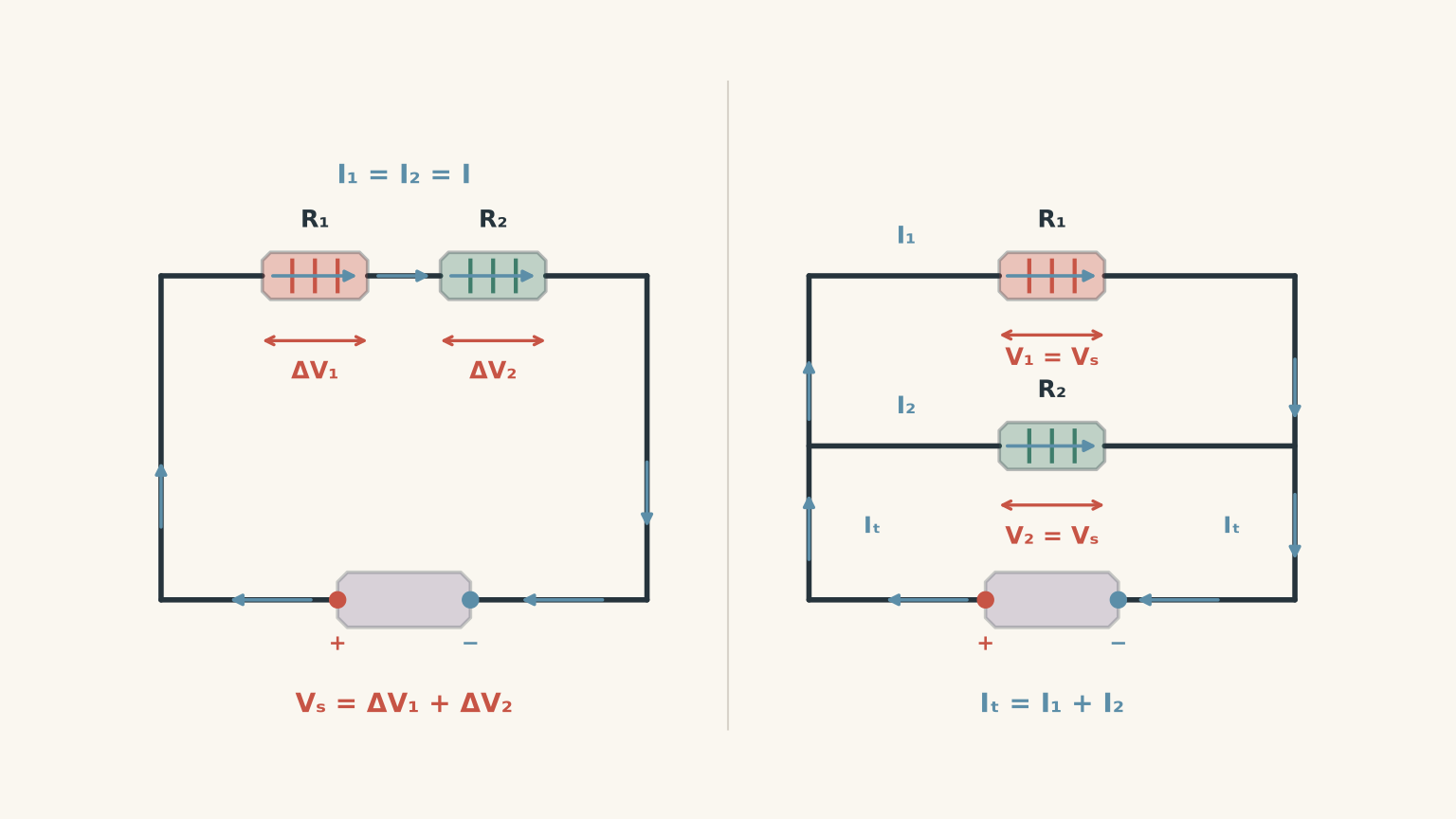
In a parallel network, each branch connects across the same two points. Therefore, each branch has the full source potential difference.
\[ V_6=V_3=12.0\,\text{V} \]
Answer: \(12.0\,\text{V}\) across each resistor.
(b) Current through each resistor
Apply Ohm’s law separately to each branch.
For the \(6.0\,\Omega\) resistor:
\[ I_6=\frac{12.0}{6.0}=2.0\,\text{A} \]
For the \(3.0\,\Omega\) resistor:
\[ I_3=\frac{12.0}{3.0}=4.0\,\text{A} \]
Answers: \(2.0\,\text{A}\) through the \(6.0\,\Omega\) resistor and \(4.0\,\text{A}\) through the \(3.0\,\Omega\) resistor.
The lower-resistance branch carries more current because both branches have the same potential difference.
(c) Total current supplied by the source
Kirchhoff’s current law states that the total current entering a junction equals the total current leaving it.
The source current is the sum of the branch currents:
\[ \begin{aligned} I_{\text{total}} &= I_6+I_3\\ &= 2.0+4.0\\ &= 6.0\,\text{A} \end{aligned} \]
Answer: \(6.0\,\text{A}\).
(d) Equivalent resistance
The equivalent resistance is the resistance of a single resistor that would draw the same total current from the same source.
\[ \begin{aligned} R_{\text{eq}} &= \frac{V}{I_{\text{total}}}\\ &= \frac{12.0}{6.0}\\ &= 2.0\,\Omega \end{aligned} \]
Answer: \(2.0\,\Omega\).
Notice that the equivalent resistance is lower than either individual branch resistance. Adding a parallel path allows more total current to flow for the same source voltage.
Marking guide – 8 marks
- (a) 1 mark: Correct potential difference across the \(6.0\,\Omega\) resistor; 1 mark: correct potential difference across the \(3.0\,\Omega\) resistor.
- (b) 1 mark: Correct current through each branch, with the mark awarded per correct value.
- (c) 1 mark: Correct addition of branch currents using current conservation; 1 mark: \(6.0\,\text{A}\).
- (d) 1 mark: Correct equivalent-resistance method; 1 mark: \(2.0\,\Omega\).
Solution 3
(a) Equivalent resistance of the parallel section
For two resistors in parallel, the reciprocal-resistance relationship is
\[ \frac{1}{R_p}=\frac{1}{R_1}+\frac{1}{R_2} \]
Substitute the two branch resistances:
\[ \begin{aligned} R_p &=\left(\frac{1}{6.0}+\frac{1}{3.0}\right)^{-1}\\ &=2.0\,\Omega \end{aligned} \]
Answer: \(2.0\,\Omega\).
An alternative is the product-over-sum relationship for two parallel resistors:
\[ R_p=\frac{R_1R_2}{R_1+R_2} \]
(b) Total equivalent resistance
The \(4.0\,\Omega\) resistor is in series with the equivalent resistance of the parallel section.
\[ \begin{aligned} R_{\text{total}} &= 4.0+2.0\\ &=6.0\,\Omega \end{aligned} \]
Answer: \(6.0\,\Omega\).
(c) Total current supplied by the source
Use the source voltage and total equivalent resistance.
\[ \begin{aligned} I_{\text{total}} &= \frac{V}{R_{\text{total}}}\\ &= \frac{20.0}{6.0}\\ &=3.33\,\text{A} \end{aligned} \]
Answer: \(3.33\,\text{A}\).
(d) Potential difference across the parallel section
The same total current passes through the series resistor and into the parallel section. The potential difference across the parallel section is
\[ \begin{aligned} V_p &= I_{\text{total}}R_p\\ &= \frac{20.0}{6.0}\times 2.0\\ &=6.67\,\text{V} \end{aligned} \]
Answer: \(6.67\,\text{V}\).
As a check, the \(4.0\,\Omega\) resistor has a potential difference of approximately \(13.3\,\text{V}\). Together, the two sections account for the \(20.0\,\text{V}\) source.
(e) Current through each parallel branch
Both branches have the same potential difference, \(6.67\,\text{V}\).
For the \(6.0\,\Omega\) resistor:
\[ I_6=\frac{6.67}{6.0}=1.11\,\text{A} \]
For the \(3.0\,\Omega\) resistor:
\[ I_3=\frac{6.67}{3.0}=2.22\,\text{A} \]
Answers: approximately \(1.11\,\text{A}\) through the \(6.0\,\Omega\) resistor and \(2.22\,\text{A}\) through the \(3.0\,\Omega\) resistor.
Check current conservation:
\[ 1.11+2.22\approx3.33\,\text{A} \]
The branch currents add to the total current, allowing for rounding.
Marking guide – 9 marks
- (a) 1 mark: Correct parallel-resistance relationship; 1 mark: \(2.0\,\Omega\).
- (b) 1 mark: \(6.0\,\Omega\).
- (c) 1 mark: Correct use of \(I=V/R\); 1 mark: \(3.33\,\text{A}\).
- (d) 1 mark: \(6.67\,\text{V}\).
- (e) 1 mark: Correct use of the branch potential difference and \(I=V/R\); 1 mark: \(1.11\,\text{A}\) through the \(6.0\,\Omega\) resistor; 1 mark: \(2.22\,\text{A}\) through the \(3.0\,\Omega\) resistor.
Follow-through marks should be awarded for correct methods using an earlier numerical result, even if that result was incorrect.
Solution 4
(a) Unknown current at the junction
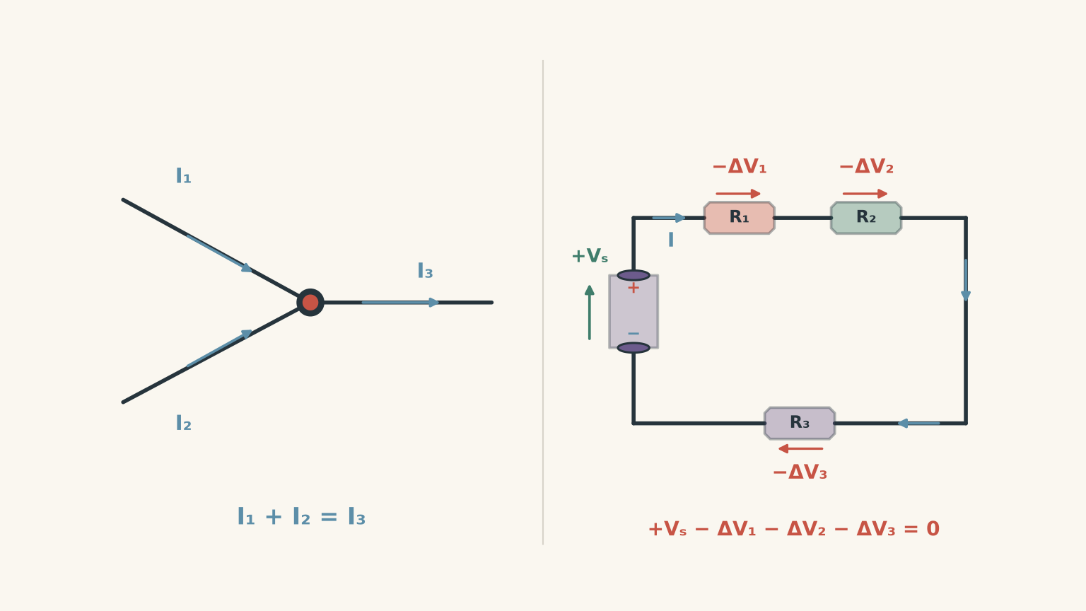
Kirchhoff’s current law requires the total current entering the junction to equal the total current leaving it.
The entering current is
\[ I_{\text{in}}=1.80+0.65=2.45\,\text{A} \]
Equating entering and leaving currents gives
\[ \begin{aligned} 2.45 &= 0.90+I\\ I &= 2.45-0.90\\ &=1.55\,\text{A} \end{aligned} \]
Answer: \(1.55\,\text{A}\).
The current is not consumed at the junction. Charge is conserved, so the total rate at which charge arrives must equal the total rate at which it leaves.
(b) Unknown potential drop
Kirchhoff’s voltage law states that the algebraic sum of potential changes around a closed loop is zero.
The source potential rise must equal the sum of the resistor potential drops:
\[ \begin{aligned} 12.0 &= 4.5+2.0+V_x\\ V_x &= 12.0-4.5-2.0\\ &=5.5\,\text{V} \end{aligned} \]
Answer: \(5.5\,\text{V}\).
The three drops add to \(12.0\,\text{V}\), matching the source potential rise.
(c) Conservation principles
(i) Kirchhoff’s current law follows from conservation of charge. Charge does not accumulate at an ordinary circuit junction.
(ii) Kirchhoff’s voltage law follows from conservation of energy. A charge completing a closed loop has no net change in energy after accounting for all potential rises and drops.
Marking guide – 6 marks
- (a) 1 mark: Correct current-balance equation; 1 mark: \(1.55\,\text{A}\).
- (b) 1 mark: Correct loop equation; 1 mark: \(5.5\,\text{V}\).
- (c) 1 mark: Conservation of charge for Kirchhoff’s current law; 1 mark: conservation of energy for Kirchhoff’s voltage law.
Solution 5
(a) Total resistance and source current
The resistors are in series, so their resistances add.
\[ \begin{aligned} R_{\text{total}} &= 4.0+8.0\\ &=12.0\,\Omega \end{aligned} \]
The source current is
\[ \begin{aligned} I &= \frac{V}{R_{\text{total}}}\\ &= \frac{24.0}{12.0}\\ &=2.0\,\text{A} \end{aligned} \]
Answers: \(12.0\,\Omega\) total resistance and \(2.0\,\text{A}\) source current.
(b) Power dissipated by the \(8.0\,\Omega\) resistor
Use the current through the resistor and the relationship \(P=I^2R\).
\[ \begin{aligned} P_8 &= I^2R_8\\ &=(2.0)^2\times8.0\\ &=32\,\text{W} \end{aligned} \]
Answer: \(32\,\text{W}\).
(c) New source current
After the \(8.0\,\Omega\) resistor is replaced with a \(4.0\,\Omega\) resistor, the two series resistances are both \(4.0\,\Omega\).
The new total resistance is
\[ R'_{\text{total}}=4.0+4.0=8.0\,\Omega \]
Therefore,
\[ \begin{aligned} I' &= \frac{24.0}{8.0}\\ &=3.0\,\text{A} \end{aligned} \]
Answer: \(3.0\,\text{A}\).
Reducing the total resistance while keeping the source voltage constant increases the current.
(d) New power and comparison
The replacement resistor has a resistance of \(4.0\,\Omega\), and the new series current is \(3.0\,\text{A}\).
\[ \begin{aligned} P' &= (I')^2R'\\ &=(3.0)^2\times4.0\\ &=36\,\text{W} \end{aligned} \]
The replacement resistor dissipates \(36\,\text{W}\), compared with \(32\,\text{W}\) for the original \(8.0\,\Omega\) resistor. This is an increase of \(4\,\text{W}\), or \(12.5\%\).
Why does the power increase when the resistance decreases? Because the current also changes. The current rises from \(2.0\,\text{A}\) to \(3.0\,\text{A}\), while the resistor’s resistance halves.
Since \(P=I^2R\), the power ratio is
\[ \begin{aligned} \frac{P'}{P_8} &=\left(\frac{3.0}{2.0}\right)^2 \left(\frac{4.0}{8.0}\right)\\ &=1.125 \end{aligned} \]
The increased current more than offsets the reduction in resistance, producing the \(12.5\%\) increase in power.
Marking guide – 10 marks
- (a) 1 mark: \(12.0\,\Omega\); 1 mark: correct current calculation; 1 mark: \(2.0\,\text{A}\).
- (b) 1 mark: Correct power relationship and substitution; 1 mark: \(32\,\text{W}\).
- (c) 1 mark: New total resistance of \(8.0\,\Omega\); 1 mark: new current of \(3.0\,\text{A}\).
- (d) 1 mark: \(36\,\text{W}\); 1 mark: correct comparison with the original power; 1 mark: explanation using the changes in current and resistance.
Accept mathematically equivalent methods, including \(P=VI\) or \(P=V^2/R\), when the required component values are correctly determined. Follow-through marks apply to consistent calculations using earlier results.
Solution 6
(a) Total equivalent resistance
Use the source voltage and the measured main-line current.
\[ \begin{aligned} R_{\text{total}} &= \frac{V}{I_{\text{total}}}\\ &=\frac{15.0}{3.0}\\ &=5.0\,\Omega \end{aligned} \]
Answer: \(5.0\,\Omega\).
(b) Equivalent resistance of the parallel section
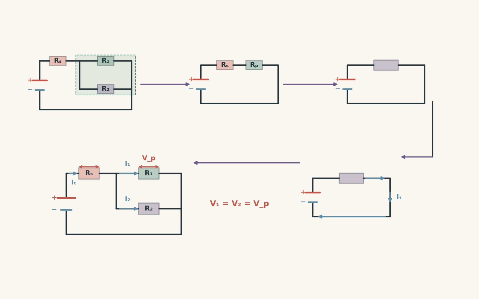
The \(2.0\,\Omega\) resistor is in series with the parallel section. Their equivalent resistances therefore add.
\[ \begin{aligned} R_{\text{parallel}} &= R_{\text{total}}-2.0\\ &=5.0-2.0\\ &=3.0\,\Omega \end{aligned} \]
Answer: \(3.0\,\Omega\).
(c) Potential differences across the two sections
First, calculate the potential difference across the \(2.0\,\Omega\) series resistor.
\[ \begin{aligned} V_2 &= IR\\ &=3.0\times2.0\\ &=6.0\,\text{V} \end{aligned} \]
The source potential difference is \(15.0\,\text{V}\). Applying conservation of energy around the loop, the potential difference across the parallel section is
\[ \begin{aligned} V_{\text{parallel}} &=15.0-6.0\\ &=9.0\,\text{V} \end{aligned} \]
Answers: \(6.0\,\text{V}\) across the series resistor and \(9.0\,\text{V}\) across the parallel section.
(d) Current through each parallel branch
Both parallel branches have a potential difference of \(9.0\,\text{V}\).
For the \(6.0\,\Omega\) branch:
\[ I_6=\frac{9.0}{6.0}=1.5\,\text{A} \]
Apply Kirchhoff’s current law to find the current through the unknown-resistance branch.
\[ \begin{aligned} I_{\text{total}} &= I_6+I_R\\ I_R &=3.0-1.5\\ &=1.5\,\text{A} \end{aligned} \]
Answers: \(1.5\,\text{A}\) through each branch.
The branch currents add to the measured main-line current, as required by conservation of charge.
(e) Unknown resistance \(R\)
Apply Ohm’s law to the unknown-resistance branch.
\[ \begin{aligned} R &=\frac{V_{\text{parallel}}}{I_R}\\ &=\frac{9.0}{1.5}\\ &=6.0\,\Omega \end{aligned} \]
Answer: \(6.0\,\Omega\).
The two parallel resistors have equal resistance, so they carry equal currents when connected across the same potential difference.
(f) Power dissipated by \(R\)
Use the potential difference and current for the unknown-resistance branch.
\[ \begin{aligned} P_R &=V_{\text{parallel}}I_R\\ &=9.0\times1.5\\ &=13.5\,\text{W} \end{aligned} \]
Answer: \(13.5\,\text{W}\).
You can verify this using \(P=I^2R\):
\[ P_R=(1.5)^2\times6.0=13.5\,\text{W} \]
Both methods give the same result.
Marking guide – 10 marks
- (a) 1 mark: \(5.0\,\Omega\).
- (b) 1 mark: Correct subtraction of the series resistance; 1 mark: \(3.0\,\Omega\).
- (c) 1 mark: \(6.0\,\text{V}\) across the series resistor; 1 mark: \(9.0\,\text{V}\) across the parallel section.
- (d) 1 mark: \(1.5\,\text{A}\) through the \(6.0\,\Omega\) branch; 1 mark: \(1.5\,\text{A}\) through the unknown-resistance branch.
- (e) 1 mark: Correct use of \(R=V/I\); 1 mark: \(6.0\,\Omega\).
- (f) 1 mark: \(13.5\,\text{W}\), calculated using a valid power relationship.
End of paper. Total: 50 marks.
When reviewing your work, focus on whether you chose the correct relationship for each part of the network. In combination circuits, reduce the network carefully, calculate the total current, and then return to the individual components. Use Kirchhoff’s laws to check that your final currents and potential differences satisfy conservation of charge and energy.