
Evidence for Light Models: HSC Physics Practice Exam
An original 40-mark timed practice paper focused on evidence for light models in the NSW HSC Physics 2017 syllabus. Includes six questions, full worked solutions, and a detailed marking guide.
This original tutorgum practice paper tests evidence for competing models of light in the NSW HSC Physics 2017 syllabus. It focuses on Huygens’ wave model, wavefront construction, and the evidence supporting wave behaviour, alongside Newton’s corpuscular model and its limitations.
The paper contains 40 marks across six questions. Attempt every question before moving to the worked solutions and marking guide.
01Exam instructions
This is an original tutorgum practice paper. It is not an official, endorsed, past, or predicted NESA examination paper.
Assessed syllabus scope
- Huygens’ wave model of light, including wavefront construction and evidence favouring waves.
- Newton’s corpuscular model, including its predictions, supporting evidence, and limitations.
- Comparison of the explanatory strengths and limitations of the two models.
- Connecting experimental observations to claims about the nature of light.
Excluded content
This paper does not assess the photoelectric effect, photons, quantum models of light, the electromagnetic spectrum, polarisation, or other syllabus topics outside the specified scope.
Practice examination conditions
| Condition | Requirement |
|---|---|
| Suggested reading time | 5 minutes |
| Suggested working time | 55 minutes |
| Total marks | 40 |
| Questions | 6 |
| Equipment | Scientific calculator, ruler, compass, pencil, eraser, and black or blue pen |
| Notes | Not permitted |
These are conditions for this practice paper, not claims about current official examination rules.
Assume that all media are homogeneous and that boundaries are ideal unless stated otherwise. Use the supplied numerical values, show all working, and include appropriate units.
All diagrams are schematic unless dimensions or a drawing scale are specified.
02Questions
Question 1 (6 marks)
Newton’s corpuscular model describes light as a stream of tiny particles, or corpuscles, emitted by luminous objects.
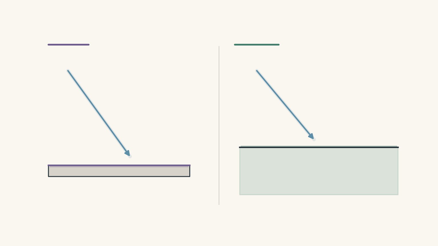
(a) Describe the central idea of Newton’s corpuscular model. Explain how it accounts for the straight-line propagation of light and reflection from a smooth surface. (2 marks)
(b) According to Newton’s model, what happens to the speed and direction of light when it travels from air into glass? (2 marks)
(c) Identify one observed behaviour of light that Newton’s basic corpuscular model does not explain adequately. Explain why this observation presents a problem for the model. (2 marks)
Question 2 (8 marks)
Huygens’ wave model describes the propagation of light using wavefronts and secondary wavelets.
Consider a plane wavefront travelling through air towards a boundary with glass.
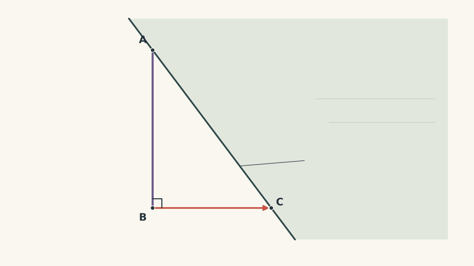
At \(t=0\), point A is the first point of the incident wavefront to reach the interface. Point B reaches point C after \(1.00\ \text{ns}\).
The relevant speeds are:
- Speed of light in air: \(3.00 \times 10^8\ \text{m s}^{-1}\)
- Speed of light in glass: \(2.00 \times 10^8\ \text{m s}^{-1}\)
(a) Define a wavefront. (1 mark)
(b) Calculate the radius of the secondary wavelet produced at point A during the \(1.00\ \text{ns}\) interval. (2 marks)
(c) Complete the Huygens construction on a copy of the diagram.
Use a drawing scale of \(1.0\ \text{cm} = 0.10\ \text{m}\), if required. Draw the secondary wavelet at A, construct the new refracted wavefront through C, and indicate the direction of propagation. Include the normal at C. (3 marks)
(d) Explain how the Huygens construction accounts for the change in direction of light when it enters glass from air. (2 marks)
Question 3 (8 marks)
A monochromatic light source illuminates two narrow, closely spaced slits. Light passes through both slits and reaches a screen.
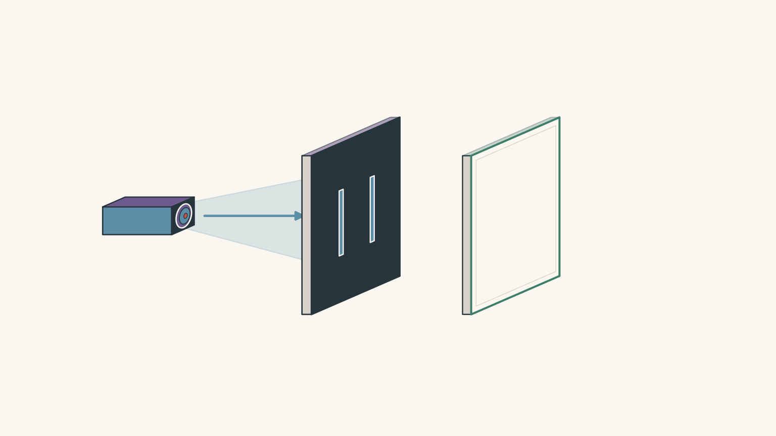
The two slits act as coherent sources, meaning that the waves they produce maintain a constant phase relationship.
The following observations are recorded on the screen. Position \(x=0\) represents the centre of the screen.
| Observation | Screen position, \(x\) |
|---|---|
| Bright bands | \(-8,\ -4,\ 0,\ 4,\ 8\) mm |
| Dark bands | \(-6,\ -2,\ 2,\ 6\) mm |
(a) Describe the pattern observed on the screen. (2 marks)
(b) Using Huygens’ wave model, explain how the bright and dark bands are produced. (4 marks)
(c) Explain why this observation provides evidence favouring a wave model of light over Newton’s corpuscular model. (2 marks)
Question 4 (6 marks)
Diffraction describes the spreading of light as it passes through an opening or around an obstacle.
An experiment is performed using the same monochromatic light source and two different slit widths.
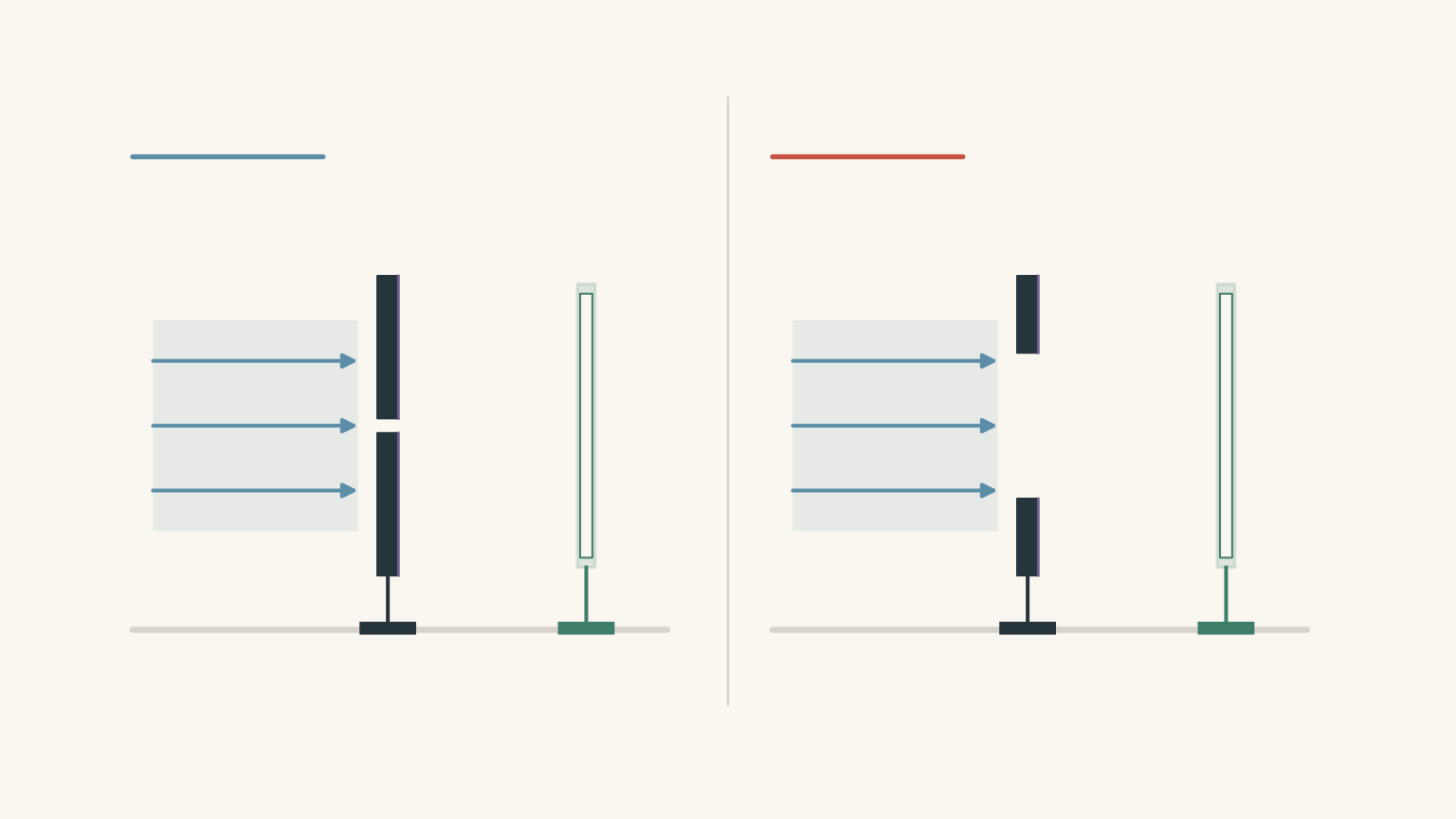
The observations are:
- The 0.20 mm opening produces a relatively wide illuminated region on the screen.
- The 2.0 mm opening produces a much narrower illuminated region.
(a) Define diffraction. (1 mark)
(b) Explain why the narrower opening produces greater spreading of light, using Huygens’ wave model. (3 marks)
(c) Explain why the observed spreading provides evidence favouring the wave model over a simple corpuscular model. (2 marks)
Question 5 (7 marks)
One way to compare Newton’s and Huygens’ models is to investigate how the speed of light changes when it enters a different medium.
A simplified experimental data set gives the following measured speeds.
| Medium | Measured speed of light |
|---|---|
| Air | \(3.00 \times 10^8\ \text{m s}^{-1}\) |
| Water | \(2.25 \times 10^8\ \text{m s}^{-1}\) |
(a) Calculate the percentage decrease in the speed of light when it travels from air into water. (2 marks)
(b) Compare the experimental result with the predictions of Newton’s corpuscular model and Huygens’ wave model. Identify which model is better supported by this evidence. (3 marks)
(c) A student concludes:
“The experimental result proves that Huygens’ wave model is correct.”
Explain why the word proves is too strong, while still acknowledging the significance of the experimental evidence. (2 marks)
Question 6 (5 marks)
A student makes the following argument:
“Newton’s model is just as strong as Huygens’ model because it explains why light travels in straight lines and reflects from mirrors. The other observations are not important.”
Evaluate this argument by comparing the explanatory strengths and limitations of Newton’s corpuscular model and Huygens’ wave model.
Refer to at least two distinct observations from Questions 3-5 in your response. (5 marks)
03Worked solutions and marking guide
Solution 1
(a) Newton’s corpuscular model (2 marks)
Newton proposed that luminous objects emit tiny particles called corpuscles.
These particles travel in straight lines through a uniform medium. When they encounter a smooth reflecting surface, an interaction with the surface redirects them, producing reflection.
The model therefore provides an explanation for two familiar observations:
- Light travels in straight lines through a uniform medium.
- Light can reflect from a smooth surface.
Marking guide:
- 1 mark for identifying light as particles emitted by luminous sources, travelling in straight lines.
- 1 mark for explaining reflection as the redirection or rebound of corpuscles at a surface.
(b) Refraction according to Newton (2 marks)
Newton’s model proposed that corpuscles experience an attractive force when approaching an optically denser medium.
When light enters glass from air, this attraction increases the component of particle velocity perpendicular to the boundary.
Newton’s model therefore predicts:
- Light bends towards the normal.
- Light travels faster in glass than in air.
This speed prediction is particularly important when comparing Newton’s model with experimental measurements.
Marking guide:
- 1 mark for predicting that light bends towards the normal.
- 1 mark for predicting that its speed increases in glass.
(c) Limitations of the corpuscular model (2 marks)
One important limitation is its difficulty explaining diffraction.
When light passes through a narrow opening, it spreads into regions that a simple straight-line particle model would predict to be in shadow.
A basic model of particles travelling along straight paths does not naturally explain this spreading.
Interference is another acceptable example. In a double-slit experiment, alternating bright and dark bands appear because waves reinforce and cancel one another. The basic corpuscular model does not naturally account for this pattern.
Marking guide:
- 1 mark for identifying a relevant observation, such as diffraction or interference.
- 1 mark for explaining why that observation is difficult to account for using the basic corpuscular model.
Solution 2
(a) Definition of a wavefront (1 mark)
A wavefront is a line or surface joining points on a wave that are in the same phase.
For example, all points on a particular crest belong to the same wavefront.
(b) Radius of the secondary wavelet (2 marks)
According to Huygens’ principle, each point on a wavefront acts as a source of secondary wavelets.
The radius of a secondary wavelet is the distance travelled by the wave during the specified time interval.
The relationship is:
\[ r=v\Delta t \]
where:
- \(r\) is the wavelet radius, measured in metres.
- \(v\) is the wave speed in the new medium, measured in metres per second.
- \(\Delta t\) is the time interval, measured in seconds.
The wavelet travels through glass, so we use the speed of light in glass.
Substituting:
\[ \begin{aligned} r &=v_{\text{glass}}\Delta t\\ &=(2.00\times10^8) (1.00\times10^{-9})\\ &=0.200\ \text{m} \end{aligned} \]
The radius is:
\[ \boxed{r=0.200\ \text{m}} \]
Marking guide:
- 1 mark for selecting the correct relationship and substituting the glass speed and time.
- 1 mark for obtaining \(0.200\ \text{m}\).
(c) Huygens construction (3 marks)
The construction follows three steps.
- Draw a secondary wavelet centred at A with a radius of \(0.200\ \text{m}\). Using the supplied scale, this corresponds to \(2.0\ \text{cm}\).
- Draw the forward tangent from C to the secondary wavelet. This tangent represents the new refracted wavefront.
- Draw the refracted direction of propagation perpendicular to the new wavefront, together with the normal to the interface at C.
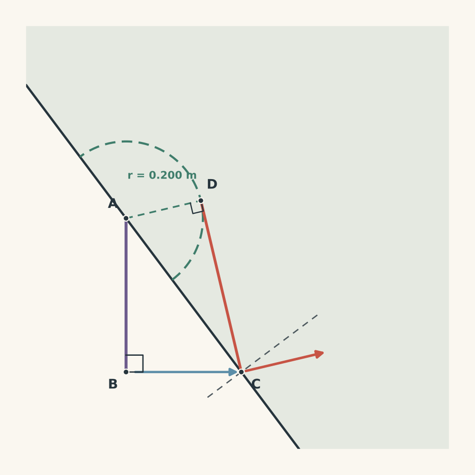
Marking guide:
- 1 mark for a correctly centred secondary wavelet with the appropriate radius.
- 1 mark for the correctly constructed tangent representing the new wavefront.
- 1 mark for identifying the refracted propagation direction as perpendicular to the new wavefront and directed into glass.
(d) Explaining the change in direction (2 marks)
Light travels more slowly in glass than in air.
During the same \(1.00\ \text{ns}\) interval:
- The point B travels \(0.30\ \text{m}\) through air.
- The secondary wavelet from A travels only \(0.20\ \text{m}\) through glass.
The different distances travelled cause the new wavefront to rotate relative to the original wavefront.
Because the direction of propagation is perpendicular to the wavefront, this rotation changes the direction of the refracted ray.
The ray bends towards the normal when entering the slower medium.
Marking guide:
- 1 mark for explaining that the slower wave speed produces a smaller secondary wavelet radius during the same time interval.
- 1 mark for linking the rotated wavefront to propagation towards the normal.
Solution 3
(a) Observed interference pattern (2 marks)
The screen displays alternating bright and dark bands.
The pattern is symmetrical about the centre, with a central bright band at \(x=0\). The bright and dark bands occur at regular intervals.
This is known as an interference pattern.
Marking guide:
- 1 mark for identifying alternating bright and dark bands.
- 1 mark for identifying the regular spacing or symmetry about the central bright band.
(b) Explaining the pattern using the wave model (4 marks)
Huygens’ wave model describes light from each slit as spreading outwards through secondary wavelets.
The waves from the two slits overlap when they reach the screen. This produces interference.
There are two important types of interference.
- Constructive interference
Constructive interference occurs when two waves arrive in phase.
Their amplitudes reinforce one another, producing a greater intensity of light. This creates a bright band.
- Destructive interference
Destructive interference occurs when two waves arrive out of phase.
Their amplitudes cancel, reducing the intensity of light. This creates a dark band.
The relationship between path difference and interference can be written as:
\[ \begin{aligned} \text{Bright: } \Delta L &=m\lambda\\ \text{Dark: } \Delta L &= \left(m+\frac12\right)\lambda \end{aligned} \]
Here:
- \(\Delta L\) is the difference between the distances travelled by the two waves.
- \(\lambda\) is the wavelength of light.
- \(m\) is an integer.
As the position on the screen changes, the path difference changes. This produces alternating regions of constructive and destructive interference.
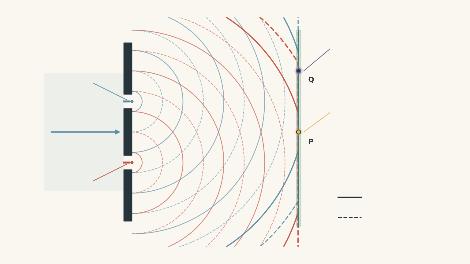
Marking guide:
- 1 mark for explaining that waves from the two slits spread and overlap.
- 1 mark for explaining constructive interference and the resulting bright bands.
- 1 mark for explaining destructive interference and the resulting dark bands.
- 1 mark for connecting the repeated interference to the alternating pattern.
(c) Evidence against Newton’s model (2 marks)
Newton’s corpuscular model describes light as particles travelling along straight paths.
Although this model can account for light passing through the slits, it does not naturally explain why certain regions of the screen become dark while others become bright.
In particular, it cannot adequately explain the cancellation of light associated with destructive interference.
The alternating pattern is therefore strong evidence favouring a wave model.
Marking guide:
- 1 mark for identifying the difficulty of explaining alternating bright and dark bands using the basic corpuscular model.
- 1 mark for linking constructive and destructive interference to evidence of wave behaviour.
Solution 4
(a) Definition of diffraction (1 mark)
Diffraction is the spreading of waves as they pass through an opening or around an obstacle.
(b) Explaining the difference in spreading (3 marks)
According to Huygens’ principle, every point on a wavefront acts as a source of secondary wavelets.
When light passes through an opening, these wavelets spread out from the opening and combine to form a new wavefront.
The amount of diffraction depends on the wavelength relative to the opening width.
For the two experiments:
- The \(0.20\ \text{mm}\) opening is narrower, so the light spreads through a greater angle.
- The \(2.0\ \text{mm}\) opening is wider, so the light spreads through a smaller angle.
The narrower opening therefore produces a wider illuminated region on the screen.
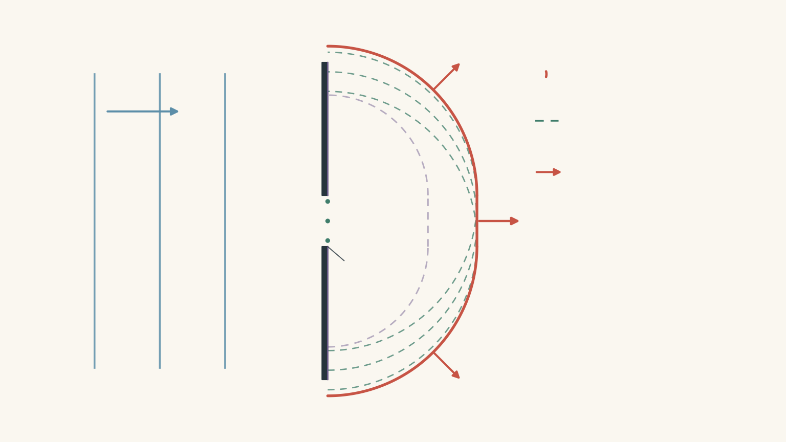
Marking guide:
- 1 mark for identifying that the narrower opening produces greater angular spreading.
- 1 mark for explaining the role of secondary wavelets at the opening.
- 1 mark for linking the relative opening width to the observed difference in diffraction.
(c) Evidence favouring the wave model (2 marks)
A simple corpuscular model predicts that particles travelling in straight lines should continue mainly in the forward direction after passing through an opening.
It does not naturally explain why light spreads into regions outside the direct path.
The observed diffraction is therefore evidence supporting the wave model.
Marking guide:
- 1 mark for identifying that diffraction involves spreading beyond the direct path.
- 1 mark for explaining why this behaviour is difficult to account for using a simple straight-line corpuscular model.
Solution 5
(a) Percentage decrease in speed (2 marks)
We are given:
\[ v_{\text{air}}=3.00\times10^8 \]
\[ v_{\text{water}}=2.25\times10^8 \]
The percentage decrease is calculated using:
\[ \%\text{ decrease} = \frac{v_{\text{air}}-v_{\text{water}}} {v_{\text{air}}}\times100 \]
Substituting:
\[ \begin{aligned} \%\text{ decrease} &=\frac{3.00-2.25}{3.00}\times100\\ &=\frac{0.75}{3.00}\times100\\ &=25.0\% \end{aligned} \]
Therefore:
\[ \boxed{\text{Percentage decrease}=25.0\%} \]
The speed of light decreases by 25.0% when entering water from air.
Marking guide:
- 1 mark for correctly setting up the percentage decrease calculation.
- 1 mark for obtaining \(25.0\%\).
(b) Comparing the two models (3 marks)
The experimental result shows that light travels more slowly in water than in air.
This agrees with Huygens’ wave model.
Huygens’ model predicts that light travels more slowly in an optically denser medium. This change in speed also explains why light bends towards the normal when entering that medium.
Newton’s corpuscular model makes the opposite prediction for the speed.
Newton proposed that the attractive force experienced by corpuscles entering a denser medium increases their speed.
Therefore, the experimental observation contradicts Newton’s predicted increase in speed but agrees with Huygens’ prediction of a decrease.
Huygens’ wave model is better supported by this particular experiment.
Marking guide:
- 1 mark for identifying that the measured speed decreases in water.
- 1 mark for explaining that this agrees with Huygens’ prediction.
- 1 mark for explaining that this contradicts Newton’s prediction of increased speed.
(c) Evidence versus proof (2 marks)
The word proves is too strong because a single experimental result cannot establish that an entire scientific model is correct.
This experiment tests one particular prediction about the speed of light in different media.
The result strongly supports Huygens’ model because it agrees with its prediction and contradicts Newton’s prediction.
However, a scientific model must be assessed against a wider range of observations and experimental evidence.
Marking guide:
- 1 mark for explaining that one experiment tests only a limited part of a model and cannot establish all its predictions.
- 1 mark for acknowledging that the result nevertheless favours Huygens’ model over Newton’s prediction.
Solution 6
Newton’s corpuscular model has genuine explanatory strengths.
It accounts for light travelling in straight lines through a uniform medium and provides an explanation for reflection from smooth surfaces. It also predicts that light bends towards the normal when entering a denser medium.
However, these successes do not mean that the model explains every observation.
The double-slit experiment in Question 3 demonstrates interference. Alternating bright and dark bands arise from constructive and destructive interference, which the basic corpuscular model does not naturally explain.
The diffraction experiment in Question 4 also favours wave behaviour. Light spreads after passing through a narrow opening, whereas a simple straight-line particle model cannot adequately explain this spreading.
Finally, the measurements in Question 5 show that light travels more slowly in water than in air. This agrees with Huygens’ prediction but contradicts Newton’s prediction that light would travel faster in a denser medium.
Huygens’ wave model therefore provides a stronger overall explanation of the evidence considered in this paper.
Newton’s model should not be dismissed as having no explanatory value. It accounts for some observations, particularly straight-line propagation and reflection. However, its limitations become clear when considering interference, diffraction, and the measured speed of light in different media.
The strongest conclusion is that Huygens’ wave model is better supported by this collection of observations, not that one experiment or a limited set of experiments proves every aspect of a scientific model.
Marking guide:
- 1 mark for identifying a genuine explanatory strength of Newton’s model, such as straight-line propagation or reflection.
- 1 mark for explaining how Huygens’ model accounts for diffraction.
- 1 mark for explaining how Huygens’ model accounts for interference.
- 1 mark for using the speed measurements to distinguish the predictions of the two models.
- 1 mark for reaching a balanced conclusion that recognises the greater overall explanatory strength of Huygens’ model while acknowledging the successes of Newton’s model.
Total: 40 marks