
M4 Electricity and Magnetism: 75-Mark Physics Practice Exam
Test your understanding of the legacy NSW HSC Physics Module 4: Electricity and Magnetism with this original 75-mark timed practice paper. Includes exam instructions, mixed-difficulty questions, complete worked solutions, and a detailed marking guide.
This original tutorgum practice paper covers mixed revision across the supplied legacy NSW HSC Physics Module 4: Electricity and Magnetism scope associated with the 2017 syllabus edition. It is a focused topic assessment, not a full-course exam, and it is not an official, endorsed, past, or predicted NESA paper.
01Exam instructions
- Suggested working time: 90 minutes, plus 5 minutes of reading time.
- Total marks: 75.
- Permitted equipment: Scientific calculator and writing materials. No notes or internet access.
- Assessed topics: Charging processes, electrostatic forces and fields, electric potential and energy, current and charge flow, circuit analysis, electrical power and heating, magnetic fields, permanent magnets, and ferromagnetic materials.
- Exclusions: Content from other modules, later syllabus editions, and topics outside the supplied legacy assessment scope.
These are the conditions for this tutorgum practice paper, not a statement of current official examination rules.
Use SI units throughout. Show your working, include units in numerical answers, and give answers to two or three significant figures unless otherwise appropriate. Equivalent correct methods are acceptable.
Use the following constants where required:
\[ k=8.99\times10^9\ \mathrm{N\,m^2\,C^{-2}} \]
\[ e=1.60\times10^{-19}\ \mathrm C \]
\[ m_e=9.11\times10^{-31}\ \mathrm{kg} \]
\[ \mu_0=4\pi\times10^{-7}\ \mathrm{T\,m\,A^{-1}} \]
Assume air has the same permittivity as a vacuum. For a medium with relative permittivity \(\varepsilon_r\), use the simple model in which the electrostatic force magnitude is the corresponding air value divided by \(\varepsilon_r\).
02Questions
Question 1 (5 marks)
(a) Compare charging by friction with charging by contact. Identify the charge carriers that transfer between objects and one difference between the two processes. (2 marks)
(b) A neutral metal sphere rests on an insulating stand. A negatively charged rod is brought close to the sphere without touching it. While the rod remains nearby, the sphere is earthed. The earth connection is then removed before the rod is taken away.
State the final net charge on the sphere and explain how this charge develops. (2 marks)
(c) Explain why a charged balloon can attract an initially neutral wall. (1 mark)
Question 2 (6 marks)
Two point charges are separated by \(0.20\ \mathrm m\) in air:
- \(q_1=+3.0\ \mu\mathrm C\)
- \(q_2=-2.0\ \mu\mathrm C\)
(a) Calculate the magnitude of the electrostatic force between the charges. (2 marks)
(b) State the direction of the force acting on each charge. (1 mark)
(c) The second charge is replaced with \(q_2=+4.0\ \mu\mathrm C\), and the separation is increased to \(0.40\ \mathrm m\). Calculate the new force magnitude. (2 marks)
(d) Return to the original charges and separation. Estimate the force magnitude if the charges are placed in a medium with relative permittivity \(\varepsilon_r=4.0\). (1 mark)
Question 3 (4 marks)
A steady current of \(0.80\ \mathrm A\) flows through a metal wire for \(3.0\) minutes.
(a) Calculate the total charge passing a cross-section of the wire during this time. (2 marks)
(b) Calculate the number of electrons corresponding to this charge. (1 mark)
(c) State the direction of conventional current relative to the drift direction of electrons in the metal. (1 mark)
Question 4 (9 marks)
Two large parallel plates have a potential difference of \(600\ \mathrm V\) and are separated by \(0.030\ \mathrm m\). The electric field near the centre of the plates is approximately uniform and points from the positive plate towards the negative plate.
An electron begins halfway between the plates with an initial velocity of \(2.0\times10^6\ \mathrm{m\,s^{-1}}\) parallel to the plates. Ignore gravity.
(a) Calculate the magnitude of the electric field between the plates. (2 marks)
(b) Calculate the magnitude and direction of the electric force acting on the electron. (2 marks)
(c) Calculate the electron’s acceleration and its displacement perpendicular to its initial motion after \(2.0\ \mathrm{ns}\). (3 marks)
(d) Explain why the field is approximately uniform near the centre of the plates and describe what changes near their edges. (2 marks)
Question 5 (6 marks)
(a) A field-line representation of an isolated point charge \(P\) shows arrows directed radially inward. The lines are more densely spaced at location A than at location B.
Identify the sign of \(P\) and compare the electric field strengths at A and B. (2 marks)
(b) Two point charges, \(+Q\) and \(-Q\), have equal magnitudes. The positive charge is on the left and the negative charge is on the right.
At the midpoint between the charges, state the direction of the electric field contribution from each charge and the direction of the resultant field. (2 marks)
(c) For a field-line representation of this dipole, state where the lines begin and end, and explain what greater line density represents. (2 marks)
Question 6 (8 marks)
Two points in an electric field have electric potentials:
- Point A: \(120\ \mathrm V\)
- Point B: \(40\ \mathrm V\)
A positive charge of \(+2.0\ \mu\mathrm C\) moves from A to B.
(a) Calculate the potential difference \(V_B-V_A\). (1 mark)
(b) Calculate the change in the charge’s electric potential energy. Include the sign of your answer. (2 marks)
(c) Calculate the work done by the electric field on the positive charge. (1 mark)
(d) State how electric field lines meet equipotential lines. Explain whether the electric field does work when a charge moves along a single equipotential line. (2 marks)
(e) An electron moves from A to B. Calculate the change in its electric potential energy, including the sign. (2 marks)
Question 7 (10 marks)
An ideal \(12\ \mathrm V\) supply is connected to a \(2.0\ \Omega\) resistor, \(R_1\), in series with a parallel combination of two resistors:
- \(R_2=6.0\ \Omega\)
- \(R_3=3.0\ \Omega\)
Treat all resistors as ohmic.
(a) Calculate the equivalent resistance of the parallel combination and the total circuit resistance. (2 marks)
(b) Calculate the total current supplied by the battery. (1 mark)
(c) Calculate the potential difference across \(R_1\) and the potential difference across the parallel combination. (2 marks)
(d) Calculate the currents through \(R_2\) and \(R_3\). Use these currents to verify Kirchhoff’s current law at the junction. (2 marks)
(e) Use your voltage results to demonstrate that Kirchhoff’s voltage law is satisfied around a complete loop containing \(R_1\) and \(R_2\). (1 mark)
(f) Calculate the power dissipated in \(R_1\) and \(R_3\). (2 marks)
Question 8 (6 marks)
Two electrical devices are tested by measuring their current at different applied voltages. The results are shown below.
| Voltage (V) | Device A current (A) | Device B current (A) |
|---|---|---|
| 0.0 | 0.00 | 0.00 |
| 1.0 | 0.20 | 0.25 |
| 2.0 | 0.40 | 0.38 |
| 3.0 | 0.60 | 0.47 |
| 4.0 | 0.80 | 0.54 |
| 5.0 | 1.00 | 0.60 |
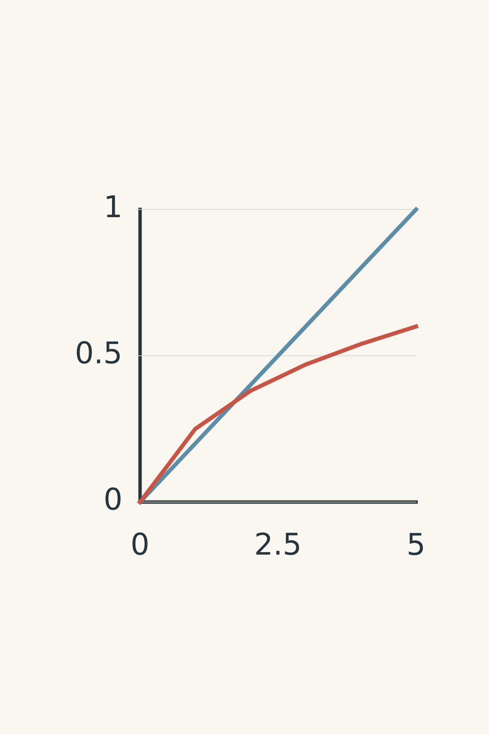
- Device A
- Device B
(a) Calculate the resistance of Device A when the applied voltage is \(3.0\ \mathrm V\). (1 mark)
(b) Identify which device obeys Ohm’s law over the measured range. Justify your answer using the data or graph. (2 marks)
(c) Calculate the resistance of Device B when the applied voltage is \(5.0\ \mathrm V\). (1 mark)
(d) Explain why the resistance of Device B changes as the current increases. (2 marks)
Question 9 (6 marks)
A kettle operates from a \(230\ \mathrm V\) supply and draws a steady current of \(8.0\ \mathrm A\) for \(4.0\) minutes. Treat the kettle’s heating element as a resistive device over this interval.
(a) Calculate the resistance of the heating element. (1 mark)
(b) Calculate the electrical power consumed by the kettle. (2 marks)
(c) Calculate the electrical energy transferred during the \(4.0\)-minute interval, in joules. (2 marks)
(d) Explain, in terms of charge carriers, why the heating element increases in temperature when current flows through it. (1 mark)
Question 10 (8 marks)
(a) A long, straight vertical wire carries a current of \(5.0\ \mathrm A\) upwards. Calculate the magnetic field magnitude at a point \(2.0\ \mathrm{cm}\) due east of the wire, using
\[ B=\frac{\mu_0 I}{2\pi r} \]
where \(B\) is magnetic field strength, \(I\) is current, and \(r\) is the distance from the wire. (2 marks)
(b) State the direction of the magnetic field at this point. (1 mark)
(c) An ideal solenoid has 800 turns over a length of \(0.40\ \mathrm m\) and carries a current of \(1.5\ \mathrm A\). Calculate the magnetic field strength inside the solenoid using
\[ B=\frac{\mu_0 NI}{L} \]
where \(N\) is the number of turns and \(L\) is the solenoid length. State what happens to the field strength if the turn density \(N/L\) doubles while the current remains constant. (3 marks)
(d) State the right-hand grip rule used to identify the north pole of a solenoid. (1 mark)
(e) State one qualitative difference between the magnetic field inside an ideal solenoid and the field outside it. (1 mark)
Question 11 (7 marks)
(a) State the direction of magnetic field lines outside a bar magnet. Explain what greater field-line density indicates. (2 marks)
(b) Two bar magnets are arranged in two different ways: first with unlike poles facing, and then with like poles facing. For each arrangement, predict whether the magnets attract or repel. Describe how the field-line pattern in the gap differs between the two arrangements. (2 marks)
(c) Explain the difference between a ferromagnetic material and a permanent magnet. (1 mark)
(d) Explain how magnetic domain alignment produces magnetisation. Distinguish induced magnetisation from retained magnetisation. (2 marks)
03Worked solutions and marking guide
Solution 1
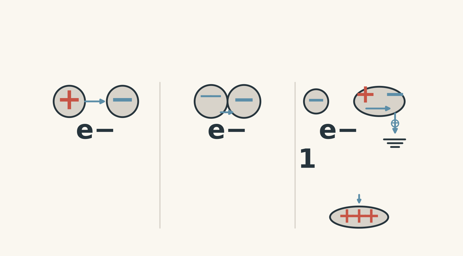
(a) Charging by friction and contact
In both processes, electrons transfer between materials.
When two materials are rubbed together, electrons may transfer from one material to the other because the materials interact differently with electrons. The objects are left with opposite net charges.
Charging by contact occurs when a charged object directly touches another object. Electrons transfer through the contact, and a previously neutral conductor generally acquires the same sign of charge as the charging object.
Marking (2 marks):
- 1 mark for identifying electrons as the charge carriers.
- 1 mark for distinguishing rubbing from direct contact.
(b) Charging by induction
The sphere becomes positively charged.
The negatively charged rod repels electrons in the sphere. When the sphere is earthed, some electrons flow from the sphere into the Earth. Removing the earth connection first prevents those electrons from returning when the rod is removed. The sphere is left with a net positive charge.
Marking (2 marks):
- 1 mark for identifying the final positive charge.
- 1 mark for explaining electron movement to Earth and the order of disconnection.
(c) Attraction between a charged balloon and a neutral wall
The balloon causes polarisation in the wall. Charges within the wall shift slightly, bringing an induced region of opposite charge closer to the balloon. The attraction between these closer opposite charges produces a net attractive force, even though the wall remains neutral overall.
Marking (1 mark):
- 1 mark for explaining attraction through polarisation or induced charge separation.
Solution 2
(a) Original force magnitude
The magnitude of the electrostatic force is approximately \(1.35\ \mathrm N\).
Coulomb’s law for two point charges in air is
\[ F=k\frac{|q_1q_2|}{r^2} \]
Substitute the magnitudes of the charges and their separation:
\[ \begin{aligned} F&=\frac{(8.99\times10^9) (3.0\times10^{-6})(2.0\times10^{-6})} {(0.20)^2}\\[4pt] &=1.3485\ \mathrm N\\[4pt] &\approx1.35\ \mathrm N \end{aligned} \]
The absolute value is used because this calculation gives the force magnitude. The signs of the charges determine the direction of the force.
Marking (2 marks):
- 1 mark for the correct Coulomb’s law substitution.
- 1 mark for the correct magnitude with unit.
(b) Force directions
The charges attract because they have opposite signs. The force on \(q_1\) points towards \(q_2\), while the force on \(q_2\) points towards \(q_1\).
Marking (1 mark):
- 1 mark for correctly identifying attraction and the directions of both forces.
(c) New force magnitude
The new force magnitude is approximately \(0.674\ \mathrm N\).
\[ \begin{aligned} F&=\frac{(8.99\times10^9) (3.0\times10^{-6})(4.0\times10^{-6})} {(0.40)^2}\\[4pt] &=0.67425\ \mathrm N\\[4pt] &\approx0.674\ \mathrm N \end{aligned} \]
Both charges are now positive, so they repel. The new force is half the original force magnitude.
This result makes sense: doubling one charge doubles the force, while doubling the separation reduces the force to one quarter of its previous value. The combined factor is \(2\times\frac14=\frac12\).
Marking (2 marks):
- 1 mark for the correct substitution or scaling argument.
- 1 mark for the correct force magnitude with unit.
(d) Force in the medium
The force magnitude is approximately \(0.338\ \mathrm N\).
\[ F_{\text{medium}} =\frac{F_{\text{air}}}{\varepsilon_r} =\frac{1.35}{4.0} =0.3375\ \mathrm N \]
To three significant figures, this is \(0.338\ \mathrm N\).
Marking (1 mark):
- 1 mark for correctly applying the relative permittivity factor.
Solution 3
(a) Total charge transferred
The total charge is \(144\ \mathrm C\).
Current is the rate of charge flow:
\[ I=\frac{q}{t} \]
Rearranging gives \(q=It\). First convert the time:
\[ t=3.0\times60=180\ \mathrm s \]
Then substitute:
\[ \begin{aligned} q&=(0.80)(180)\\ &=144\ \mathrm C \end{aligned} \]
Marking (2 marks):
- 1 mark for converting time correctly and using \(q=It\).
- 1 mark for the correct charge with unit.
(b) Number of electrons
The charge corresponds to approximately \(9.0\times10^{20}\) electrons.
Each electron has a charge magnitude of \(1.60\times10^{-19}\ \mathrm C\). Therefore,
\[ \begin{aligned} N&=\frac{q}{e}\\ &=\frac{144}{1.60\times10^{-19}}\\ &=9.0\times10^{20} \end{aligned} \]
Marking (1 mark):
- 1 mark for the correct number of electrons.
(c) Conventional current
Conventional current is opposite to the direction of electron drift in a metal.
Conventional current is defined as the direction in which positive charge would move. In a metal, the mobile charge carriers are electrons, which are negatively charged and drift in the opposite direction.
Marking (1 mark):
- 1 mark for identifying the opposite directions.
Solution 4
(a) Electric field magnitude
The electric field strength is \(2.0\times10^4\ \mathrm{V\,m^{-1}}\).
For a uniform field between parallel plates,
\[ E=\frac{V}{d} \]
where \(V\) is the potential difference and \(d\) is the plate separation.
\[ \begin{aligned} E&=\frac{600}{0.030}\\ &=2.0\times10^4\ \mathrm{V\,m^{-1}} \end{aligned} \]
Marking (2 marks):
- 1 mark for selecting \(E=V/d\).
- 1 mark for the correct field magnitude and unit.
(b) Electric force on the electron
The force magnitude is \(3.2\times10^{-15}\ \mathrm N\), directed towards the positive plate.
The magnitude of the electric force is
\[ F=|q|E \]
Using the electron charge magnitude,
\[ \begin{aligned} F&=(1.60\times10^{-19})(2.0\times10^4)\\ &=3.2\times10^{-15}\ \mathrm N \end{aligned} \]
The electric field points towards the negative plate. Because an electron has negative charge, its force is opposite to the field direction.
Marking (2 marks):
- 1 mark for the correct force calculation.
- 1 mark for the correct direction.
(c) Acceleration and displacement
The electron’s acceleration magnitude is approximately \(3.51\times10^{15}\ \mathrm{m\,s^{-2}}\). Its displacement perpendicular to its initial motion is approximately \(7.0\times10^{-3}\ \mathrm m\), towards the positive plate.
Newton’s second law gives
\[ F=ma \]
Therefore,
\[ \begin{aligned} a&=\frac{F}{m_e}\\ &=\frac{3.2\times10^{-15}} {9.11\times10^{-31}}\\ &=3.51\times10^{15}\ \mathrm{m\,s^{-2}} \end{aligned} \]
The electron initially has no velocity component perpendicular to the plates. Its displacement in that direction is therefore
\[ y=\frac12 at^2 \]
Convert the time:
\[ t=2.0\ \mathrm{ns}=2.0\times10^{-9}\ \mathrm s \]
Then
\[ \begin{aligned} y&=\frac12(3.51\times10^{15}) (2.0\times10^{-9})^2\\ &=7.02\times10^{-3}\ \mathrm m\\ &\approx7.0\ \mathrm{mm} \end{aligned} \]
The displacement is towards the positive plate, opposite to the electric field. The electron’s initial velocity parallel to the plates remains unchanged because the electric force acts perpendicular to that velocity.
Marking (3 marks):
- 1 mark for calculating acceleration.
- 1 mark for calculating displacement using the correct time.
- 1 mark for the displacement direction.
(d) Uniform field and edge effects
Near the centre of large parallel plates, the electric field is approximately uniform because the field lines are nearly parallel and equally spaced. Near the edges, the field lines curve outwards, producing fringing fields where the field is no longer uniform.
Marking (2 marks):
- 1 mark for explaining the approximately uniform central field.
- 1 mark for describing fringing and the resulting non-uniformity near the edges.
Solution 5
(a) Sign and relative field strength
Charge \(P\) is negative, and the field is stronger at A than at B.
Electric field lines point towards negative charges and away from positive charges. The inward arrows therefore identify \(P\) as negative.
In a field-line representation, greater line density indicates a stronger electric field. Since the lines are denser at A,
\[ E_A>E_B \]
Marking (2 marks):
- 1 mark for identifying the negative charge.
- 1 mark for comparing the field strengths correctly.
(b) Resultant field at the dipole midpoint
Both field contributions point to the right, so the resultant field also points to the right, from \(+Q\) towards \(-Q\).
At the midpoint, the field produced by \(+Q\) points away from the positive charge. This is to the right.
The field produced by \(-Q\) points towards the negative charge. This is also to the right.
Because both contributions point in the same direction, they add rather than cancel.
Marking (2 marks):
- 1 mark for correctly identifying the direction of both individual contributions.
- 1 mark for the resultant direction.
(c) Dipole field lines
The field lines begin at the positive charge and end at the negative charge. Greater line density represents a stronger electric field.
The field at any point is the vector sum of the contributions from both charges. The field-line pattern represents this combined field rather than either charge’s field in isolation.
Marking (2 marks):
- 1 mark for the correct start and end of the field lines.
- 1 mark for explaining the relationship between line density and field strength.
Solution 6
(a) Potential difference
The potential difference is \(-80\ \mathrm V\).
\[ \begin{aligned} \Delta V&=V_B-V_A\\ &=40-120\\ &=-80\ \mathrm V \end{aligned} \]
The negative sign means the electric potential decreases as the charge moves from A to B.
Marking (1 mark):
- 1 mark for the correct potential difference, including its sign.
(b) Change in electric potential energy
The positive charge’s electric potential energy decreases by \(1.6\times10^{-4}\ \mathrm J\).
Electric potential difference is the change in electric potential energy per unit charge:
\[ \Delta V=\frac{\Delta U}{q} \]
Rearranging,
\[ \Delta U=q\Delta V \]
Substituting,
\[ \begin{aligned} \Delta U&=(2.0\times10^{-6})(-80)\\ &=-1.6\times10^{-4}\ \mathrm J \end{aligned} \]
The negative result means the charge loses electric potential energy.
Marking (2 marks):
- 1 mark for using \(\Delta U=q\Delta V\).
- 1 mark for the correct signed result with unit.
(c) Work done by the electric field
The work done by the electric field is \(+1.6\times10^{-4}\ \mathrm J\).
For the charge moving from A to B,
\[ W_{\text{field}}=-\Delta U \]
Therefore,
\[ W_{\text{field}}=+1.6\times10^{-4}\ \mathrm J \]
The field does positive work because the positive charge moves towards lower electric potential and loses electric potential energy.
Marking (1 mark):
- 1 mark for the correct work, including its sign.
(d) Equipotential lines
Electric field lines meet equipotential lines at right angles.
Moving a charge along one equipotential produces no change in electric potential. Since \(\Delta V=0\), the work done by the electric field is
\[ W_{\text{field}}=-q\Delta V=0 \]
Marking (2 marks):
- 1 mark for identifying the perpendicular relationship.
- 1 mark for explaining why no work is done along an equipotential.
(e) Electron moving from A to B
The electron’s electric potential energy increases by \(1.28\times10^{-17}\ \mathrm J\).
The electron’s charge is negative:
\[ q=-1.60\times10^{-19}\ \mathrm C \]
Using the same potential difference,
\[ \begin{aligned} \Delta U&=q\Delta V\\ &=(-1.60\times10^{-19})(-80)\\ &=+1.28\times10^{-17}\ \mathrm J \end{aligned} \]
Both factors are negative, so the change in potential energy is positive. This is a useful reminder that moving to a lower electric potential does not always mean losing electric potential energy. The sign of the charge matters.
Marking (2 marks):
- 1 mark for using the signed electron charge.
- 1 mark for the correct positive change in potential energy with unit.
Solution 7
(a) Equivalent and total resistance
The equivalent resistance of the parallel pair is \(2.0\ \Omega\), giving a total resistance of \(4.0\ \Omega\).
For resistors in parallel,
\[ \frac{1}{R_p}=\frac{1}{R_2}+\frac{1}{R_3} \]
Substituting,
\[ \begin{aligned} \frac{1}{R_p}&=\frac16+\frac13\\ &=\frac12\\ R_p&=2.0\ \Omega \end{aligned} \]
The parallel combination is in series with \(R_1\), so
\[ \begin{aligned} R_{\text{total}}&=R_1+R_p\\ &=2.0+2.0\\ &=4.0\ \Omega \end{aligned} \]
Marking (2 marks):
- 1 mark for the correct equivalent parallel resistance.
- 1 mark for the correct total resistance.
(b) Total current
The total current is \(3.0\ \mathrm A\).
Using Ohm’s law for the complete circuit,
\[ \begin{aligned} I_{\text{total}}&=\frac{V}{R_{\text{total}}}\\ &=\frac{12}{4.0}\\ &=3.0\ \mathrm A \end{aligned} \]
Marking (1 mark):
- 1 mark for the correct current.
(c) Potential differences
The potential difference across \(R_1\) is \(6.0\ \mathrm V\). The potential difference across the parallel combination is also \(6.0\ \mathrm V\).
The current through \(R_1\) is the total current, so
\[ V_1=IR_1=(3.0)(2.0)=6.0\ \mathrm V \]
The supply provides \(12\ \mathrm V\). The remaining potential difference across the parallel section is
\[ V_p=12-6.0=6.0\ \mathrm V \]
Both parallel branches have this same potential difference.
Marking (2 marks):
- 1 mark for the correct voltage across \(R_1\).
- 1 mark for the correct voltage across the parallel combination.
(d) Branch currents and Kirchhoff’s current law
The current through \(R_2\) is \(1.0\ \mathrm A\), and the current through \(R_3\) is \(2.0\ \mathrm A\).
Both resistors have a potential difference of \(6.0\ \mathrm V\).
For \(R_2\),
\[ I_2=\frac{6.0}{6.0}=1.0\ \mathrm A \]
For \(R_3\),
\[ I_3=\frac{6.0}{3.0}=2.0\ \mathrm A \]
Kirchhoff’s current law states that the total current entering a junction equals the total current leaving it. Here,
\[ I_{\text{total}}=I_2+I_3 \]
\[ 3.0=1.0+2.0\ \mathrm A \]
The currents satisfy the law.
Marking (2 marks):
- 1 mark for both correct branch currents.
- 1 mark for correctly verifying conservation of current.
(e) Kirchhoff’s voltage law
The voltage drops around the loop containing \(R_1\) and \(R_2\) add to \(12\ \mathrm V\), equal to the supply voltage.
\[ V_{\text{supply}}=V_1+V_2 \]
\[ 12=6.0+6.0\ \mathrm V \]
The total voltage change around the closed loop is zero, as required by Kirchhoff’s voltage law.
Marking (1 mark):
- 1 mark for correctly demonstrating the voltage balance.
(f) Power dissipated in \(R_1\) and \(R_3\)
The power dissipated in \(R_1\) is \(18\ \mathrm W\), and the power dissipated in \(R_3\) is \(12\ \mathrm W\).
For \(R_1\), use the current through the series resistor:
\[ \begin{aligned} P_1&=I^2R_1\\ &=(3.0)^2(2.0)\\ &=18\ \mathrm W \end{aligned} \]
For \(R_3\), use the potential difference across the parallel branch:
\[ \begin{aligned} P_3&=\frac{V_3^2}{R_3}\\ &=\frac{(6.0)^2}{3.0}\\ &=12\ \mathrm W \end{aligned} \]
The different expressions for power are equivalent forms of \(P=VI\), used with Ohm’s law where appropriate.
Marking (2 marks):
- 1 mark for the correct power dissipated in \(R_1\).
- 1 mark for the correct power dissipated in \(R_3\).
Solution 8
(a) Resistance of Device A at \(3.0\ \mathrm V\)
The resistance is \(5.0\ \Omega\).
Using Ohm’s law,
\[ R=\frac{V}{I} \]
At \(3.0\ \mathrm V\), the current is \(0.60\ \mathrm A\):
\[ R_A=\frac{3.0}{0.60}=5.0\ \Omega \]
Marking (1 mark):
- 1 mark for the correct resistance.
(b) Identifying the ohmic device
Device A obeys Ohm’s law over the measured range.
For an ohmic conductor at constant temperature, resistance remains constant, so current is directly proportional to potential difference. Device A has a constant ratio of voltage to current:
\[ \frac{V}{I}=5.0\ \Omega \]
Its current-voltage graph is a straight line through the origin.
Marking (2 marks):
- 1 mark for identifying Device A.
- 1 mark for a correct justification using the constant resistance or straight-line relationship.
(c) Resistance of Device B at \(5.0\ \mathrm V\)
The resistance is approximately \(8.3\ \Omega\).
At \(5.0\ \mathrm V\), the current is \(0.60\ \mathrm A\):
\[ R_B=\frac{5.0}{0.60}=8.33\ \Omega \]
Marking (1 mark):
- 1 mark for the correct resistance.
(d) Changing resistance in Device B
Device B’s resistance increases as the current increases because its filament heats up.
The higher temperature produces stronger lattice vibrations in the metal. Conduction electrons experience more scattering as they move through the filament, making it harder for current to flow. The resistance therefore increases with temperature, so current is no longer directly proportional to voltage.
Marking (2 marks):
- 1 mark for linking increased current to increased filament temperature.
- 1 mark for explaining how increased scattering raises resistance.
Solution 9
(a) Resistance of the heating element
The resistance is approximately \(29\ \Omega\).
Using Ohm’s law,
\[ R=\frac{V}{I} \]
\[ R=\frac{230}{8.0}=28.75\ \Omega \]
To two significant figures,
\[ R\approx29\ \Omega \]
Marking (1 mark):
- 1 mark for the correct resistance with unit.
(b) Electrical power
The kettle consumes approximately \(1.8\ \mathrm{kW}\).
Electrical power is the rate of energy transfer:
\[ P=VI \]
Substituting,
\[ \begin{aligned} P&=(230)(8.0)\\ &=1840\ \mathrm W\\ &=1.84\ \mathrm{kW} \end{aligned} \]
To two significant figures, the power is \(1.8\ \mathrm{kW}\).
Marking (2 marks):
- 1 mark for using \(P=VI\) with the correct values.
- 1 mark for the correct power with unit.
(c) Electrical energy transferred
The kettle transfers approximately \(4.4\times10^5\ \mathrm J\) of electrical energy during the interval.
Electrical energy transferred is power multiplied by time:
\[ E_{\text{elec}}=Pt \]
Convert the time to seconds:
\[ t=4.0\times60=240\ \mathrm s \]
Then
\[ \begin{aligned} E_{\text{elec}}&=(1840)(240)\\ &=441\,600\ \mathrm J\\ &\approx4.4\times10^5\ \mathrm J \end{aligned} \]
The result is the electrical energy transferred to the kettle during the four minutes.
Marking (2 marks):
- 1 mark for converting time correctly and using \(E_{\text{elec}}=Pt\).
- 1 mark for the correct energy with unit.
(d) Resistive heating
As electrons drift through the heating element, they interact with the metal lattice and transfer energy to it. The increased internal energy raises the temperature of the element.
Marking (1 mark):
- 1 mark for linking charge-carrier interactions to energy transfer and heating.
Solution 10
(a) Magnetic field around a straight wire
The field magnitude is \(5.0\times10^{-5}\ \mathrm T\).
Convert the distance to metres:
\[ r=2.0\ \mathrm{cm}=0.020\ \mathrm m \]
Using the supplied relationship,
\[ B=\frac{\mu_0 I}{2\pi r} \]
Substitute:
\[ \begin{aligned} B&=\frac{(4\pi\times10^{-7})(5.0)} {2\pi(0.020)}\\ &=5.0\times10^{-5}\ \mathrm T \end{aligned} \]
Marking (2 marks):
- 1 mark for the correct substitution, including the distance conversion.
- 1 mark for the correct field magnitude with unit.
(b) Magnetic field direction
The field points due north.
Use the right-hand rule for a straight current-carrying wire. Point the right thumb upwards in the direction of conventional current. The curl of the fingers gives the magnetic field direction around the wire. At the point due east of the wire, the field points north.
Marking (1 mark):
- 1 mark for the correct direction.
(c) Magnetic field inside the solenoid
The magnetic field strength is approximately \(3.77\times10^{-3}\ \mathrm T\). If the turn density doubles at constant current, the field strength doubles.
Using the supplied equation,
\[ B=\frac{\mu_0 NI}{L} \]
Substitute:
\[ \begin{aligned} B&=\frac{(4\pi\times10^{-7})(800)(1.5)} {0.40}\\ &=3.77\times10^{-3}\ \mathrm T \end{aligned} \]
The field strength is proportional to the turn density \(N/L\) when the current is constant. Doubling that density therefore doubles the field:
\[ B_{\text{new}}=2B \]
\[ B_{\text{new}}\approx7.54\times10^{-3}\ \mathrm T \]
Marking (3 marks):
- 1 mark for the correct formula and substitution.
- 1 mark for the correct original field strength with unit.
- 1 mark for stating that doubling turn density doubles the field strength.
(d) Right-hand grip rule
Curl the fingers of your right hand in the direction of conventional current through the solenoid’s windings. Your thumb points along the magnetic field inside the solenoid and towards its north pole.
Marking (1 mark):
- 1 mark for correctly stating the right-hand grip rule.
(e) Qualitative field inside and outside
Inside an ideal solenoid, the field is strong and approximately uniform. Outside, the field is much weaker.
Marking (1 mark):
- 1 mark for a valid comparison of the field inside and outside.
Solution 11
(a) Magnetic field lines around a bar magnet
Outside a bar magnet, field lines run from the north pole to the south pole. Greater field-line density indicates a stronger magnetic field.
The field lines form continuous loops, returning through the magnet from south to north.
Marking (2 marks):
- 1 mark for the correct outside field-line direction.
- 1 mark for relating greater line density to stronger field.
(b) Forces and field patterns between two magnets
Unlike poles attract, while like poles repel.
When unlike poles face each other, field lines connect across the gap from the north pole of one magnet to the south pole of the other. When like poles face each other, the field lines bend away from the gap and do not connect directly between the facing poles.
Marking (2 marks):
- 1 mark for correctly identifying attraction between unlike poles and repulsion between like poles.
- 1 mark for correctly comparing the field-line patterns.
(c) Ferromagnetic materials and permanent magnets
A ferromagnetic material is a material that can become strongly magnetised. A permanent magnet retains a net magnetisation even after the external magnetising field is removed.
Not every ferromagnetic material is a permanent magnet. How much magnetisation remains depends on the material and how its magnetic domains behave.
Marking (1 mark):
- 1 mark for distinguishing a material that can be magnetised from a magnet that retains its magnetisation.
(d) Magnetic domains and magnetisation
Ferromagnetic materials contain magnetic domains: small regions in which atomic magnetic moments are aligned.
In an unmagnetised sample, the domains point in different directions, so their effects largely cancel. An applied magnetic field causes more domains to align with the field, producing a net magnetisation.
Induced magnetisation may disappear when the external field is removed. Retained magnetisation remains because a significant proportion of the domains stay aligned.
Marking (2 marks):
- 1 mark for explaining how domain alignment produces a net magnetisation.
- 1 mark for distinguishing induced magnetisation from retained magnetisation.