
Refraction and Image Formation in Lenses for HSC Physics
Learn how principal rays show where lens images form and whether they are real or virtual, upright or inverted, enlarged or diminished. Includes worked examples and HSC-style practice.
A magnifying glass can make writing look bigger when you hold it close to the page. But move the same lens away from the page, point it towards a bright window, and it can form a sharp, upside-down image on a screen.
How can one lens make an upright magnified image in one situation, but an inverted real image in another?
Before reading on, predict what matters most: the thickness of the lens, the brightness of the object, or the object’s distance from the lens. The crucial variable is object distance compared with the focal length. Principal rays let us see why.
01What the lens is actually doing to the light
Light from one point on an object spreads out in many directions. When those rays enter and leave a glass lens, they refract because light travels at different speeds in air and glass.
A converging lens, which is thicker near the middle, bends parallel incoming rays so that they move towards one another after passing through the lens.
The point where rays that were parallel to the principal axis meet is the principal focus, or focal point, \(F\). The distance from the optical centre of the lens to \(F\) is the focal length, \(f\).
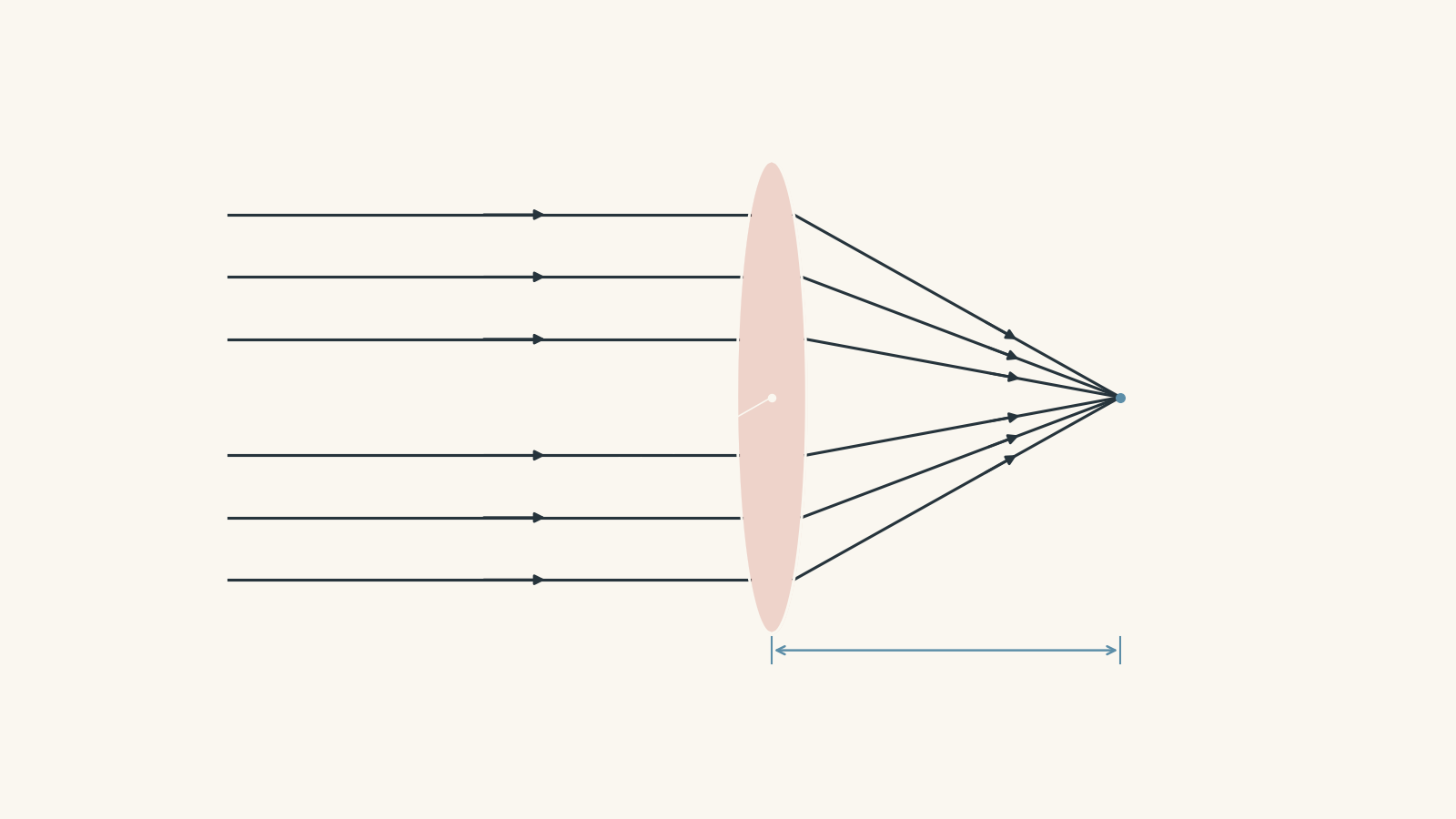
A diverging lens, which is thinner near the middle, does the opposite. Parallel rays spread apart after passing through it. If you extend those refracted rays backwards, they appear to have come from the focal point on the incoming side.
That word appear matters. The rays don’t actually travel backwards through that point.
02Why principal rays are useful
Imagine trying to draw every ray leaving the top of a candle. You’d run out of page, patience, or both.
Instead, we choose a few rays whose paths through a thin lens are especially easy to predict. They’re called principal rays.
Think of them as three known routes through a train station. You don’t need to follow every passenger to work out where two groups meet. You follow a few reliable paths.
The analogy has a limit: real light isn’t restricted to three special rays. An object point sends many rays through many parts of the lens. Principal rays are simply convenient representatives.
For HSC ray diagrams, two correctly drawn principal rays are enough to locate an image. A third ray can be used as a check.
03The three principal rays for a converging lens
Suppose light is travelling from left to right.
Ray 1: parallel to the principal axis
A ray travelling parallel to the principal axis refracts through the focal point on the far side of a converging lens.
So:
parallel in -> through far focus out
Ray 2: through the near focal point
A ray travelling through the focal point on the object’s side of the lens emerges parallel to the principal axis.
So:
through near focus in -> parallel out
Ray 3: through the optical centre
A ray passing through the optical centre of a thin lens continues approximately straight ahead.
This is a thin-lens approximation. A real lens has two curved surfaces, so the ray refracts at both. For the thin lenses used in standard HSC ray diagrams, treating the central ray as undeviated is an excellent model.
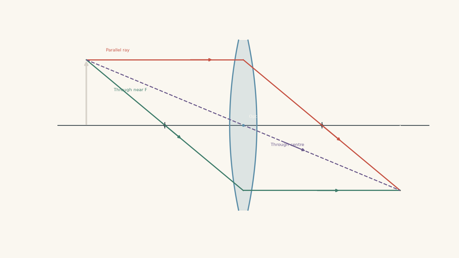
Notice what all three rays have in common: they begin at the same point on the object. Usually, we draw them from the top of an arrow.
Where the refracted rays meet is where the corresponding point of the image forms.
04Reading an image from a ray diagram
Once you’ve located the image, describe four things:
| Property | Question to ask |
|---|---|
| Position | Where is the image relative to the lens and focal points? |
| Orientation | Is it upright or inverted? |
| Size | Is it enlarged, diminished, or the same size? |
| Type | Is it real or virtual? |
The distinction between real and virtual images causes the most trouble.
A real image forms where actual light rays meet. Because light physically passes through the image position, the image can be projected onto a screen.
A virtual image forms where rays only appear to originate. The actual rays do not meet at the image position, so placing a screen there will not capture the image.
A mirror image of your face is a familiar example. Your face seems to be behind the mirror, but there are no light rays from your face actually travelling around behind it.
05What happens as an object moves towards a converging lens?
This is the key pattern.
Predict first: if an object moves closer and closer to a converging lens, do you expect its image simply to move closer as well?
It doesn’t.
The behaviour changes dramatically when the object crosses the focal point.
Object beyond \(2F\)
The image forms between \(F\) and \(2F\) on the opposite side.
It is:
- real
- inverted
- diminished
Object at \(2F\)
The image forms at \(2F\) on the opposite side.
It is:
- real
- inverted
- the same size as the object
Object between \(F\) and \(2F\)
The image forms beyond \(2F\) on the opposite side.
It is:
- real
- inverted
- enlarged
Object at \(F\)
The rays leaving the lens are parallel.
They do not meet at any finite distance, so we say the image is at infinity.
This is an important limiting case. Don’t mechanically write “real and inverted” just because the object isn’t inside \(F\). At exactly \(F\), there is no finite image position.
Object inside \(F\)
Now something different happens. The refracted rays spread apart rather than meeting on the far side.
Extend them backwards. Their extensions meet on the same side of the lens as the object.
The image is:
- virtual
- upright
- enlarged
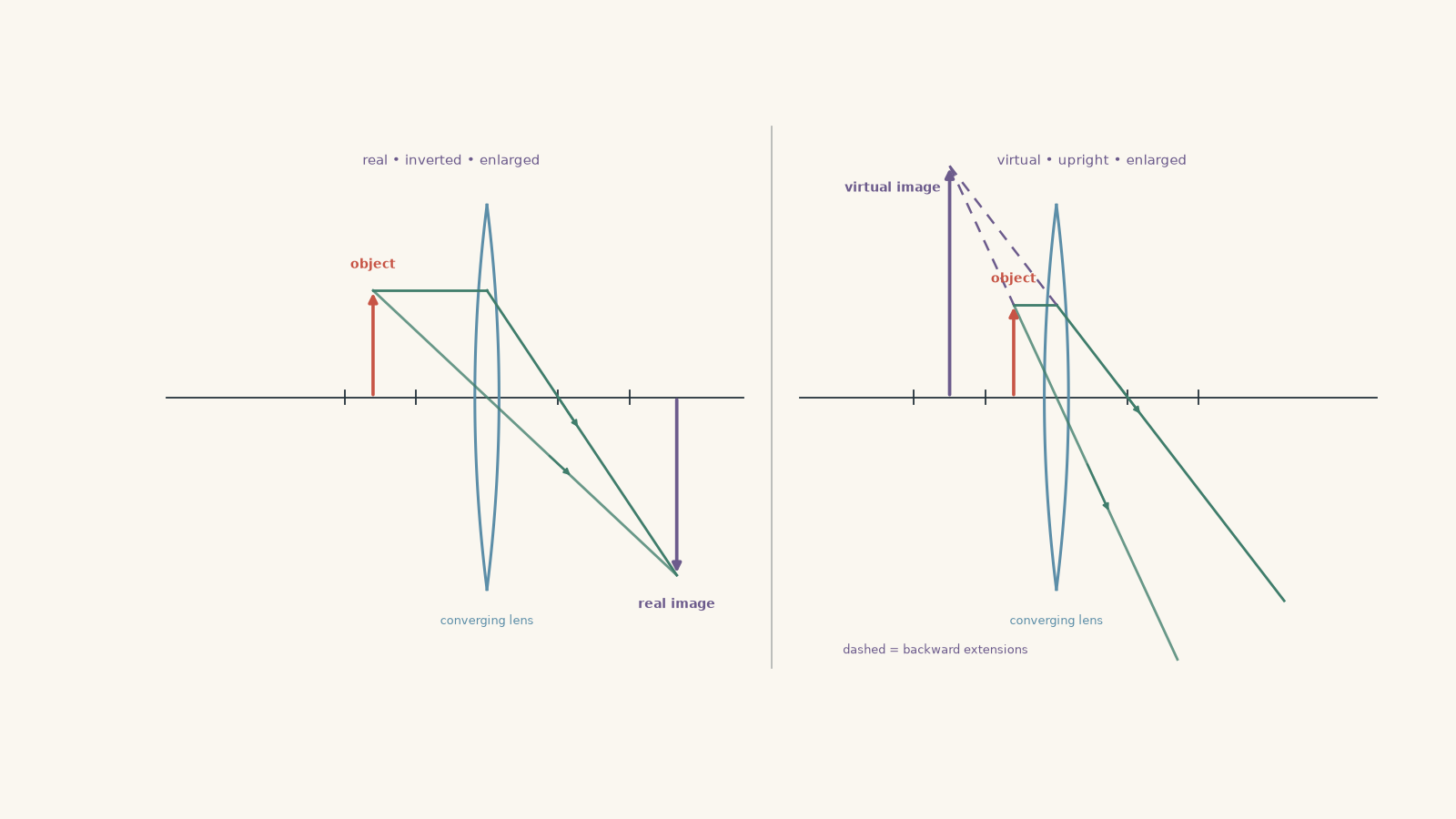
This is how a magnifying glass works. The object is held closer to the lens than its focal length.
06A compact converging-lens pattern
| Object position | Image position | Orientation | Size | Type |
|---|---|---|---|---|
| Beyond \(2F\) | Between \(F\) and \(2F\) | Inverted | Diminished | Real |
| At \(2F\) | At \(2F\) | Inverted | Same size | Real |
| Between \(F\) and \(2F\) | Beyond \(2F\) | Inverted | Enlarged | Real |
| At \(F\) | At infinity | Not a finite image | – | – |
| Inside \(F\) | Same side as object | Upright | Enlarged | Virtual |
You can memorise this table, but you’ll be much safer if you can rebuild it from principal rays.
07Connecting the ray diagram to the lens equation
A ray diagram tells you roughly where the image forms. The thin-lens equation gives the position quantitatively:
\[
\frac{1}{f}=\frac{1}{d_o}+\frac{1}{d_i}
\]
where:
- \(f\) is the focal length
- \(d_o\) is the object distance from the lens
- \(d_i\) is the image distance from the lens
Using the common sign convention here:
- a converging lens has \(f>0\)
- a diverging lens has \(f<0\)
- a real object has \(d_o>0\)
- a real image has \(d_i>0\)
- a virtual image has \(d_i<0\)
The magnification is
\[
m=\frac{h_i}{h_o}=-\frac{d_i}{d_o}
\]
where \(h_o\) is the object height and \(h_i\) is the image height.
The sign and magnitude of \(m\) tell you different things:
- \(m<0\): inverted image
- \(m>0\): upright image
- \(|m|>1\): enlarged
- \(|m|<1\): diminished
- \(|m|=1\): same size
The equations aren’t separate from the ray diagram. They are describing the same geometry more precisely.
Worked example: An object beyond twice the focal length
A 4.0 cm tall object is placed 18 cm from a converging lens with focal length 6.0 cm. Find the image position and height, and describe the image.
Before calculating, make a prediction. Since \(2f=12\text{ cm}\), the object is beyond \(2F\). The ray-diagram pattern therefore predicts a real, inverted, diminished image between \(F\) and \(2F\).
Step 1
\[
\frac{1}{f}=\frac{1}{d_o}+\frac{1}{d_i}
\]
Substitute \(f=6.0\text{ cm}\) and \(d_o=18\text{ cm}\):
\[
\frac{1}{6.0}=\frac{1}{18}+\frac{1}{d_i}
\]
\[
\frac{1}{d_i}
=\frac{1}{6.0}-\frac{1}{18}
=\frac{3}{18}-\frac{1}{18}
=\frac{2}{18}
=\frac{1}{9}
\]
So,
\[
d_i=9.0\text{ cm}
\]
The positive image distance means the image is real.
Step 2
\[
m=-\frac{d_i}{d_o}
=-\frac{9.0}{18}
=-0.50
\]
Step 3
\[
m=\frac{h_i}{h_o}
\]
so
\[
h_i=mh_o=(-0.50)(4.0\text{ cm})=-2.0\text{ cm}
\]
The negative height means the image is inverted.
Step 4
The image is 9.0 cm from the lens on the opposite side, so it lies between \(F=6.0\text{ cm}\) and \(2F=12\text{ cm}\). It is real, inverted, and half the object’s height.
That matches the principal-ray prediction.
08The important case: object inside the focal length
Suppose the object is closer to a converging lens than \(F\).
A common mistake is to keep drawing the refracted rays until they meet somewhere on the far side. They won’t.
After the lens, the rays are diverging. To locate the image, extend those rays backwards using dashed lines. The backward extensions meet on the object’s side.
The dashed lines are not actual light paths. They show where the light appears to have come from.
Worked example: A magnifying-glass image
A small object is placed 8.0 cm from a converging lens of focal length 12 cm. The object is 3.0 cm tall. Determine the image position and height, and describe the image.
Here \(d_o<f\), so a ray diagram predicts a virtual, upright, enlarged image.
Step 1
\[
\frac{1}{f}=\frac{1}{d_o}+\frac{1}{d_i}
\]
Substitute \(f=12\text{ cm}\) and \(d_o=8.0\text{ cm}\):
\[
\frac{1}{12}
=\frac{1}{8.0}+\frac{1}{d_i}
\]
\[
\frac{1}{d_i}
=\frac{1}{12}-\frac{1}{8}
=\frac{2}{24}-\frac{3}{24}
=-\frac{1}{24}
\]
Therefore,
\[
d_i=-24\text{ cm}
\]
The negative sign tells us the image is virtual and lies on the same side of the lens as the object.
Step 2
\[
m=-\frac{d_i}{d_o}
=-\frac{-24}{8.0}
=3.0
\]
The positive magnification means the image is upright.
Step 3
\[
h_i=mh_o=(3.0)(3.0\text{ cm})=9.0\text{ cm}
\]
Step 4
The virtual image appears 24 cm from the lens on the object’s side. It is upright and three times the object’s height.
The negative \(d_i\) isn’t a mathematical annoyance. It contains physical information: the rays themselves never reach that image position.
09Principal rays for a diverging lens
A diverging lens uses the same basic idea, but the first two principal rays change.
Ray 1: parallel to the axis
A ray parallel to the principal axis refracts away from the axis as though it came from the focal point on the near side of the lens.
You need to extend the refracted ray backwards to that focal point.
Ray 2: aimed towards the far focal point
A ray directed towards the focal point on the far side emerges parallel to the principal axis.
Ray 3: through the optical centre
A ray through the optical centre continues approximately straight.
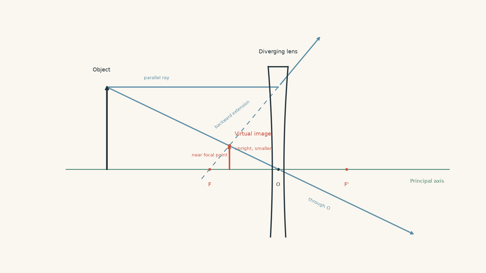
For an ordinary real object, a diverging lens always produces an image that is:
- virtual
- upright
- diminished
- between the lens and the near focal point
The object distance can change, but those four broad features remain.
10Why a diverging lens cannot form a real image of an ordinary object by itself
Think about what would have to happen for a real image to form: actual rays would need to converge and cross after the lens.
But a diverging lens takes the rays arriving from a real object and makes them spread apart more strongly. They therefore cannot meet on the outgoing side.
Their backward extensions can meet, which gives a virtual image.
This statement assumes the lens is receiving light from an ordinary real object. In more advanced optical systems, the incoming rays may already be converging because of another lens or mirror. Then a diverging lens can behave differently. That’s one reason sign conventions and ray directions matter more than memorised slogans.
11The most tempting mistakes
Mistake 1: “An upright image must be real”
It’s usually the opposite in the simple single-lens cases studied here.
For a converging lens with the object inside \(F\), the image is upright because it is virtual. For a diverging lens with a real object, the image is also upright and virtual.
Mistake 2: “The image is wherever the rays seem closest”
No. For a real image, the actual refracted rays must intersect.
For a virtual image, the backward extensions of the refracted rays must intersect.
Draw them properly. Eyeballing the diagram is risky.
Mistake 3: “Principal rays are the only rays forming the image”
They aren’t.
Every point on an illuminated object sends many rays towards the lens. Principal rays are just the easiest rays to construct accurately.
This becomes important if part of a lens is covered. The whole image can still form because light from each object point normally passes through many different parts of the lens. The image becomes dimmer because less light reaches it.
Mistake 4: “The image flips when the object passes through \(2F\)”
The important boundary is \(F\), not \(2F\).
At \(2F\), the image simply changes from diminished to enlarged as the object continues inward. It remains real and inverted on both sides of \(2F\).
Crossing \(F\) is the dramatic change. Outside \(F\), a converging lens can form a finite real image. Inside \(F\), it forms a virtual, upright image.
12A reliable method for any HSC lens diagram
When you see a lens-image question, don’t start by trying to remember a whole table.
Use this sequence:
- Identify whether the lens is converging or diverging.
- Draw the principal axis and mark \(F\), and \(2F\) if useful.
- Draw the object at its stated position.
- From the top of the object, draw two principal rays accurately.
- If the refracted rays meet, their intersection gives a real image.
- If they diverge, extend them backwards with dashed lines. Their backward intersection gives a virtual image.
- Draw the image from the axis to the intersection point.
- Describe its position, orientation, size, and type.
- If numerical values are given, use the thin-lens and magnification equations to confirm the diagram.
The diagram gives you the physics first. The equation then sharpens the answer.
13Questions and solutions
Question 1
An object is placed between \(F\) and \(2F\) of a converging lens.
Without calculation, state where the image forms and describe its orientation, relative size, and type.
Solution 1
The image forms beyond \(2F\) on the opposite side of the lens, and it is inverted, enlarged, and real.
A ray parallel to the axis refracts through the far focal point, while a ray through the optical centre continues approximately straight. Because these actual refracted rays intersect on the far side, the image is real.
For an object between \(F\) and \(2F\), that intersection occurs beyond \(2F\). The image arrow extends below the principal axis, so it is inverted, and its height is greater than the object’s height.
A common trap is to associate “closer object” with “closer image”. In this region, moving the object towards \(F\) actually pushes the real image farther away.
Question 2
A converging lens has focal length \(10.0\text{ cm}\). An object is placed \(30.0\text{ cm}\) from the lens and has a height of \(6.0\text{ cm}\).
Calculate the image distance and image height. Describe the image.
Solution 2
The image forms 15.0 cm from the lens on the opposite side, with height \(-3.0\text{ cm}\), so it is real, inverted, and diminished.
Use
\[
\frac{1}{f}=\frac{1}{d_o}+\frac{1}{d_i}
\]
with \(f=10.0\text{ cm}\) and \(d_o=30.0\text{ cm}\):
\[
\frac{1}{10.0}
=\frac{1}{30.0}+\frac{1}{d_i}
\]
\[
\frac{1}{d_i}
=\frac{1}{10.0}-\frac{1}{30.0}
=\frac{3-1}{30.0}
=\frac{2}{30.0}
\]
so
\[
d_i=15.0\text{ cm}
\]
Since \(d_i\) is positive, the image is real.
The magnification is
\[
m=-\frac{d_i}{d_o}
=-\frac{15.0}{30.0}
=-0.500
\]
Then
\[
h_i=mh_o=(-0.500)(6.0\text{ cm})=-3.0\text{ cm}
\]
The negative height represents an inverted image. Its magnitude is smaller than the object’s height, so the image is diminished.
The result also agrees with the ray-diagram pattern: the object is beyond \(2F=20.0\text{ cm}\), so the image should lie between \(F\) and \(2F\).
Question 3
A diverging lens has focal length \(-12\text{ cm}\). An object is placed \(24\text{ cm}\) in front of the lens.
Calculate the image distance and magnification. Use the signs of your answers to explain the image’s type and orientation.
Solution 3
The image is 8.0 cm from the lens on the object’s side, with magnification \(+0.333\), so it is virtual, upright, and diminished.
Use the thin-lens equation:
\[
\frac{1}{f}=\frac{1}{d_o}+\frac{1}{d_i}
\]
Substitute \(f=-12\text{ cm}\) and \(d_o=24\text{ cm}\):
\[
\frac{1}{-12}
=\frac{1}{24}+\frac{1}{d_i}
\]
\[
\frac{1}{d_i}
=-\frac{1}{12}-\frac{1}{24}
=-\frac{2}{24}-\frac{1}{24}
=-\frac{3}{24}
=-\frac{1}{8}
\]
Therefore,
\[
d_i=-8.0\text{ cm}
\]
The negative image distance means the image is virtual and lies on the same side as the object.
Now calculate magnification:
\[
m=-\frac{d_i}{d_o}
=-\frac{-8.0}{24}
=+0.333
\]
The positive sign means the image is upright. Since \(|m|<1\), it is diminished.
The result also fits the principal-ray picture for a diverging lens: the virtual image lies between the lens and its near focal point.
Question 4
A student places an object exactly at the focal point of a converging lens. They say:
“The image must form at \(2F\), because \(2F\) is the next labelled position on the ray diagram.”
Explain what actually happens. Support your answer using both principal rays and the thin-lens equation.
Solution 4
The image is not at \(2F\). For an object exactly at \(F\), the refracted rays are parallel, so there is no image at any finite distance. The image is described as being at infinity.
Using principal rays, take a ray through the optical centre and another ray whose path is chosen using the focal-point rule. When the object is at the focal point, the relevant refracted rays emerge parallel rather than converging.
Parallel rays do not intersect at a finite point.
The equation gives the same result. If
\[
d_o=f
\]
then
\[
\frac{1}{f}
=\frac{1}{f}+\frac{1}{d_i}
\]
Subtracting \(1/f\) from both sides gives
\[
\frac{1}{d_i}=0
\]
which corresponds to
\[
d_i\rightarrow\infty
\]
The student’s mistake is treating \(F\) and \(2F\) as a list of destinations rather than positions that describe different ray geometries.
Question 5
A sharp real image of an illuminated arrow has been formed on a screen using a converging lens. A student covers the upper half of the lens with opaque cardboard.
They predict that the upper half of the image will disappear because rays from the upper half of the object travel through the upper half of the lens.
Is that prediction correct? Explain what will happen to the image and why a simple principal-ray diagram can make this misconception tempting.
Solution 5
The prediction is incorrect. The complete image still forms, but it becomes dimmer.
Each point on the object sends light in many directions. Before the cardboard is added, rays from one point on the arrow can pass through many different regions of the lens and still be refracted towards the corresponding image point.
Covering half the lens removes some of those rays, so less light reaches every part of the image. That lowers the image brightness.
It does not normally remove a matching half of the image.
A basic ray diagram can create the misconception because we usually draw only two or three principal rays from each object point. Those rays are representative construction lines, not the only rays involved in image formation.
This is also a useful reminder of where the principal-ray model is incomplete. Principal rays are excellent for locating and describing an image, but understanding brightness requires remembering that a continuous bundle of rays passes through the lens.
14Where this leads next
Once you can construct lens images with principal rays, equations such as
\[
\frac{1}{f}=\frac{1}{d_o}+\frac{1}{d_i}
\]
stop being isolated formulas. You can predict the sign, rough position, size, and orientation of an image before touching the calculator, then use the mathematics to check the geometry.
That same reasoning becomes useful when several optical components are combined. In cameras, the eye, microscopes, and telescopes, the image produced by one optical element can become the object for the next. The next step is therefore to track successive image formation, rather than treating each lens as if it works alone.