
Combination Circuit Problems: HSC Physics Practice Exam
Test your understanding of combination circuits with this original 40-mark NSW HSC Physics practice paper. Includes timed exam conditions, five progressively challenging questions, complete worked solutions, and a marking guide.
This original tutorgum practice paper is a focused NSW HSC Physics assessment covering combination circuit problems, using the physics-2025 syllabus scope. It tests your ability to reduce mixed series-parallel circuits, calculate equivalent resistance, and reconstruct the currents and potential differences in individual branches.
The paper contains 40 marks across five questions, with difficulty increasing as you work through the assessment. It is an original tutorgum revision resource, not an official, endorsed, past, or predicted NESA examination paper.
01Exam instructions
| Assessment detail | Conditions |
|---|---|
| Total marks | 40 |
| Reading time | 5 minutes |
| Working time | 55 minutes |
| Total suggested time | 60 minutes |
| Permitted equipment | Scientific calculator, pen or pencil, ruler |
| Working | All calculations must show sufficient working |
Assessed content
This paper assesses:
- Reducing combination circuits using series and parallel resistance relationships.
- Calculating total equivalent resistance.
- Applying Ohm’s law to determine total circuit current.
- Reconstructing individual branch currents.
- Calculating potential differences across individual resistors and sections of a circuit.
Assumptions and exclusions
Unless a question states otherwise:
- All batteries and power supplies are ideal.
- Connecting wires have negligible resistance.
- All resistors are ohmic and have constant resistance.
- Circuits operate under steady direct current (DC) conditions.
This is a focused topic assessment, not a full-course Physics examination. Internal resistance, electrical power, alternating current, capacitors, non-ohmic components, and other syllabus modules are excluded.
Use \(R\) for resistance, measured in ohms (\(\Omega\)); \(I\) for current, measured in amperes (A); and \(V\) for potential difference, measured in volts (V).
Show your working, include units, and give non-terminating numerical answers to three significant figures. Keep unrounded values during intermediate calculations.
02Questions
Question 1 (7 marks)
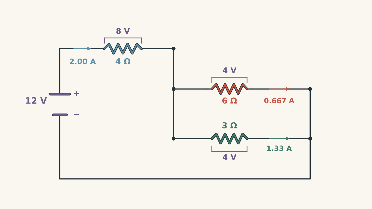
An ideal 12 V battery is connected to a combination circuit containing a 4 \(\Omega\) resistor in series with two parallel resistors of 6 \(\Omega\) and 3 \(\Omega\).
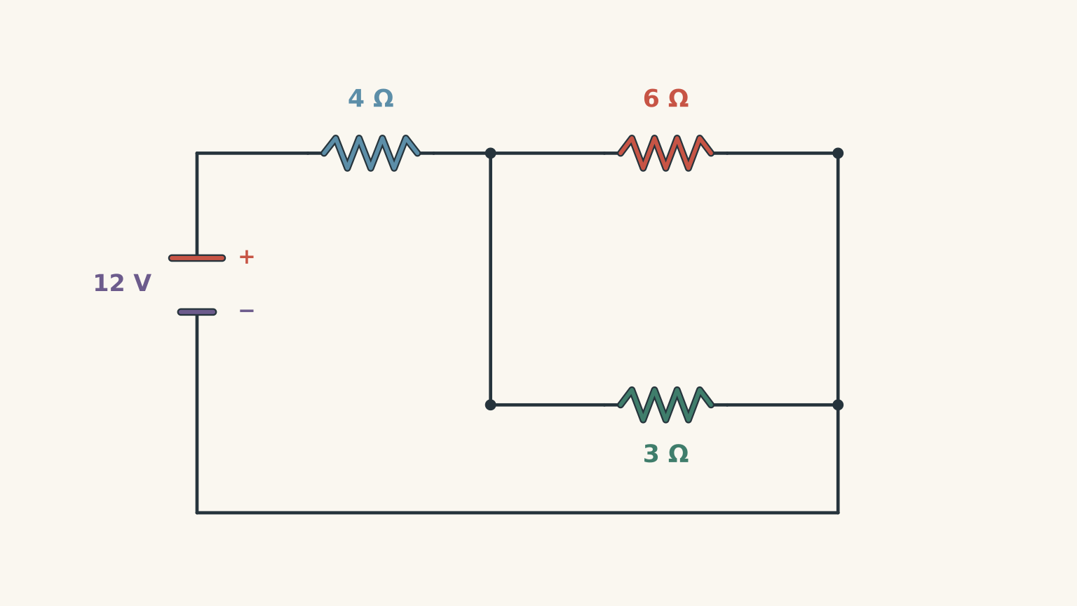
(a) Calculate the equivalent resistance of the parallel section. (2 marks)
(b) Determine the total equivalent resistance of the circuit and the total current supplied by the battery. (2 marks)
(c) Calculate the current flowing through each of the two parallel resistors. (3 marks)
Question 2 (8 marks)
An 18 V ideal power supply is connected to two parallel branches.
The upper branch contains a 3 \(\Omega\) resistor in series with a 6 \(\Omega\) resistor. The lower branch contains a single 6 \(\Omega\) resistor.
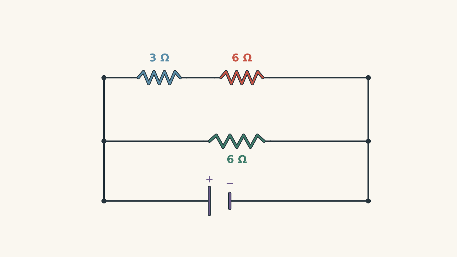
(a) Calculate the equivalent resistance of the upper branch. (1 mark)
(b) Calculate the total equivalent resistance of the circuit. (2 marks)
(c) Determine the total current supplied by the power supply. (1 mark)
(d) Calculate the current flowing through each parallel branch. (2 marks)
(e) Determine the potential difference across each resistor in the upper branch. (2 marks)
Question 3 (8 marks)
A 24 V ideal power supply is connected to a circuit containing two parallel branches.
- The upper branch contains a 4 \(\Omega\) resistor in series with an 8 \(\Omega\) resistor.
- The lower branch contains a 6 \(\Omega\) resistor in series with a 3 \(\Omega\) resistor.
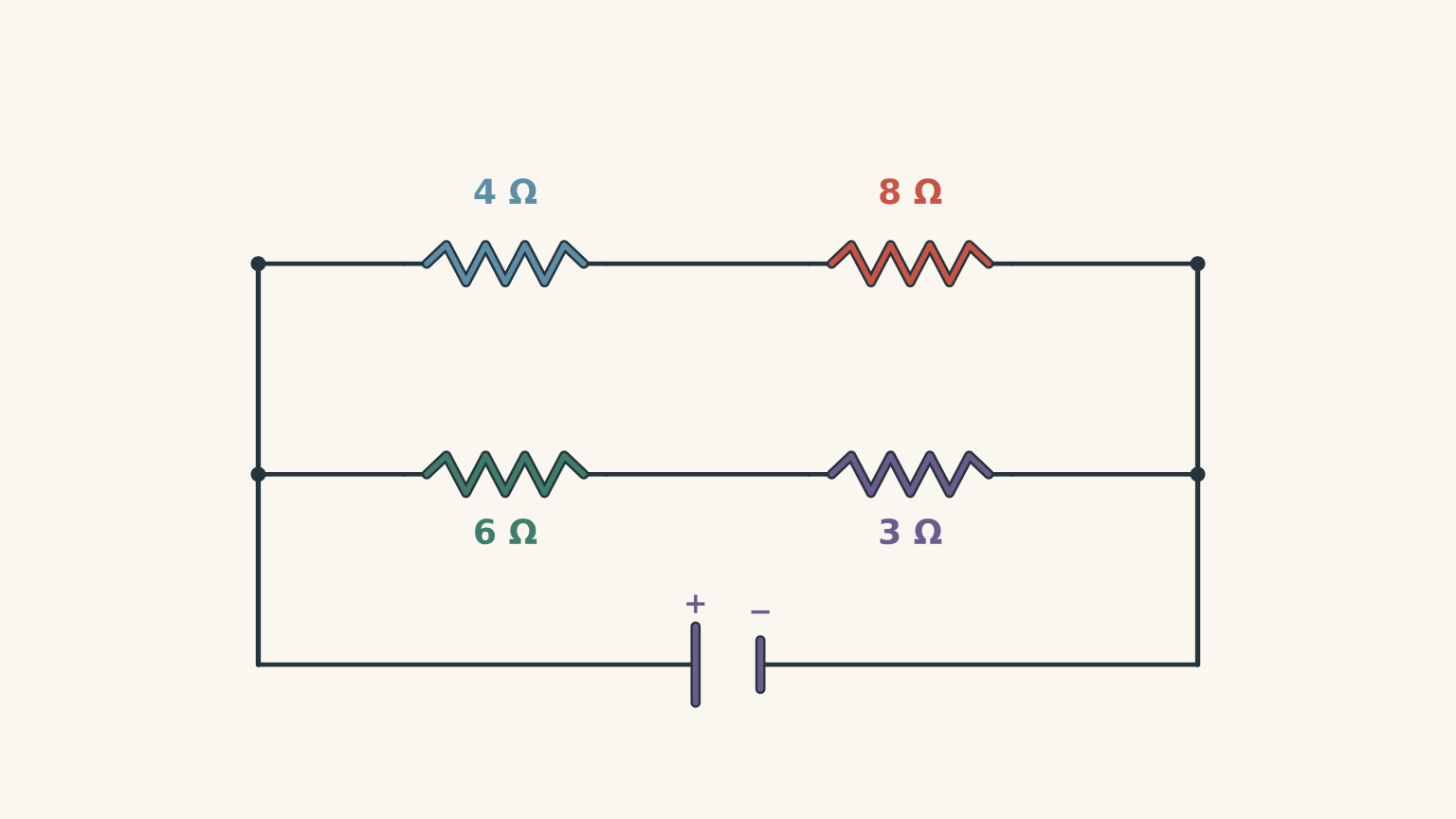
(a) Calculate the equivalent resistance of each parallel branch. (2 marks)
(b) Determine the total equivalent resistance of the circuit. (2 marks)
(c) Calculate the total current supplied by the power supply. (1 mark)
(d) Determine the current flowing through each parallel branch. (2 marks)
(e) Calculate the potential difference across the 8 \(\Omega\) resistor in the upper branch. (1 mark)
Question 4 (9 marks)
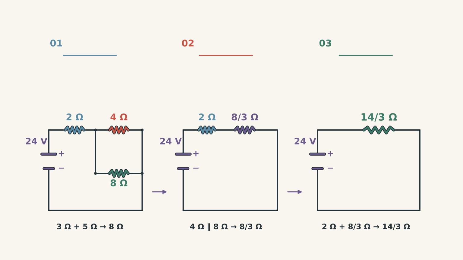
A 24 V ideal power supply is connected to a combination circuit.
A 2 \(\Omega\) resistor is connected in series with a parallel section. The parallel section consists of:
- An upper branch containing a single 4 \(\Omega\) resistor.
- A lower branch containing a 3 \(\Omega\) resistor in series with a 5 \(\Omega\) resistor.
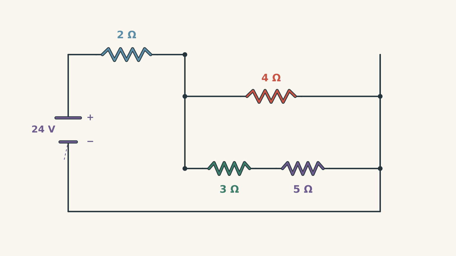
(a) Calculate the equivalent resistance of the lower branch. (1 mark)
(b) Calculate the equivalent resistance of the parallel section. (1 mark)
(c) Determine the total equivalent resistance of the circuit and the total current supplied by the power supply. (2 marks)
(d) Calculate the potential difference across the 2 \(\Omega\) series resistor. (1 mark)
(e) Determine the current flowing through each of the two parallel branches. (2 marks)
(f) Calculate the potential difference across the 3 \(\Omega\) and 5 \(\Omega\) resistors individually. (2 marks)
Question 5 (8 marks)
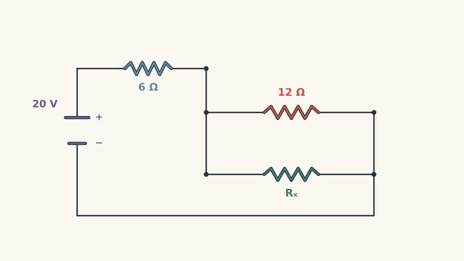
A combination circuit is connected to an ideal 20 V power supply.
A 6 \(\Omega\) resistor is connected in series with a parallel section containing a 12 \(\Omega\) resistor and an unknown resistor, \(R_x\).
The total current supplied by the power supply is measured to be 2.5 A.
(a) Calculate the total equivalent resistance of the circuit. (1 mark)
(b) Determine the equivalent resistance of the parallel section. (1 mark)
(c) Calculate the resistance of the unknown resistor, \(R_x\). (2 marks)
(d) Determine the potential difference across the parallel section. (1 mark)
(e) Calculate the current flowing through the 12 \(\Omega\) resistor and the unknown resistor individually. (2 marks)
(f) Verify that your calculated branch currents are consistent with the measured total current. (1 mark)
03Worked solutions and marking guide
The solutions below show the reduction process and the subsequent reconstruction of individual circuit quantities.
A useful distinction throughout this paper is that equivalent resistance helps you simplify the network, while Ohm’s law helps you recover the quantities in the original circuit.
For marking, equivalent fractions and correctly rounded answers to three significant figures are accepted. Follow-through marks should be awarded where a student makes an earlier numerical error but subsequently applies a correct method consistently.
Solution 1
(a) Equivalent resistance of the parallel section (2 marks)
For resistors connected in parallel, the reciprocal of the equivalent resistance equals the sum of the reciprocals of the individual resistances.
Let \(R_p\) represent the equivalent resistance of the parallel section.
\[ \begin{aligned} \frac{1}{R_p} &=\frac{1}{6}+\frac{1}{3}\\ &=\frac{1}{6}+\frac{2}{6}\\ &=\frac{3}{6}\\ &=\frac{1}{2} \end{aligned} \]
Therefore,
\[ \boxed{R_p=2.0\,\Omega} \]
The equivalent resistance of the parallel section is 2.0 \(\Omega\).
Marking:
- Correct application of the parallel resistance relationship (1 mark).
- Correct equivalent resistance of 2.0 \(\Omega\) (1 mark).
(b) Total equivalent resistance and total current (2 marks)
The 4 \(\Omega\) resistor is connected in series with the parallel section.
For resistors in series, equivalent resistances are added.
\[ \begin{aligned} R_{\text{total}} &=4+2\\ &=6.0\,\Omega \end{aligned} \]
Now apply Ohm’s law to the entire circuit:
\[ V=IR \]
Rearranging for current:
\[ I_{\text{total}}=\frac{V}{R_{\text{total}}} \]
Substituting the supply voltage and total resistance:
\[ I_{\text{total}}=\frac{12}{6} \]
\[ \boxed{I_{\text{total}}=2.0\,\mathrm{A}} \]
The total equivalent resistance is 6.0 \(\Omega\), and the battery supplies 2.0 A.
Marking:
- Correct calculation of total resistance (1 mark).
- Correct application of Ohm’s law and total current (1 mark).
(c) Current through each parallel resistor (3 marks)
Before calculating the individual branch currents, determine the potential difference across the parallel section.
The 4 \(\Omega\) resistor carries the total circuit current of 2 A because it is in series with the entire parallel network.
Using Ohm’s law:
\[ V_{4\Omega}=IR \]
\[ V_{4\Omega}=2\times4=8\,\mathrm{V} \]
The battery supplies 12 V, so the potential difference across the parallel section is:
\[ V_p=12-8 \]
\[ V_p=4\,\mathrm{V} \]
Both parallel resistors have the same potential difference of 4 V.
For the 6 \(\Omega\) resistor:
\[ I_6=\frac{V_p}{R} =\frac{4}{6} \]
\[ \boxed{I_6=0.667\,\mathrm{A}} \]
For the 3 \(\Omega\) resistor:
\[ I_3=\frac{V_p}{R} =\frac{4}{3} \]
\[ \boxed{I_3=1.33\,\mathrm{A}} \]
The current through the 3 \(\Omega\) resistor is greater because it has a lower resistance while experiencing the same potential difference.
We can check the result by adding the branch currents:
\[ I_{\text{total}}=I_6+I_3 \]
\[ 0.667+1.33\approx2.00\,\mathrm{A} \]
This agrees with the total current calculated in part (b).
Marking:
- Correct potential difference across the parallel section (1 mark).
- Correct current through the 6 \(\Omega\) resistor (1 mark).
- Correct current through the 3 \(\Omega\) resistor (1 mark).
Total: 7 marks
Solution 2
(a) Equivalent resistance of the upper branch (1 mark)
The two resistors in the upper branch are connected in series.
Therefore, their equivalent resistance is:
\[ R_{\text{upper}}=3+6 \]
\[ \boxed{R_{\text{upper}}=9\,\Omega} \]
Marking:
- Correct series resistance calculation (1 mark).
(b) Total equivalent resistance (2 marks)
The upper branch has an equivalent resistance of 9 \(\Omega\), while the lower branch has a resistance of 6 \(\Omega\).
These two branches are connected in parallel.
Therefore:
\[ \frac{1}{R_{\text{total}}} =\frac{1}{9}+\frac{1}{6} \]
Using a common denominator:
\[ \begin{aligned} \frac{1}{R_{\text{total}}} &=\frac{2}{18}+\frac{3}{18}\\ &=\frac{5}{18} \end{aligned} \]
Taking the reciprocal:
\[ R_{\text{total}}=\frac{18}{5} \]
\[ \boxed{R_{\text{total}}=3.6\,\Omega} \]
Marking:
- Correct application of the parallel resistance relationship (1 mark).
- Correct total equivalent resistance (1 mark).
(c) Total current supplied by the power supply (1 mark)
Apply Ohm’s law to the entire circuit.
\[ I_{\text{total}}=\frac{V}{R_{\text{total}}} \]
\[ I_{\text{total}}=\frac{18}{3.6} \]
\[ \boxed{I_{\text{total}}=5.0\,\mathrm{A}} \]
Marking:
- Correct application of Ohm’s law and total current (1 mark).
(d) Current through each parallel branch (2 marks)
Both branches are connected directly across the 18 V power supply.
Therefore, each branch experiences a potential difference of 18 V.
For the upper branch:
\[ I_{\text{upper}}=\frac{18}{9} \]
\[ \boxed{I_{\text{upper}}=2.0\,\mathrm{A}} \]
For the lower branch:
\[ I_{\text{lower}}=\frac{18}{6} \]
\[ \boxed{I_{\text{lower}}=3.0\,\mathrm{A}} \]
The lower branch carries more current because its resistance is smaller.
We can verify the result:
\[ I_{\text{total}}=2+3=5\,\mathrm{A} \]
Marking:
- Correct upper branch current (1 mark).
- Correct lower branch current (1 mark).
(e) Potential difference across each resistor in the upper branch (2 marks)
The upper branch has two resistors in series.
The current through both resistors is therefore the same: 2 A.
For the 3 \(\Omega\) resistor:
\[ V_1=IR \]
\[ V_1=2\times3 \]
\[ \boxed{V_1=6.0\,\mathrm{V}} \]
For the 6 \(\Omega\) resistor:
\[ V_2=IR \]
\[ V_2=2\times6 \]
\[ \boxed{V_2=12.0\,\mathrm{V}} \]
The two potential differences add to the total potential difference across the upper branch:
\[ 6+12=18\,\mathrm{V} \]
This confirms the calculation.
Marking:
- Correct potential difference across the 3 \(\Omega\) resistor (1 mark).
- Correct potential difference across the 6 \(\Omega\) resistor (1 mark).
Total: 8 marks
Solution 3
(a) Equivalent resistance of each parallel branch (2 marks)
Start by simplifying the resistors within each branch.
The upper branch contains a 4 \(\Omega\) resistor and an 8 \(\Omega\) resistor in series.
\[ R_A=4+8 \]
\[ \boxed{R_A=12\,\Omega} \]
The lower branch contains a 6 \(\Omega\) resistor and a 3 \(\Omega\) resistor in series.
\[ R_B=6+3 \]
\[ \boxed{R_B=9\,\Omega} \]
Marking:
- Correct equivalent resistance of the upper branch (1 mark).
- Correct equivalent resistance of the lower branch (1 mark).
(b) Total equivalent resistance (2 marks)
The two simplified branches are connected in parallel.
Therefore:
\[ \frac{1}{R_{\text{total}}} =\frac{1}{12}+\frac{1}{9} \]
Using a common denominator:
\[ \begin{aligned} \frac{1}{R_{\text{total}}} &=\frac{3}{36}+\frac{4}{36}\\ &=\frac{7}{36} \end{aligned} \]
Taking the reciprocal:
\[ R_{\text{total}}=\frac{36}{7} \]
\[ \boxed{R_{\text{total}}=5.14\,\Omega} \]
Marking:
- Correct application of the parallel resistance relationship (1 mark).
- Correct total equivalent resistance (1 mark).
(c) Total current supplied by the power supply (1 mark)
Apply Ohm’s law to the complete circuit.
\[ I_{\text{total}}=\frac{V}{R_{\text{total}}} \]
\[ I_{\text{total}}=\frac{24}{36/7} \]
Dividing by a fraction is equivalent to multiplying by its reciprocal:
\[ I_{\text{total}}=\frac{24\times7}{36} \]
\[ \boxed{I_{\text{total}}=4.67\,\mathrm{A}} \]
Marking:
- Correct application of Ohm’s law and total current (1 mark).
(d) Current through each parallel branch (2 marks)
The two branches are connected directly across the power supply.
Each branch therefore has a potential difference of 24 V.
For the upper branch:
\[ I_A=\frac{24}{12} \]
\[ \boxed{I_A=2.0\,\mathrm{A}} \]
For the lower branch:
\[ I_B=\frac{24}{9} \]
\[ \boxed{I_B=2.67\,\mathrm{A}} \]
Notice that the lower branch carries more current because its equivalent resistance is lower.
Check:
\[ I_{\text{total}}=2+\frac{8}{3} \]
\[ I_{\text{total}}=\frac{14}{3} =4.67\,\mathrm{A} \]
This agrees with part (c).
Marking:
- Correct upper branch current (1 mark).
- Correct lower branch current (1 mark).
(e) Potential difference across the 8 \(\Omega\) resistor (1 mark)
The 4 \(\Omega\) and 8 \(\Omega\) resistors are connected in series.
They therefore carry the same current of 2 A.
Using Ohm’s law:
\[ V_8=IR \]
\[ V_8=2\times8 \]
\[ \boxed{V_8=16\,\mathrm{V}} \]
The remaining 8 V is across the 4 \(\Omega\) resistor:
\[ 8+16=24\,\mathrm{V} \]
This matches the supply voltage.
Marking:
- Correct application of Ohm’s law and potential difference of 16 V (1 mark).
Total: 8 marks
Solution 4
This question requires a more careful reduction process because the circuit contains three distinct stages:
- Reduce the two series resistors in the lower branch.
- Combine the two parallel branches.
- Add the remaining series resistor.
Reducing the network in the correct order is essential.
(a) Equivalent resistance of the lower branch (1 mark)
The 3 \(\Omega\) and 5 \(\Omega\) resistors are connected in series.
Therefore:
\[ R_B=3+5 \]
\[ \boxed{R_B=8\,\Omega} \]
Marking:
- Correct series resistance of 8 \(\Omega\) (1 mark).
(b) Equivalent resistance of the parallel section (1 mark)
The parallel section now consists of:
- Upper branch: 4 \(\Omega\).
- Lower branch: 8 \(\Omega\).
Applying the parallel resistance relationship:
\[ \frac{1}{R_p}=\frac{1}{4}+\frac{1}{8} \]
\[ \frac{1}{R_p}=\frac{2}{8}+\frac{1}{8} \]
\[ \frac{1}{R_p}=\frac{3}{8} \]
Therefore:
\[ \boxed{R_p=\frac{8}{3}=2.67\,\Omega} \]
Marking:
- Correct equivalent resistance of the parallel section (1 mark).
(c) Total equivalent resistance and total current (2 marks)
The parallel section is in series with the 2 \(\Omega\) resistor.
Therefore:
\[ R_{\text{total}}=2+\frac{8}{3} \]
\[ R_{\text{total}}=\frac{6}{3}+\frac{8}{3} \]
\[ \boxed{R_{\text{total}}=\frac{14}{3} =4.67\,\Omega} \]
Now calculate the total current using the 24 V supply.
\[ I_{\text{total}}=\frac{V}{R_{\text{total}}} \]
\[ I_{\text{total}}=\frac{24}{14/3} \]
\[ I_{\text{total}}=\frac{24\times3}{14} \]
\[ \boxed{I_{\text{total}}=\frac{36}{7} =5.14\,\mathrm{A}} \]
Marking:
- Correct total equivalent resistance (1 mark).
- Correct total current (1 mark).
(d) Potential difference across the 2 \(\Omega\) resistor (1 mark)
The 2 \(\Omega\) resistor is in series with the parallel section.
It therefore carries the total circuit current of \(36/7\) A.
Applying Ohm’s law:
\[ V_2=IR \]
\[ V_2=\frac{36}{7}\times2 \]
\[ \boxed{V_2=\frac{72}{7} =10.3\,\mathrm{V}} \]
Marking:
- Correct application of Ohm’s law and potential difference (1 mark).
(e) Current through each parallel branch (2 marks)
First, determine the potential difference across the parallel section.
The supply voltage is 24 V, and the 2 \(\Omega\) resistor has a potential difference of \(72/7\) V.
Therefore:
\[ V_p=24-\frac{72}{7} \]
\[ V_p=\frac{168}{7}-\frac{72}{7} \]
\[ V_p=\frac{96}{7} =13.7\,\mathrm{V} \]
Both parallel branches have this same potential difference.
For the upper branch containing the 4 \(\Omega\) resistor:
\[ I_4=\frac{V_p}{4} \]
\[ I_4=\frac{96/7}{4} \]
\[ \boxed{I_4=\frac{24}{7} =3.43\,\mathrm{A}} \]
For the lower branch containing the 3 \(\Omega\) and 5 \(\Omega\) resistors:
\[ I_B=\frac{V_p}{8} \]
\[ I_B=\frac{96/7}{8} \]
\[ \boxed{I_B=\frac{12}{7} =1.71\,\mathrm{A}} \]
The lower branch has a larger equivalent resistance, so it carries less current.
Check:
\[ I_{\text{total}}=\frac{24}{7}+\frac{12}{7} \]
\[ I_{\text{total}}=\frac{36}{7} =5.14\,\mathrm{A} \]
The branch currents correctly add to the total current.
Marking:
- Correct current through the 4 \(\Omega\) branch (1 mark).
- Correct current through the 3 \(\Omega\) and 5 \(\Omega\) branch (1 mark).
(f) Potential difference across the 3 \(\Omega\) and 5 \(\Omega\) resistors (2 marks)
The 3 \(\Omega\) and 5 \(\Omega\) resistors are connected in series.
Therefore, both resistors carry the same branch current:
\[ I_B=\frac{12}{7}\,\mathrm{A} \]
For the 3 \(\Omega\) resistor:
\[ V_3=IR \]
\[ V_3=\frac{12}{7}\times3 \]
\[ \boxed{V_3=\frac{36}{7} =5.14\,\mathrm{V}} \]
For the 5 \(\Omega\) resistor:
\[ V_5=IR \]
\[ V_5=\frac{12}{7}\times5 \]
\[ \boxed{V_5=\frac{60}{7} =8.57\,\mathrm{V}} \]
Check that the two potential differences add to the total potential difference across their branch:
\[ V_3+V_5 =\frac{36}{7}+\frac{60}{7} \]
\[ V_3+V_5=\frac{96}{7} =13.7\,\mathrm{V} \]
This matches the potential difference across the parallel section.
Marking:
- Correct potential difference across the 3 \(\Omega\) resistor (1 mark).
- Correct potential difference across the 5 \(\Omega\) resistor (1 mark).
Total: 9 marks
Solution 5
This question works backwards from the total circuit measurements to determine an unknown resistor.
The key is to use the measured supply voltage and total current to find the total equivalent resistance first.
(a) Total equivalent resistance (1 mark)
The power supply provides 20 V, and the total current is 2.5 A.
Using Ohm’s law:
\[ R_{\text{total}}=\frac{V}{I_{\text{total}}} \]
\[ R_{\text{total}}=\frac{20}{2.5} \]
\[ \boxed{R_{\text{total}}=8.0\,\Omega} \]
Marking:
- Correct total equivalent resistance (1 mark).
(b) Equivalent resistance of the parallel section (1 mark)
The 6 \(\Omega\) resistor is in series with the parallel section.
Therefore:
\[ R_{\text{total}}=R_1+R_p \]
Rearranging:
\[ R_p=R_{\text{total}}-R_1 \]
Substituting:
\[ R_p=8-6 \]
\[ \boxed{R_p=2.0\,\Omega} \]
Marking:
- Correct equivalent resistance of the parallel section (1 mark).
(c) Resistance of the unknown resistor (2 marks)
The parallel section contains a 12 \(\Omega\) resistor and an unknown resistor \(R_x\).
Apply the parallel resistance relationship:
\[ \frac{1}{R_p}=\frac{1}{12}+\frac{1}{R_x} \]
Substitute the known equivalent resistance:
\[ \frac{1}{2}=\frac{1}{12}+\frac{1}{R_x} \]
Rearrange to isolate the unknown term:
\[ \frac{1}{R_x} =\frac{1}{2}-\frac{1}{12} \]
Using a common denominator:
\[ \frac{1}{R_x} =\frac{6}{12}-\frac{1}{12} \]
\[ \frac{1}{R_x}=\frac{5}{12} \]
Take the reciprocal:
\[ \boxed{R_x=\frac{12}{5}=2.4\,\Omega} \]
The unknown resistor has a resistance of 2.4 \(\Omega\).
Marking:
- Correct application and rearrangement of the parallel resistance relationship (1 mark).
- Correct unknown resistance of 2.4 \(\Omega\) (1 mark).
(d) Potential difference across the parallel section (1 mark)
The 6 \(\Omega\) resistor is in series with the parallel section.
It therefore carries the total current of 2.5 A.
Calculate its potential difference:
\[ V_6=IR \]
\[ V_6=2.5\times6 \]
\[ V_6=15\,\mathrm{V} \]
The supply voltage is 20 V.
Therefore, the potential difference across the parallel section is:
\[ V_p=20-15 \]
\[ \boxed{V_p=5.0\,\mathrm{V}} \]
Marking:
- Correct potential difference across the parallel section (1 mark).
(e) Current through each parallel resistor (2 marks)
Both parallel resistors have a potential difference of 5 V.
For the 12 \(\Omega\) resistor:
\[ I_{12}=\frac{V_p}{R} \]
\[ I_{12}=\frac{5}{12} \]
\[ \boxed{I_{12}=0.417\,\mathrm{A}} \]
For the unknown 2.4 \(\Omega\) resistor:
\[ I_x=\frac{V_p}{R_x} \]
\[ I_x=\frac{5}{2.4} \]
\[ \boxed{I_x=2.08\,\mathrm{A}} \]
Notice that the lower-resistance branch carries substantially more current.
Marking:
- Correct current through the 12 \(\Omega\) resistor (1 mark).
- Correct current through the unknown resistor (1 mark).
(f) Verification of total current (1 mark)
The total current entering the parallel section must equal the sum of the two branch currents.
Therefore:
\[ I_{\text{total}}=I_{12}+I_x \]
Using the unrounded values:
\[ I_{\text{total}}=\frac{5}{12}+\frac{25}{12} \]
\[ I_{\text{total}}=\frac{30}{12} \]
\[ \boxed{I_{\text{total}}=2.50\,\mathrm{A}} \]
This agrees exactly with the measured supply current.
The calculated branch currents are therefore consistent with the given circuit measurements.
Marking:
- Correct verification that the branch currents add to 2.5 A (1 mark).
Total: 8 marks
04Final mark summary
| Question | Main assessed skill | Marks |
|---|---|---|
| 1 | Series resistor combined with a parallel section | 7 |
| 2 | Parallel branches containing different resistor arrangements | 8 |
| 3 | Reduction and reconstruction of two series branches | 8 |
| 4 | Multi-stage combination circuit reduction | 9 |
| 5 | Finding an unknown resistance from circuit measurements | 8 |
| Total | 40 |
Final self-check
After completing the paper, check that you can consistently apply these circuit relationships:
- Series resistors: equivalent resistance is the sum of individual resistances.
- Parallel resistors: the reciprocals of individual resistances add.
- Series components carry the same current.
- Parallel branches have the same potential difference.
- The total current entering a parallel section equals the sum of its branch currents.
- Ohm’s law connects resistance, current, and potential difference.
Most importantly, reduce a combination circuit in the correct order before trying to calculate individual branch quantities. Once you have the equivalent circuit, work backwards through the original network to recover the currents and potential differences.
End of paper – 40 marks