
Electric Motors and Back EMF: HSC Physics Practice Exam
Test your understanding of electric motors and back emf with this original 45-mark tutorgum HSC Physics practice paper. Includes timed exam conditions, five questions, complete worked solutions, and a detailed marking guide.
This is an original tutorgum practice paper for the HSC Physics 2017 syllabus edition. It assesses electric motors and back emf, including the components and operation of simple DC motors, torque on a current-carrying coil, back emf, and AC induction motors.
This is a focused topic paper, not a full-course exam. It is not an official, endorsed, past, or predicted NESA paper.
01Exam instructions
| Assessment detail | Conditions |
|---|---|
| Suggested reading time | 5 minutes |
| Working time | 60 minutes |
| Total marks | 45 |
| Questions | 5 compulsory questions |
| Equipment | Scientific calculator, ruler, pens, and pencils |
- Answer all questions.
- Show working for all calculations, including substitutions into equations.
- Include appropriate units in numerical answers.
- Give calculated answers to 2 significant figures unless greater precision is appropriate.
- Diagrams are provided where they help establish the physical arrangement. Draw additional diagrams in your answers when they help explain your reasoning.
- Accept the simplified assumptions stated in individual questions.
Assessed syllabus scope
This paper covers the supplied Physics 2017 syllabus scope:
- Components and operation of a simple DC motor.
- The role of the split-ring commutator and brushes.
- Torque on a current-carrying coil using \(\tau=nIAB\sin\theta\).
- The origin of back emf and its effects on current, speed, and energy transfer.
- Rotating magnetic fields and induced rotor currents in AC induction motors.
Other syllabus modules, detailed generator theory, transformer theory, and general AC circuit analysis are excluded.
These assessment conditions are set for this tutorgum practice paper and are not a statement of official NESA examination rules.
02Questions
Question 1 (8 marks)
Figure 1 shows a simple DC motor. Four components have been labelled A, B, C, and D.
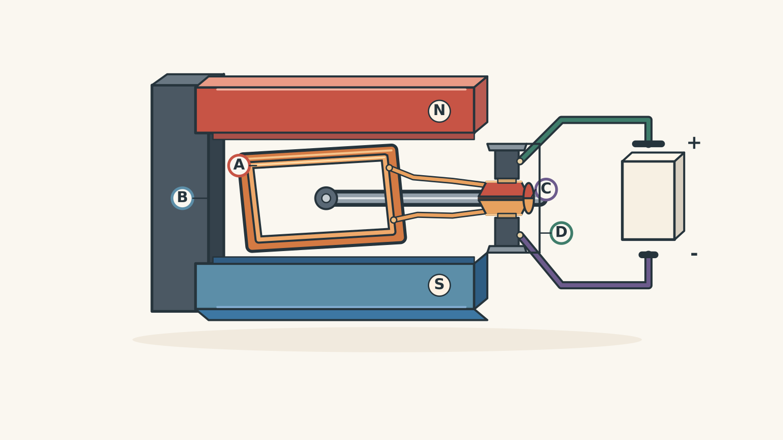
(a) State the function of each labelled component in the operation of the motor. (4 marks)
(b) Explain how the split-ring commutator allows the coil to continue rotating in the same direction after each half-turn. (2 marks)
(c) A student replaces the split-ring commutator with two continuous slip rings but leaves the DC supply and coil unchanged.
Predict what happens to the torque direction after each half-turn, and explain whether the motor will maintain continuous rotation in one direction. (2 marks)
Question 2 (9 marks)
A rectangular coil in an electric motor has the following properties:
- Number of turns: \(n=80\)
- Area of each turn: \(A=3.0\times10^{-3}\,\mathrm{m^2}\)
- Current through the coil: \(I=0.50\,\mathrm{A}\)
- Magnetic flux density: \(B=0.20\,\mathrm{T}\)
The coil is placed in a uniform magnetic field.
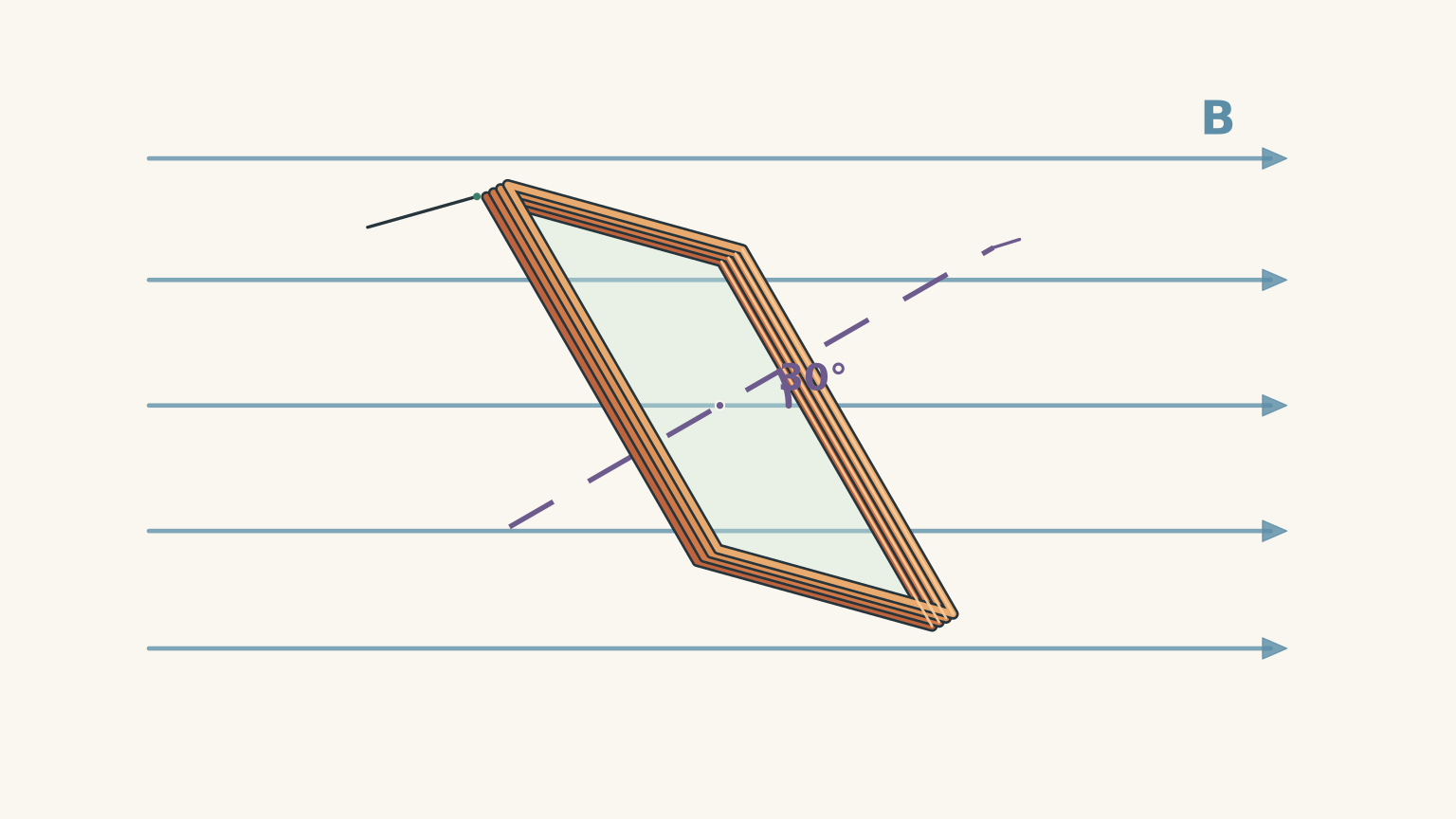
Figure 2 shows the initial orientation of the coil. The angle \(\theta\) is measured between the magnetic field and the normal to the plane of the coil.
The torque on the coil is given by:
\[ \tau=nIAB\sin\theta \]
where:
- \(\tau\) is the torque in newton metres (N m)
- \(n\) is the number of turns
- \(I\) is the current in amperes (A)
- \(A\) is the area of one turn in square metres (m²)
- \(B\) is the magnetic flux density in teslas (T)
- \(\theta\) is the angle between the magnetic field and the coil’s normal.
(a) Calculate the torque acting on the coil at its initial orientation, where \(\theta=30^\circ\). (3 marks)
(b) The coil is rotated until its normal is perpendicular to the magnetic field.
Calculate the torque acting on the coil in this orientation. (2 marks)
(c) The coil is rotated again until its normal is parallel to the magnetic field.
Calculate the torque acting on the coil in this orientation. (2 marks)
(d) The coil is returned to its initial orientation. Its number of turns is then doubled, while all other quantities remain unchanged.
Calculate the new torque acting on the coil. (2 marks)
Question 3 (10 marks)
A simple DC motor, arranged as shown in Figure 1, is connected to a \(12.0\,\mathrm{V}\) DC power supply.
The armature resistance is \(3.0\,\Omega\).
For this simplified motor model, neglect armature inductance and mechanical energy losses. The relationship between supply voltage, back emf, and armature current is:
\[ V=E_b+IR \]
where:
- \(V\) is the supply voltage
- \(E_b\) is the back emf
- \(I\) is the armature current
- \(R\) is the armature resistance.
When the motor is first switched on, its rotor is stationary and its back emf is negligible.
Once the motor reaches a steady operating speed, its back emf is measured to be \(9.0\,\mathrm{V}\).
(a) Calculate the current flowing through the motor immediately after it is switched on. (2 marks)
(b) Calculate the current flowing through the motor at its steady operating speed. (2 marks)
(c) Explain:
- how back emf is produced in a DC motor;
- why its direction opposes the applied supply voltage; and
- how back emf changes as the motor increases in speed.
(3 marks)
(d) At the steady operating speed, calculate:
- the electrical power supplied to the motor;
- the power dissipated as heat in the armature resistance; and
- the rate at which electrical energy is converted into mechanical energy.
(3 marks)
Question 4 (8 marks)
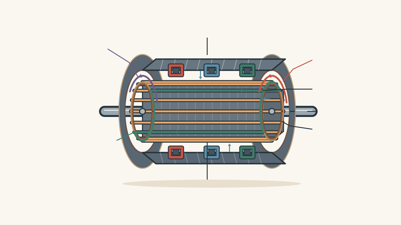
Figure 3 shows a three-phase AC induction motor.
The stationary outer section, called the stator, contains three sets of windings labelled A, B, and C. These windings are arranged at different positions around the motor and connected to a three-phase AC supply.
The central rotor consists of conducting bars connected together at both ends by conducting rings. It has no direct electrical connection to the power supply.
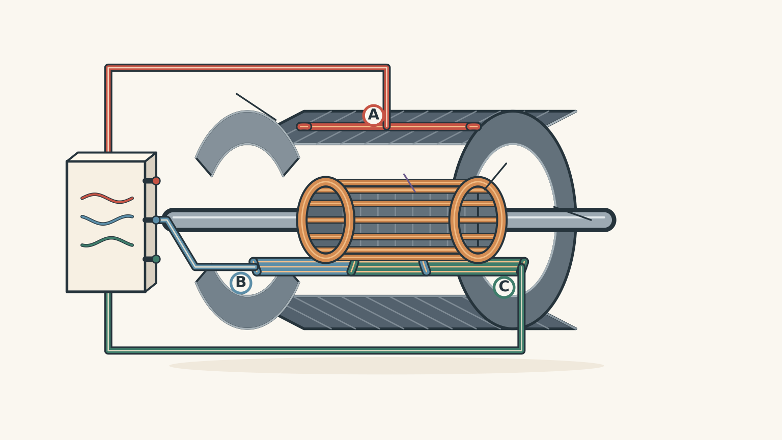
(a) Explain how the AC currents flowing through the stator windings produce a rotating magnetic field. (3 marks)
(b) Explain how currents are induced in the rotor, and how these currents produce a torque that causes the rotor to turn. (3 marks)
(c) Explain why the rotor must rotate slightly slower than the rotating magnetic field during normal operation. (2 marks)
Question 5 (10 marks)
Consider the two motor arrangements shown in Figures 1 and 3.
Motor X is a simple DC motor consisting of a coil between permanent magnets, connected to a DC supply through brushes and a split-ring commutator.
Motor Y is a three-phase AC induction motor consisting of stator windings surrounding a conducting cage rotor.
(a) For each motor, describe how electrical current is established in its rotor conductors.
(4 marks)
(b) Explain how each motor arrangement produces torque that sustains rotation.
Your answer should refer to the relevant magnetic fields and the role of the motor’s components. (4 marks)
(c) A student makes the following statement:
“The rotating magnetic field in an induction motor is essentially a split-ring commutator without moving contacts. They perform the same function.”
Evaluate this statement. (2 marks)
03Worked solutions and marking guide
Solution 1
(a) Functions of the four components (4 marks)
A: Coil
The coil carries an electric current. Its interaction with the magnetic field produces forces on its sides, generating a torque that makes the coil rotate.
B: Permanent magnets
The magnets provide the magnetic field in which the current-carrying coil is placed.
C: Split-ring commutator
The split-ring commutator reverses the direction of current flowing through the coil every half-turn.
D: Brushes
The brushes are stationary electrical contacts. They maintain an electrical connection between the external DC supply and the rotating split-ring commutator.
Marking guide:
- 1 mark: Correct function of the coil.
- 1 mark: Correct function of the magnets.
- 1 mark: Correct function of the split-ring commutator.
- 1 mark: Correct function of the brushes.
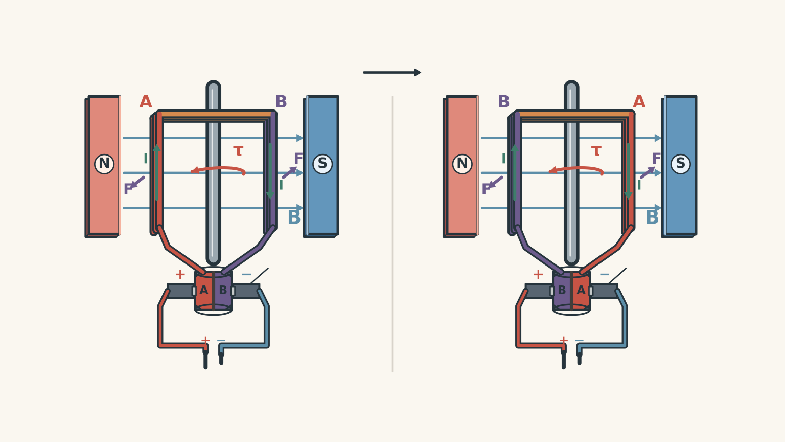
(b) Maintaining rotation in the same direction (2 marks)
As the coil completes half a rotation, its sides exchange positions within the magnetic field.
Without changing the current, the torque would reverse direction. The coil would therefore experience a torque opposing its original rotation.
The split-ring commutator solves this problem by switching the electrical connections every half-turn. This reverses the current flowing through the coil.
The forces on the coil sides consequently change in a way that keeps the torque acting in the same rotational direction.
Marking guide:
- 1 mark: Identifies that the split-ring commutator reverses the coil current after each half-turn.
- 1 mark: Explains that this maintains torque in the same rotational direction.
(c) Replacing the split-ring commutator with continuous slip rings (2 marks)
Continuous slip rings maintain the electrical connection between the DC supply and the rotating coil, but they do not reverse the coil’s current direction.
Consequently, after each half-turn, the torque on the coil reverses direction.
The motor would not maintain continuous rotation in one direction because the torque would alternate between driving and opposing its rotation.
Marking guide:
- 1 mark: Explains that continuous slip rings do not reverse the current in the coil.
- 1 mark: Identifies that torque reverses after each half-turn, preventing sustained rotation in one direction.
Solution 2
(a) Torque at an angle of \(30^\circ\) (3 marks)
Start with the supplied torque equation:
\[ \tau=nIAB\sin\theta \]
Substitute the given values:
\[ \begin{aligned} \tau &=80(0.50)(3.0\times10^{-3})\\ &\quad\times0.20\sin30^\circ \end{aligned} \]
Since \(\sin30^\circ=0.5\):
\[ \begin{aligned} \tau &=80(0.50)(3.0\times10^{-3})\\ &\quad\times0.20(0.5)\\ &=1.2\times10^{-2}\,\mathrm{N\,m} \end{aligned} \]
Therefore, the torque is:
\[ \boxed{\tau=0.012\,\mathrm{N\,m}} \]
Marking guide:
- 1 mark: Correct substitution into the torque equation.
- 1 mark: Correct numerical calculation.
- 1 mark: Correct unit.
(b) Normal perpendicular to the magnetic field (2 marks)
When the normal is perpendicular to the magnetic field:
\[ \theta=90^\circ \]
Substitute into the torque equation:
\[ \begin{aligned} \tau &=80(0.50)(3.0\times10^{-3})\\ &\quad\times0.20\sin90^\circ\\ &=2.4\times10^{-2}\,\mathrm{N\,m} \end{aligned} \]
Therefore:
\[ \boxed{\tau=0.024\,\mathrm{N\,m}} \]
This is the maximum torque because \(\sin90^\circ=1\).
Marking guide:
- 1 mark: Correct angle and use of \(\sin90^\circ=1\).
- 1 mark: Correct torque with units.
(c) Normal parallel to the magnetic field (2 marks)
When the normal is parallel to the magnetic field:
\[ \theta=0^\circ \]
Therefore:
\[ \begin{aligned} \tau &=nIAB\sin0^\circ\\ &=nIAB(0)\\ &=0 \end{aligned} \]
Thus:
\[ \boxed{\tau=0\,\mathrm{N\,m}} \]
The coil experiences no resultant torque from the magnetic field in this orientation.
Marking guide:
- 1 mark: Correctly identifies \(\theta=0^\circ\) and uses \(\sin0^\circ=0\).
- 1 mark: Correctly concludes that the torque is zero.
(d) Doubling the number of turns (2 marks)
The torque equation is:
\[ \tau=nIAB\sin\theta \]
All quantities except \(n\) remain constant.
Therefore, torque is directly proportional to the number of turns:
\[ \tau\propto n \]
Doubling the number of turns doubles the torque calculated in part (a).
\[ \begin{aligned} \tau_{\mathrm{new}} &=2(0.012)\\ &=0.024\,\mathrm{N\,m} \end{aligned} \]
Therefore:
\[ \boxed{\tau_{\mathrm{new}}=0.024\,\mathrm{N\,m}} \]
Marking guide:
- 1 mark: Identifies the direct proportionality between torque and number of turns.
- 1 mark: Correctly calculates the new torque with units.
Solution 3
(a) Current immediately after switching on (2 marks)
The motor is initially stationary.
Since the coil is not rotating, no back emf is produced in the simplified model:
\[ E_b=0 \]
Start with:
\[ V=E_b+IR \]
Rearrange to make current the subject:
\[ I=\frac{V-E_b}{R} \]
Substitute:
\[ \begin{aligned} I&=\frac{12.0-0}{3.0}\\ &=4.0\,\mathrm{A} \end{aligned} \]
Therefore:
\[ \boxed{I=4.0\,\mathrm{A}} \]
Marking guide:
- 1 mark: Correctly rearranges the voltage equation and identifies zero back emf.
- 1 mark: Correct current with units.
(b) Current at steady operating speed (2 marks)
Once the motor reaches steady operating speed, the back emf is \(9.0\,\mathrm{V}\).
Again:
\[ I=\frac{V-E_b}{R} \]
Substitute the values:
\[ \begin{aligned} I&=\frac{12.0-9.0}{3.0}\\ &=\frac{3.0}{3.0}\\ &=1.0\,\mathrm{A} \end{aligned} \]
Therefore:
\[ \boxed{I=1.0\,\mathrm{A}} \]
Notice that the current has decreased from \(4.0\,\mathrm{A}\) to \(1.0\,\mathrm{A}\) as the motor accelerated.
Marking guide:
- 1 mark: Correct substitution into the motor voltage equation.
- 1 mark: Correct current with units.
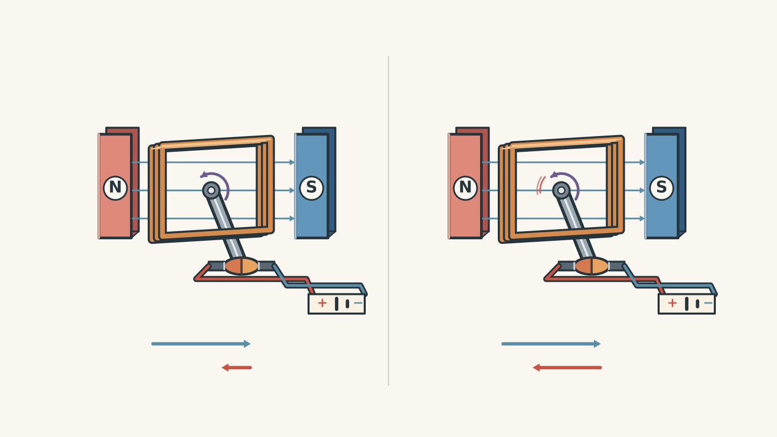
(c) Origin and effects of back emf (3 marks)
Back emf is an induced voltage produced as the motor’s coil rotates through the magnetic field.
The rotating coil experiences a changing magnetic flux, which induces an emf through electromagnetic induction. This is the generator effect.
According to Lenz’s law, the induced emf acts in a direction that opposes the change producing it. In a DC motor, this means the back emf opposes the applied supply voltage.
As the motor speeds up, the coil cuts through the magnetic field more rapidly. The rate of change of magnetic flux increases, so the magnitude of the back emf increases.
This has an important consequence for the motor’s current:
\[ I=\frac{V-E_b}{R} \]
As \(E_b\) increases, the effective voltage across the armature resistance decreases. Therefore, the current decreases.
The motor initially draws a relatively large current to accelerate from rest. As its speed increases, back emf limits the current.
Marking guide:
- 1 mark: Explains that rotation in a magnetic field produces an induced emf through changing magnetic flux.
- 1 mark: Explains that the induced emf opposes the applied voltage, referring to Lenz’s law.
- 1 mark: Explains that increasing rotational speed increases back emf and reduces armature current.
(d) Energy transfers at steady operating speed (3 marks)
From part (b), the steady current is:
\[ I=1.0\,\mathrm{A} \]
The supply voltage is:
\[ V=12.0\,\mathrm{V} \]
The back emf is:
\[ E_b=9.0\,\mathrm{V} \]
First, calculate the electrical input power.
Electrical power is:
\[ P_{\mathrm{in}}=VI \]
Substitute:
\[ P_{\mathrm{in}}=12.0(1.0) \]
\[ \boxed{P_{\mathrm{in}}=12\,\mathrm{W}} \]
Next, calculate the power dissipated as heat in the armature resistance.
\[ P_{\mathrm{heat}}=I^2R \]
Substitute:
\[ P_{\mathrm{heat}}=(1.0)^2(3.0) \]
\[ \boxed{P_{\mathrm{heat}}=3.0\,\mathrm{W}} \]
Finally, calculate the rate of electrical energy conversion into mechanical energy.
For an idealised motor, the electromechanical conversion power is:
\[ P_{\mathrm{mech}}=E_bI \]
Substitute:
\[ P_{\mathrm{mech}}=9.0(1.0) \]
\[ \boxed{P_{\mathrm{mech}}=9.0\,\mathrm{W}} \]
The energy balance is therefore:
\[ P_{\mathrm{in}} = P_{\mathrm{heat}}+P_{\mathrm{mech}} \]
\[ 12=3+9 \]
The electrical input power is divided between heating in the armature and conversion into mechanical energy.
Marking guide:
- 1 mark: Correct electrical input power, \(12\,\mathrm{W}\).
- 1 mark: Correct resistive heating power, \(3.0\,\mathrm{W}\).
- 1 mark: Correct mechanical energy conversion rate, \(9.0\,\mathrm{W}\), with a consistent energy balance.
Solution 4
(a) Production of a rotating magnetic field (3 marks)
An AC induction motor uses several stator windings arranged at different positions around the motor.
In this question, the three stator winding groups are supplied with three-phase AC.
The currents in these windings vary continuously and are out of phase with one another. Each winding therefore produces a magnetic field that changes with time.
Because the windings are also positioned at different locations around the stator, their individual magnetic fields combine to form a resultant magnetic field that rotates around the stator.
This is called a rotating magnetic field.
The important distinction is that the magnetic field rotates even though the stator windings themselves remain stationary.
Marking guide:
- 1 mark: Identifies the spatially separated stator windings and phase-shifted AC currents.
- 1 mark: Explains that the alternating currents produce changing magnetic fields.
- 1 mark: Explains that the combined magnetic field rotates around the stator.
(b) Induced rotor currents and torque (3 marks)
The rotating magnetic field passes the conducting bars of the rotor.
Because there is relative motion between the rotating magnetic field and the rotor conductors, the magnetic flux through the rotor conductors changes.
This induces an emf in the rotor bars.
The conducting bars are connected by end rings, forming closed electrical paths. The induced emf therefore causes currents to flow through the rotor.
These induced currents produce their own magnetic field. The interaction between the rotor’s magnetic field and the stator’s rotating magnetic field produces a torque on the rotor.
The rotor consequently begins rotating in the direction of the rotating magnetic field.
Marking guide:
- 1 mark: Explains that relative motion between the rotating magnetic field and rotor conductors produces a changing magnetic flux and induced emf.
- 1 mark: Explains that the induced emf drives currents through the closed rotor conductors.
- 1 mark: Explains that the interaction between the rotor currents and stator magnetic field produces torque.
(c) Why the rotor must rotate slower than the rotating magnetic field (2 marks)
The rotor must maintain some relative motion with respect to the rotating magnetic field.
If the rotor reached exactly the same rotational speed as the magnetic field, there would be no relative motion between them.
Consequently, the magnetic flux through the rotor conductors would no longer change due to their relative motion. No sustained rotor emf or induced current would be produced.
Without induced rotor currents, there would be no electromagnetic torque to maintain the motor’s rotation.
Therefore, the rotor must rotate slightly slower than the rotating magnetic field during normal operation.
Marking guide:
- 1 mark: Identifies that equal rotational speeds eliminate relative motion and therefore induction in the rotor.
- 1 mark: Explains that without induced currents, no sustained torque is produced, so the rotor must lag behind the field.
Solution 5
(a) How current is established in each motor (4 marks)
Motor X: Simple DC motor
The rotor coil is connected directly to the DC supply through the brushes and split-ring commutator.
The brushes provide electrical contact with the rotating commutator, allowing current to flow through the coil.
The current is therefore supplied externally.
Motor Y: AC induction motor
The rotor does not have a direct electrical connection to the power supply.
Instead, the rotating magnetic field produced by the stator induces an emf in the conducting rotor bars.
This induced emf drives currents through the closed conducting paths formed by the rotor bars and end rings.
The current is therefore produced through electromagnetic induction rather than supplied through brushes.
Marking guide:
- 1 mark: Identifies that Motor X receives current directly from the DC supply.
- 1 mark: Identifies the brushes and split-ring commutator as the electrical connection to Motor X’s coil.
- 1 mark: Identifies that Motor Y’s rotor currents are induced by the rotating magnetic field.
- 1 mark: Explains that the conducting bars and end rings provide closed paths for the induced currents.
(b) How each motor produces torque (4 marks)
Motor X: Simple DC motor
The current-carrying coil experiences forces when placed in the magnetic field produced by the permanent magnets.
These forces produce a torque that causes the coil to rotate.
After every half-turn, the split-ring commutator reverses the current through the coil. This ensures that the torque continues acting in the same rotational direction.
The commutator is therefore essential for maintaining continuous rotation in this simple DC motor arrangement.
Motor Y: AC induction motor
The AC supply produces a rotating magnetic field in the stator.
This field induces currents in the conducting rotor bars. The interaction between the induced rotor currents and the stator’s rotating magnetic field produces a torque.
The torque drives the rotor in the direction of the rotating magnetic field.
Unlike Motor X, Motor Y does not rely on a split-ring commutator to reverse the current in its rotor conductors.
Marking guide:
Motor X:
- 1 mark: Explains that a current-carrying coil in a magnetic field experiences forces that produce torque.
- 1 mark: Explains that the split-ring commutator reverses the coil current every half-turn to maintain torque in the same rotational direction.
Motor Y:
- 1 mark: Explains that the rotating stator field induces currents in the rotor.
- 1 mark: Explains that the interaction between the induced rotor currents and stator field produces torque.
(c) Evaluating the student’s statement (2 marks)
The student’s statement is incorrect.
Although both arrangements contribute to continuous motor rotation, they do not perform the same physical function.
The split-ring commutator in a DC motor is a mechanical electrical switching device. It reverses the direction of current flowing through the rotating coil every half-turn.
The rotating magnetic field in an induction motor is produced by the AC currents in the stationary stator windings. It induces currents in the rotor through electromagnetic induction.
The two arrangements therefore operate through different mechanisms:
- The split-ring commutator changes the electrical connections to an externally supplied coil.
- The rotating magnetic field induces currents in a rotor that has no direct electrical connection to the supply.
They are not interchangeable components.
Marking guide:
- 1 mark: Correctly distinguishes the commutator as a device that reverses current in the DC motor coil.
- 1 mark: Correctly distinguishes the rotating magnetic field as the mechanism that induces currents in the induction motor rotor.
Total: 45 marks
Marking notes: Award marks for scientifically equivalent explanations, even where students use different wording. For multi-step calculations, award appropriate follow-through marks when a student uses an earlier incorrect numerical result consistently but applies the correct subsequent method. Numerical answers must include appropriate units.