
Back emf in a DC motor: HSC Physics explained
Learn where back emf comes from and how it affects current, speed, torque, and energy transfer in a DC motor. Includes worked examples and challenging HSC-style questions.
A DC motor does something slightly strange. Hold its shaft still and connect it to a supply, and the current can be enormous. Let the motor spin freely, and the current falls – even though the supply voltage has not changed.
Before reading on, predict what must be happening. Has the resistance of the copper wire suddenly increased? Or is the spinning motor producing a voltage of its own?
It is the second one. As the motor rotates, its armature also behaves like a generator. The rotation produces an induced emf that opposes the supply voltage. This is back emf, and it explains why motor current depends so strongly on speed.
01Where does back emf come from?
Start with the motor before it is moving.
A current passes through conductors in a magnetic field. Those conductors experience a magnetic force, producing a torque on the rotor. The rotor begins to turn.
Now something new happens.
The conductors are moving through the magnetic field. Charges inside those conductors experience a magnetic force, so an emf is induced in the armature. In other words, the same device that is acting as a motor is now also doing a little bit of generator behaviour.
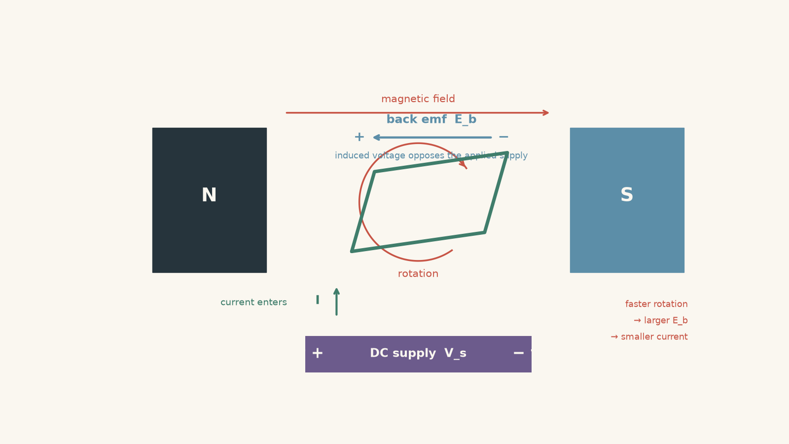
You can picture the electrical side as two people pushing opposite ways on a door. The power supply pushes charges one way. Once the motor is spinning, the induced emf pushes electrically the other way. As the rotor speeds up, that opposing push becomes stronger.
The analogy has a limit. Back emf is not friction, and it is not another physical battery hiding inside the motor. It is a voltage produced by electromagnetic induction.
Connecting this to Faraday’s law
Faraday’s law says that a changing magnetic flux produces an induced emf:
\[ \mathcal{E}=-N\frac{d\Phi}{dt} \]
where:
- \(\mathcal{E}\) is the induced emf in volts,
- \(N\) is the number of turns,
- \(\Phi\) is the magnetic flux through one turn in webers, and
- \(t\) is time in seconds.
As a motor’s armature rotates through the magnetic field, the magnetic flux associated with its coils changes. Faster rotation means the flux changes more rapidly, so the induced emf becomes larger.
The minus sign is Lenz’s law. The induced effect acts in the direction that opposes the change producing it.
For a motor operating normally, that means the induced emf has a polarity that opposes the applied supply voltage. Hence the name back emf.
There is one precision worth adding. A single rotating loop produces an induced emf that varies through each rotation. A practical DC motor contains multiple conductors and uses a commutator, so the brush-to-brush behaviour is much smoother. For a fixed magnetic field, we usually model the motor’s back emf as
\[ \mathcal{E}_b=k_e\omega \]
where:
- \(\mathcal{E}_b\) is the back emf in volts,
- \(\omega\) is the angular speed in radians per second, and
- \(k_e\) is a constant determined by the motor’s construction and magnetic field.
The important relationship is simple:
higher speed \(\rightarrow\) larger back emf.
02How back emf controls the motor current
Suppose the supply provides a voltage \(V_s\). The back emf \(\mathcal{E}_b\) opposes it.
The voltage actually available to drive current through the armature resistance is therefore
\[ V_s-\mathcal{E}_b \]
If the armature resistance is \(R\), Ohm’s law gives
\[ I=\frac{V_s-\mathcal{E}_b}{R} \]
or, equivalently,
\[ V_s=\mathcal{E}_b+IR \]
where \(I\) is the armature current in amperes.
This equation is the key to most HSC back-emf reasoning.
At a fixed supply voltage:
| Motor condition | Speed | Back emf | Current |
|---|---|---|---|
| Stationary | zero | approximately zero | very large |
| Speeding up | increasing | increasing | decreasing |
| Normal steady operation | roughly constant | large but below \(V_s\) | enough to provide required torque |
| Heavier load applied | decreases | decreases | increases |
| Lighter load applied | increases | increases | decreases |
The equation is a simplified DC motor model. It ignores effects such as armature inductance and brush voltage drops. Those effects matter in more detailed motor analysis, but they do not change the basic back-emf mechanism.
Worked example: Why is the starting current so large?
A 24 V DC motor has an armature resistance of \(1.2\,\Omega\). Calculate the current when the motor first starts from rest and when it is running with a back emf of \(18\,\text{V}\).
Step 1
Before the rotor starts turning,
\[ \omega=0 \]
so the motor produces essentially no back emf:
\[ \mathcal{E}_b=0\,\text{V} \]
Step 2
Using
\[ I=\frac{V_s-\mathcal{E}_b}{R} \]
gives
\[ I=\frac{24-0}{1.2}=20\,\text{A} \]
So the starting current is \(20\,\text{A}\).
Step 3
Now \(\mathcal{E}_b=18\,\text{V}\):
\[ I=\frac{24-18}{1.2} =\frac{6}{1.2} =5.0\,\text{A} \]
The running current is \(5.0\,\text{A}\).
Step 4
The resistance did not change. The current fell from \(20\,\text{A}\) to \(5.0\,\text{A}\) because the spinning motor developed an \(18\,\text{V}\) back emf, leaving only \(6\,\text{V}\) across the armature resistance.
This is why a motor can draw a much larger current while starting or stalled than while running normally.
03Why a heavier load makes a motor draw more current
Suppose a motor is spinning steadily and you suddenly increase the mechanical load on its shaft.
What happens first: does the extra load somehow directly tell the battery to send more current?
No. The useful causal chain is:
- the load torque increases,
- the rotor begins to slow,
- the lower speed produces a smaller back emf,
- the smaller back emf leaves a larger net voltage across the armature resistance,
- the armature current increases, and
- the larger current produces a larger motor torque.
For a fixed magnetic field, the electromagnetic torque can be modelled as
\[ \tau=k_tI \]
where \(\tau\) is the motor torque in newton metres and \(k_t\) is the motor’s torque constant.
So a motor contains a useful piece of electromagnetic feedback:
\[ \text{load increases} \rightarrow \text{speed falls} \rightarrow \mathcal{E}_b\text{ falls} \rightarrow I\text{ rises} \rightarrow \tau\text{ rises} \]
The motor usually settles at a new, lower speed where its torque once again matches the opposing load torque.
The reverse happens when the load is reduced. The motor accelerates, back emf rises, current falls, and therefore motor torque falls until a new equilibrium is reached.
This also fixes a common misconception: a heavier load does not normally make a DC motor run faster because it is drawing more current. The larger current is a response to the motor having slowed.
04Back emf and energy
Calling \(\mathcal{E}_b\) an “opposing voltage” can accidentally make it sound like wasted energy. It isn’t.
Multiply the motor voltage equation
\[ V_s=\mathcal{E}_b+IR \]
by the current \(I\):
\[ V_sI=\mathcal{E}_bI+I^2R \]
Each term now has units of watts.
The left-hand side,
\[ P_{\text{in}}=V_sI \]
is the electrical power entering the armature.
The term
\[ P_{\text{heat}}=I^2R \]
is power converted into thermal energy by the armature resistance.
The remaining term,
\[ P_{\text{em}}=\mathcal{E}_bI \]
is the electromagnetic power being converted between the electrical and mechanical parts of the motor.
For normal motoring operation,
\[ P_{\text{in}}=P_{\text{em}}+P_{\text{heat}} \]
A real motor also loses energy through friction, air resistance, magnetic effects, brushes, and other processes. Therefore the useful mechanical power at the shaft is usually less than \(\mathcal{E}_bI\).
This is a useful way to think about back emf: it is not merely something that reduces current. Its size is directly connected to the electrical-to-mechanical energy conversion taking place inside the motor.
Worked example: A motor takes a heavier load
A 36 V DC motor has an armature resistance of \(0.80\,\Omega\). During normal operation it draws \(6.0\,\text{A}\). A heavier mechanical load slows the motor until its back emf becomes \(28\,\text{V}\).
Determine the initial back emf and electromagnetic conversion power, then find the new current after the motor slows. Assume the magnetic field remains constant.
Step 1
Using
\[ V_s=\mathcal{E}_b+IR \]
we have
\[ \mathcal{E}_b=V_s-IR \]
Therefore,
\[ \mathcal{E}_b =36-(6.0)(0.80) =36-4.8 =31.2\,\text{V} \]
The initial back emf is \(31.2\,\text{V}\).
Step 2
\[ P_{\text{em}}=\mathcal{E}_bI \]
so
\[ P_{\text{em}} =(31.2)(6.0) =187.2\,\text{W} \]
About \(187\,\text{W}\) is being converted electromagnetically towards mechanical power.
For comparison, the electrical input is
\[ P_{\text{in}}=V_sI=(36)(6.0)=216\,\text{W} \]
and the armature heating is
\[ P_{\text{heat}}=I^2R=(6.0)^2(0.80)=28.8\,\text{W} \]
Notice that
\[ 216=187.2+28.8 \]
as required.
Step 3
The new back emf is \(28\,\text{V}\):
\[ I=\frac{V_s-\mathcal{E}_b}{R} =\frac{36-28}{0.80} =10\,\text{A} \]
The current rises from \(6.0\,\text{A}\) to \(10\,\text{A}\).
Step 4
Since \(\tau\propto I\) for the fixed-field motor,
\[ \frac{\tau_2}{\tau_1} = \frac{I_2}{I_1} = \frac{10}{6.0} \approx1.67 \]
The electromagnetic torque has increased to about \(1.67\) times its previous value.
The important sequence is not “more load causes more current” as an unexplained rule. The motor slows first, the back emf drops, the current rises, and that extra current produces the extra torque needed to deal with the larger load.
05Starting, running, and stalling
Back emf explains three motor conditions that can otherwise look unrelated.
At start
At the moment before the rotor has begun moving,
\[ \omega=0 \]
so
\[ \mathcal{E}_b\approx0 \]
The current is therefore approximately
\[ I\approx\frac{V_s}{R} \]
Since armature resistance is often quite small, this current can be large.
Strictly, a real motor’s armature has inductance, so current cannot change instantaneously when the supply is first connected. The equation above describes the basic steady electrical tendency rather than that very brief switching transient.
During normal running
The rotor is moving quickly, so there is a substantial back emf.
That reduces the voltage available across the armature resistance and therefore reduces the current.
The current does not normally fall to zero because the motor still needs torque to overcome its mechanical load, friction, and other losses.
At stall
If the shaft is prevented from rotating,
\[ \omega=0 \]
and therefore
\[ \mathcal{E}_b=0 \]
again.
The armature current becomes very large:
\[ I_{\text{stall}}\approx\frac{V_s}{R} \]
But now the motor is not merely passing through this condition while accelerating. It can remain there.
Because resistive heating is
\[ P_{\text{heat}}=I^2R \]
a large stall current can produce severe heating.
At the same time, the mechanical power associated with rotation,
\[ P=\tau\omega \]
is zero because \(\omega=0\).
So a stalled motor can consume a lot of electrical power while producing no rotational mechanical power at the shaft. That is a particularly bad energy deal.
06The most tempting misconceptions
| Tempting idea | What actually happens |
|---|---|
| Back emf is just extra resistance. | No. Resistance dissipates energy as heat. Back emf is an induced voltage caused by rotation. |
| A faster motor draws more current. | At fixed supply voltage and magnetic field, a higher speed usually gives greater back emf and therefore less current. |
| A heavier load immediately creates extra current. | The extra load causes the rotor to slow. The lower speed reduces back emf, which then allows current to increase. |
| At no load, back emf must equal the supply exactly. | In a real motor, some current is still needed to overcome friction and other losses, so the back emf is usually slightly below the supply voltage. |
| Back emf is wasted energy. | The term \(\mathcal{E}_bI\) is associated with electromagnetic energy conversion between the electrical and mechanical parts of the machine. |
| A motor can only consume electrical energy. | If it is mechanically driven fast enough, its induced emf can exceed the supply and the machine can operate as a generator. |
That final point becomes important in regenerative braking and is worth testing properly.
07Questions and solutions
Question 1
A DC motor is connected to a \(15\,\text{V}\) supply. Its armature resistance is \(0.50\,\Omega\), and it draws a current of \(6.0\,\text{A}\) while running.
Calculate the motor’s back emf. Explain what would happen to the current if the motor began to rotate faster while the supply voltage remained constant.
Solution 1
The back emf is \(12\,\text{V}\), and a higher rotational speed would cause the current to decrease.
Using
\[ V_s=\mathcal{E}_b+IR \]
gives
\[ \mathcal{E}_b =V_s-IR =15-(6.0)(0.50) =12\,\text{V} \]
If the motor rotates faster, its back emf increases because the armature is moving through the magnetic field more rapidly.
Since
\[ I=\frac{V_s-\mathcal{E}_b}{R} \]
an increase in \(\mathcal{E}_b\) reduces the net voltage driving current through the armature, so \(I\) falls.
A tempting mistake is to argue that faster motion requires more current. That reverses the cause and effect here. At fixed supply voltage, the faster rotation itself generates a larger opposing emf.
Question 2
A \(24\,\text{V}\) DC motor has an armature resistance of \(0.50\,\Omega\) and draws \(8.0\,\text{A}\) at a particular steady speed.
At this operating point:
a. calculate the back emf,
b. calculate the electrical input power,
c. calculate the armature heating power,
d. calculate the electromagnetic conversion power, and
e. if the measured shaft output power is \(145\,\text{W}\), determine the rate of other energy losses and the overall efficiency of the motor.
Solution 2
The back emf is \(20\,\text{V}\), the electrical input is \(192\,\text{W}\), the armature heating is \(32\,\text{W}\), the electromagnetic conversion power is \(160\,\text{W}\), other losses total \(15\,\text{W}\), and the overall efficiency is about \(75.5\%\).
For part a,
\[ \mathcal{E}_b =V_s-IR =24-(8.0)(0.50) =20\,\text{V} \]
For part b, the electrical input power is
\[ P_{\text{in}} =V_sI =(24)(8.0) =192\,\text{W} \]
For part c, the armature heating is
\[ P_{\text{heat}} =I^2R =(8.0)^2(0.50) =32\,\text{W} \]
For part d,
\[ P_{\text{em}} =\mathcal{E}_bI =(20)(8.0) =160\,\text{W} \]
and the energy balance confirms this:
\[ 192=160+32 \]
For part e, only \(145\,\text{W}\) reaches the shaft, so the remaining mechanical and magnetic losses are
\[ P_{\text{other}} =160-145 =15\,\text{W} \]
The overall efficiency is
\[ \eta =\frac{P_{\text{shaft}}}{P_{\text{in}}}\times100\% =\frac{145}{192}\times100\% \approx75.5\% \]
A common wrong route is to treat all electrical power except \(I^2R\) as guaranteed useful shaft power. The quantity \(\mathcal{E}_bI\) is the electromagnetic conversion power, but real motors can still lose some of that through friction, air resistance, and other mechanisms before the energy reaches the shaft.
Question 3
A \(24\,\text{V}\) fixed-field DC motor has an armature resistance of \(0.50\,\Omega\). It is initially operating steadily with a current of \(8.0\,\text{A}\).
A larger mechanical load is applied. After the transient motion has settled, the motor is rotating at \(85\%\) of its original angular speed.
Assume the back emf is directly proportional to angular speed.
Calculate the new current and compare the new electromagnetic torque with its original value. Then explain the physical sequence that produces the change.
Solution 3
The new current is \(14\,\text{A}\), and the electromagnetic torque becomes \(1.75\) times its original value.
First find the original back emf:
\[ \mathcal{E}_{b1} =V_s-I_1R =24-(8.0)(0.50) =20\,\text{V} \]
Because back emf is proportional to speed,
\[ \frac{\mathcal{E}_{b2}}{\mathcal{E}_{b1}} = \frac{\omega_2}{\omega_1} =0.85 \]
Therefore,
\[ \mathcal{E}_{b2} =(0.85)(20) =17\,\text{V} \]
The new current is
\[ I_2 = \frac{24-17}{0.50} =14\,\text{A} \]
For a fixed-field motor,
\[ \tau\propto I \]
so
\[ \frac{\tau_2}{\tau_1} = \frac{I_2}{I_1} = \frac{14}{8.0} =1.75 \]
The new electromagnetic torque is therefore \(1.75\) times the original torque.
The causal sequence matters. The larger mechanical load first creates an imbalance between the motor torque and opposing load torque, so the rotor decelerates. The smaller speed produces a smaller back emf. This leaves a larger voltage across the armature resistance, so the current rises. The larger current then gives the motor a larger electromagnetic torque.
The tempting route is to jump directly from “load increased” to “current increased”. That gives the correct trend but hides the mechanism. Back emf is the link between the mechanical slowing and the electrical current increase.
Question 4
A \(24\,\text{V}\) fixed-field DC motor has an armature resistance of \(0.60\,\Omega\). It drives a fan at a steady angular speed of \(300\,\text{rad s}^{-1}\), where its back emf is \(18\,\text{V}\).
For the original fan, the opposing load torque is proportional to the square of angular speed:
\[ \tau_L=c\omega^2 \]
The fan is replaced by another fan for which the load torque at any given speed is twice as large:
\[ \tau_L'=2c\omega^2 \]
Assume the motor’s electromagnetic torque is proportional to its armature current and all motor constants remain unchanged.
Determine the new steady angular speed and current.
Solution 4
The new steady speed is about \(255\,\text{rad s}^{-1}\), and the new current is about \(14.5\,\text{A}\).
First find the original current:
\[ I_1 = \frac{24-18}{0.60} =10\,\text{A} \]
The back emf is proportional to angular speed. Define
\[ x=\frac{\omega_2}{\omega_1} \]
where \(\omega_1=300\,\text{rad s}^{-1}\).
The new back emf is therefore
\[ \mathcal{E}_{b2}=18x \]
so the new current is
\[ I_2 = \frac{24-18x}{0.60} = 40-30x \]
Because motor torque is proportional to current,
\[ \frac{\tau_{m2}}{\tau_{m1}} = \frac{I_2}{I_1} = \frac{40-30x}{10} = 4-3x \]
Now compare the fan load torques.
Originally,
\[ \tau_{L1}=c\omega_1^2 \]
and with the new fan,
\[ \tau_{L2}=2c\omega_2^2 \]
Therefore,
\[ \frac{\tau_{L2}}{\tau_{L1}} = 2\left(\frac{\omega_2}{\omega_1}\right)^2 = 2x^2 \]
At each steady operating point, motor torque must equal load torque. The torque ratios must therefore match:
\[ 4-3x=2x^2 \]
Rearranging,
\[ 2x^2+3x-4=0 \]
Using the quadratic formula,
\[ x = \frac{-3+\sqrt{41}}{4} \approx0.851 \]
The negative mathematical root is rejected because it does not describe the stated direction of rotation.
Hence
\[ \omega_2 =(0.851)(300) \approx255\,\text{rad s}^{-1} \]
The new current is
\[ I_2 = 40-30(0.851) \approx14.5\,\text{A} \]
The motor therefore slows from \(300\,\text{rad s}^{-1}\) to about \(255\,\text{rad s}^{-1}\), while its current rises from \(10\,\text{A}\) to about \(14.5\,\text{A}\).
It is tempting to say that doubling the fan’s load characteristic should either halve the speed or double the current. Neither works because speed and current are coupled through back emf. A lower speed reduces the fan torque, but it simultaneously reduces back emf and raises motor current and torque. The operating point is where both effects agree.
Question 5
A permanent-magnet DC machine is connected to a \(24\,\text{V}\) source that can both supply and absorb electrical energy. Its armature resistance is \(0.50\,\Omega\), and its back emf is related to angular speed by
\[ \mathcal{E}_b=(0.10)\omega \]
where \(\mathcal{E}_b\) is in volts when \(\omega\) is in radians per second.
An external machine now forces the shaft to rotate at \(260\,\text{rad s}^{-1}\) in the same direction that the motor would normally rotate.
Take current from the \(24\,\text{V}\) source into the DC machine as positive.
Determine:
a. the back emf,
b. the magnitude and direction of the armature current,
c. whether the electromagnetic torque acts with or against the imposed rotation,
d. the electrical power transferred at the machine terminals,
e. the armature heating rate, and
f. the direction and rate of electromagnetic energy conversion.
Assume no controller prevents reverse current.
Solution 5
The back emf is \(26\,\text{V}\), the current is \(4.0\,\text{A}\) back towards the source, the electromagnetic torque opposes the imposed rotation, \(96\,\text{W}\) is returned electrically to the source, \(8.0\,\text{W}\) becomes armature heat, and \(104\,\text{W}\) of mechanical power is being converted electromagnetically into electrical power.
For part a,
\[ \mathcal{E}_b =(0.10)(260) =26\,\text{V} \]
This is already the crucial result:
\[ \mathcal{E}_b>V_s \]
The back emf has not somehow been limited to the \(24\,\text{V}\) supply. The shaft is being driven externally, so the rotation can create an induced emf greater than the supply voltage.
For part b,
\[ I = \frac{V_s-\mathcal{E}_b}{R} = \frac{24-26}{0.50} =-4.0\,\text{A} \]
The negative sign means the actual current is opposite to the defined positive direction. Instead of flowing from the source into the machine, \(4.0\,\text{A}\) flows from the machine towards the source.
For part c, electromagnetic torque is proportional to current. Since the current has reversed, the electromagnetic torque has also reversed relative to normal motoring operation.
It therefore acts against the externally imposed rotation. This is exactly what Lenz’s law requires: the induced electromagnetic effect opposes the mechanical process producing it.
For part d, using the chosen sign convention, the terminal electrical power entering the machine is
\[ P_{\text{terminal}} =V_sI =(24)(-4.0) =-96\,\text{W} \]
The negative sign means \(96\,\text{W}\) of electrical power is leaving the machine and being returned to the source.
For part e, resistive heating does not become negative when the current reverses:
\[ P_{\text{heat}} =I^2R =(-4.0)^2(0.50) =8.0\,\text{W} \]
For part f, the electromagnetic conversion term is
\[ P_{\text{em}} = \mathcal{E}_bI = (26)(-4.0) =-104\,\text{W} \]
The negative sign indicates that the usual motor energy-flow direction has reversed. Mechanical energy is entering through the shaft and being converted into electrical energy at a rate of \(104\,\text{W}\).
Of this,
\[ 96\,\text{W} \]
is delivered to the electrical source, while
\[ 8\,\text{W} \]
is lost as armature heating:
\[ -96=-104+8 \]
The magnitude of the opposing electromagnetic torque can also be found from \(P=\tau\omega\):
\[ |\tau| = \frac{104}{260} = 0.40\,\text{N m} \]
so the electromagnetic torque has magnitude \(0.40\,\text{N m}\) and acts against the imposed rotation.
The tempting claim is that back emf “must” remain below the supply because the supply caused the motor to rotate in the first place. That is only true during ordinary motoring operation. Once another system drives the shaft fast enough, the induced emf is set by the rotation itself.
In this case the critical speed occurs when
\[ \mathcal{E}_b=V_s \]
so
\[ (0.10)\omega=24 \]
and therefore
\[ \omega=240\,\text{rad s}^{-1} \]
At that speed the simplified model gives zero armature current. Above it, the induced emf exceeds the supply, current reverses, and the machine changes from motoring behaviour to generating behaviour.
08What back emf lets you understand next
Back emf links the electrical and mechanical sides of a DC motor. Speed determines the induced emf, that emf helps determine current, current determines electromagnetic torque, and the balance of torques determines how the speed changes.
Once that loop is clear, the usual DC motor torque-speed behaviour stops being a collection of separate rules. It also explains starting current, stall heating, the response to changing loads, and why the same electromagnetic machine can cross from being a motor into being a generator during regenerative braking.