
AC Generators: Sinusoidal EMF and Slip Rings Explained
Learn why a rotating coil produces sinusoidal emf, how flux and emf are related, and what slip rings actually do in an AC generator.
A rotating coil in a magnetic field can have its maximum magnetic flux at the exact instant its induced emf is zero. A quarter-turn later, the flux is zero, but the emf is at its maximum.
That sounds backwards at first. Before reading on, predict which matters more for generating an emf: how much magnetic flux passes through the coil, or how quickly that flux is changing?
It is the rate of change that matters. Once that idea is clear, the sinusoidal output of an AC generator, and the job of its slip rings, become much easier to understand.
01Start with one rotating coil
Picture a rectangular coil rotating at a steady rate between the poles of a magnet.
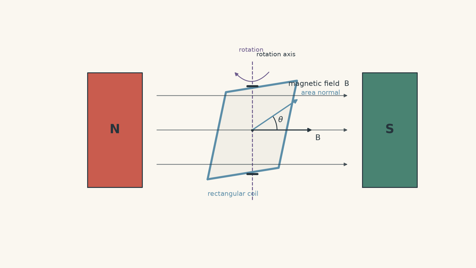
The magnetic field passes through the area enclosed by the coil. How much field passes through depends on the coil’s orientation.
It helps to imagine an arrow sticking straight out of the face of the coil. This is the coil’s area normal.
When that arrow points along the magnetic field, the field passes through the coil as directly as possible. The magnetic flux has its greatest magnitude.
Rotate the coil by \(90^\circ\). The field now runs along the plane of the coil rather than through it. The magnetic flux is zero.
Rotate another \(90^\circ\). The field again passes directly through the coil, but now through the opposite face. We treat the flux as negative.
For one turn,
\[ \Phi = BA\cos\theta \]
where:
- \(\Phi\) is the magnetic flux through the turn, in webers, \(\text{Wb}\)
- \(B\) is the magnetic field strength, in tesla, \(\text{T}\)
- \(A\) is the area enclosed by the turn, in square metres, \(\text{m}^2\)
- \(\theta\) is the angle between the magnetic field and the area normal.
The sign of the flux keeps track of which way the field passes through the coil.
02Why maximum flux gives zero emf
Here is the important prediction.
Suppose the coil is at \(\theta=0^\circ\), so its magnetic flux is at a maximum. Is the induced emf also at a maximum?
No. It is zero.
Faraday’s law says that the induced emf depends on the rate at which magnetic flux changes:
\[ \mathcal{E}=-N\frac{d\Phi}{dt} \]
where \(\mathcal{E}\) is the induced emf in volts, \(\text{V}\), and \(N\) is the number of turns in the coil.
The minus sign comes from Lenz’s law. It tells us that the induced effect acts in a direction that opposes the change producing it.
Think about the top of a hill. Your height is greatest there, but for one instant your vertical position is not changing. Maximum amount does not mean maximum rate of change.
The analogy breaks because magnetic flux is not literally height, but the distinction between a quantity and its rate of change is exactly the useful part.
At \(\theta=0^\circ\), the flux is at the top of its cycle. A tiny rotation changes it only slightly, so its instantaneous rate of change is zero.
At \(\theta=90^\circ\), the flux itself is zero, but it is changing most rapidly. That is where the magnitude of the emf is greatest.
| Coil position | Magnetic flux | Induced emf |
|---|---|---|
| \(\theta=0^\circ\) | maximum positive | zero |
| \(\theta=90^\circ\) | zero | maximum in one direction |
| \(\theta=180^\circ\) | maximum negative | zero |
| \(\theta=270^\circ\) | zero | maximum in the opposite direction |
| \(\theta=360^\circ\) | back to maximum positive | zero |
The signs of the emf depend on which terminal you choose as positive. The sequence of zero, maximum, zero, opposite maximum is the important physics.
03Where the sine wave comes from
Now suppose the coil rotates with constant angular velocity \(\omega\).
Angular velocity tells us how quickly its angle changes:
\[ \theta=\omega t \]
where \(t\) is time in seconds and \(\omega\) is measured in radians per second, \(\text{rad s}^{-1}\).
The flux through one turn is therefore
\[ \Phi=BA\cos(\omega t) \]
and Faraday’s law gives
\[ \mathcal{E}=-N\frac{d}{dt}\left[BA\cos(\omega t)\right]. \]
For constant \(B\), \(A\), and \(\omega\),
\[ \mathcal{E}=NBA\omega\sin(\omega t). \]
So we usually write
\[ \mathcal{E}=\mathcal{E}_{\text{max}}\sin(\omega t) \]
with
\[ \mathcal{E}_{\text{max}}=NBA\omega. \]
This is why an ideal coil rotating at constant speed in a uniform magnetic field produces a sinusoidal emf.
The maximum emf becomes larger if you increase:
- the number of turns, \(N\)
- the magnetic field strength, \(B\)
- the coil area, \(A\)
- the angular velocity, \(\omega\).
The frequency of the electrical output is also set by the rotational frequency. For a simple single-loop model making one electrical cycle per revolution,
\[ \omega=2\pi f \]
where \(f\) is the frequency in hertz, \(\text{Hz}\).
There is one phase detail worth noticing. The equation above assumes that at \(t=0\), the area normal points along the magnetic field. That gives maximum flux and zero emf.
If the coil starts in a different orientation, its emf is still sinusoidal, but the sine wave is shifted in time. You might then describe it using a cosine instead.
04What the slip rings actually do
The rotating coil now has a practical problem. Its two ends are spinning, but the external circuit is stationary.
You cannot simply attach ordinary fixed wires and allow them to twist forever.
An AC generator solves this using two slip rings.
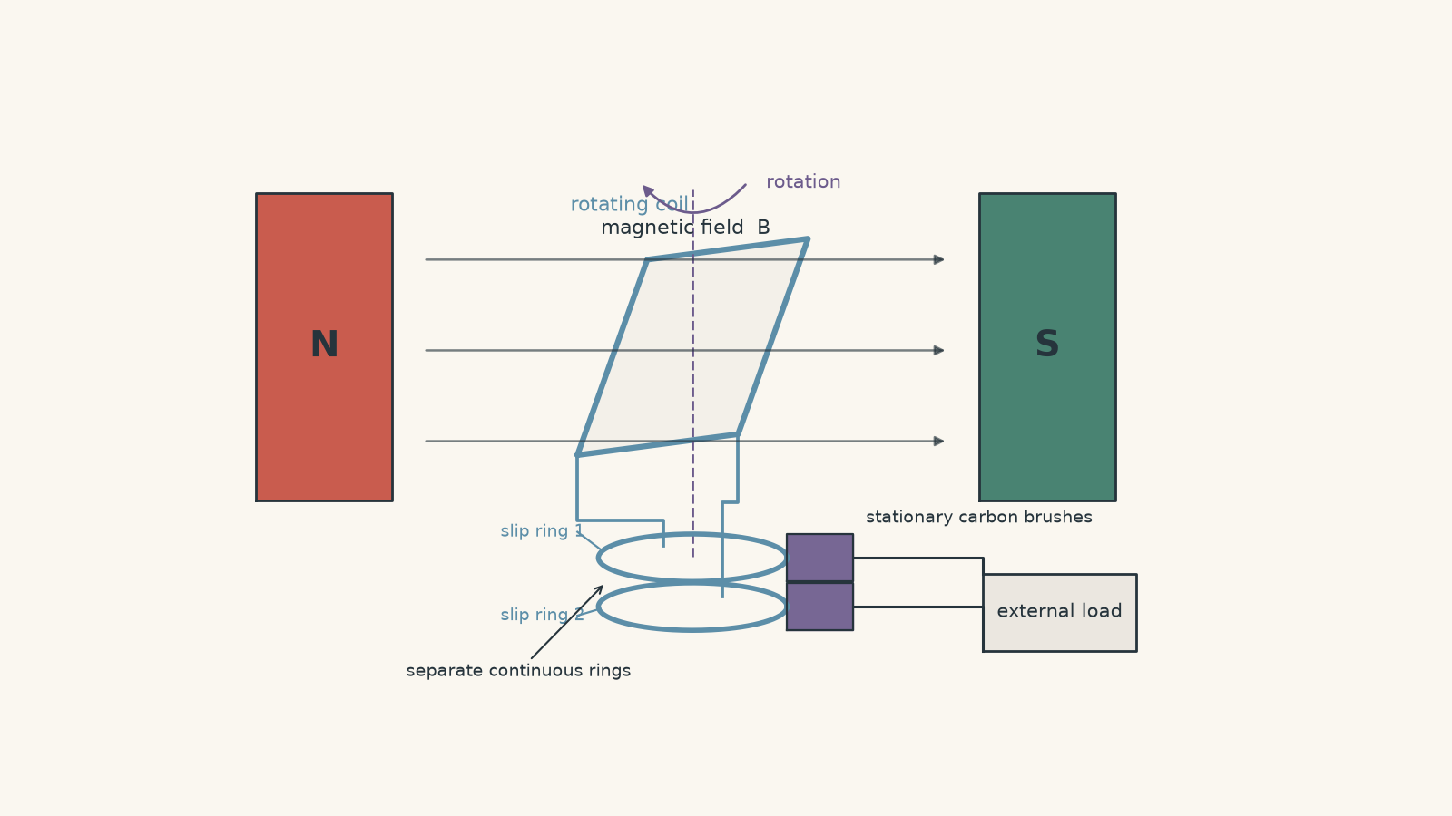
Each end of the rotating coil is connected to its own continuous conducting ring. Both rings rotate with the coil.
Stationary brushes press against the rotating rings. This maintains electrical contact between the spinning coil and the stationary external circuit.
A slightly silly picture helps. Imagine two people standing on a spinning restaurant platform, each holding a separate phone charger. Instead of letting the cables wind themselves into an electrical spaghetti disaster, each charger is connected to its own circular conducting track. A stationary contact can touch each track continuously.
The important part is that the two tracks remain separate. They do not swap partners every half-turn.
That is also where the analogy ends. Real slip rings are conducting machine components, and the brushes make sliding electrical contact with them.
Slip rings do not create the alternating emf
This distinction is commonly muddled.
The induced emf reverses because the direction in which the coil conductors cut through the magnetic field reverses every half-turn. Equivalently, the magnetic flux changes in opposite directions during alternate halves of the rotation.
The slip rings simply preserve the connection between each end of the coil and its corresponding brush.
So this explanation is backwards:
The current alternates because the brushes swap from one slip ring to the other.
They do not.
Each brush remains in contact with its own ring. The electrical polarity arriving at those rings changes because the induced emf in the rotating coil changes direction.
Also be precise with the word current. An emf can exist even if the external circuit is open. An alternating current flows only when there is a complete circuit through which charge can move.
05Slip rings versus a split-ring commutator
This is one of the easiest generator comparisons to lose marks on because the devices look similar.
| Feature | Slip rings | Split-ring commutator |
|---|---|---|
| Structure | two complete conducting rings | conducting ring divided into segments |
| Does each brush remain connected to the same coil end? | effectively yes | no; the external connection is reversed every half-turn |
| What happens to the coil’s naturally reversing emf? | the reversal appears at the external terminals | the external connections reverse at the same time |
| Ideal external output | alternating emf | pulsating emf of one polarity |
| Typical basic application | AC generator | DC generator |
A split-ring commutator does something extra. Every half-turn, it mechanically swaps which coil end contacts each external brush.
That switching can turn the naturally alternating emf of the coil into a pulsating output with one external polarity.
Slip rings do not perform this rectifying action.
06Worked example: Finding the maximum and instantaneous emf
A 200-turn coil has an area of \(3.0\times10^{-3}\text{ m}^2\) and rotates at \(50\text{ Hz}\) in a uniform \(0.40\text{ T}\) magnetic field. At \(t=0\), the area normal is parallel to the magnetic field. Find the maximum induced emf and the emf at \(t=3.0\text{ ms}\).
Step 1
\[ \omega=2\pi f =2\pi(50) =314\text{ rad s}^{-1}. \]
Step 2
Use
\[ \mathcal{E}_{\text{max}}=NBA\omega. \]
Substituting,
\[ \mathcal{E}_{\text{max}} =(200)(0.40)(3.0\times10^{-3})(314) =75.4\text{ V}. \]
So the generator can reach an emf magnitude of about \(75\text{ V}\).
Step 3
Convert milliseconds to seconds:
\[ t=3.0\times10^{-3}\text{ s}. \]
Because the coil started at maximum flux,
\[ \mathcal{E}=\mathcal{E}_{\text{max}}\sin(\omega t). \]
Therefore,
\[ \begin{aligned} \mathcal{E} &=75.4\sin[(314)(3.0\times10^{-3})]\\ &=75.4\sin(0.942)\\ &=61.0\text{ V}. \end{aligned} \]
Step 4
The emf is positive and already fairly close to its maximum. The coil began with zero emf at \(t=0\), and during this part of its rotation the magnetic flux is decreasing increasingly rapidly.
The sign assumes the terminal convention used in our sine equation. Reversing which output terminal is called positive would reverse every emf sign without changing the physics.
07Worked example: Using flux to locate the coil in its cycle
A 120-turn coil of area \(0.015\text{ m}^2\) rotates at \(1500\text{ rpm}\) in a \(0.25\text{ T}\) uniform magnetic field. At \(t=0\), its area normal is parallel to the field, and it begins rotating in the positive \(\theta\) direction.
Find the maximum emf and the instantaneous emf the first time the magnetic flux through each turn has fallen to half its maximum positive value.
Step 1
There are 60 seconds in a minute, so
\[ f=\frac{1500}{60}=25\text{ Hz}. \]
Hence,
\[ \omega=2\pi f =2\pi(25) =157\text{ rad s}^{-1}. \]
Step 2
\[ \begin{aligned} \mathcal{E}_{\text{max}} &=NBA\omega\\ &=(120)(0.25)(0.015)(157)\\ &=70.7\text{ V}. \end{aligned} \]
Step 3
The maximum positive flux through one turn is
\[ \Phi_{\text{max}}=BA. \]
We are told that
\[ \Phi=\frac{1}{2}\Phi_{\text{max}}. \]
Since
\[ \Phi=BA\cos\theta, \]
we have
\[ BA\cos\theta=\frac{1}{2}BA. \]
Therefore,
\[ \cos\theta=\frac{1}{2}. \]
The first time this occurs after \(\theta=0^\circ\) is
\[ \theta=60^\circ. \]
Step 4
\[ \begin{aligned} \mathcal{E} &=\mathcal{E}_{\text{max}}\sin\theta\\ &=(70.7)\sin60^\circ\\ &=61.2\text{ V}. \end{aligned} \]
So the instantaneous emf is approximately \(+61\text{ V}\).
There is a useful trap hiding here. Later in the rotation, at \(300^\circ\), the flux again has the same positive value, \(BA/2\). But the emf is then negative.
Flux alone does not tell you the emf direction. You also need to know whether the flux is increasing or decreasing.
08The most tempting misconception: flux and emf are not the same graph
Students often picture the emf becoming large whenever the flux becomes large.
That would be reasonable if Faraday’s law said that emf depended on flux itself. It does not. It depends on the rate of change of flux.
For our rotating coil,
\[ \Phi=BA\cos(\omega t) \]
while
\[ \mathcal{E}=NBA\omega\sin(\omega t). \]
The two curves are a quarter-cycle, or \(90^\circ\), out of phase.
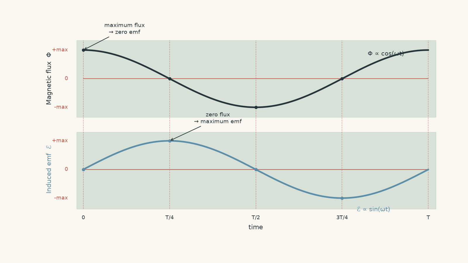
A quick decision rule is useful:
- maximum or minimum flux \(\rightarrow\) zero instantaneous emf
- zero flux during steady rotation \(\rightarrow\) maximum magnitude of emf
- decreasing flux \(\rightarrow\) one emf polarity
- increasing flux \(\rightarrow\) the opposite polarity, for a fixed terminal convention.
Do not memorise those as unrelated facts. They all come from \(\mathcal{E}=-N\,d\Phi/dt\).
09A sine wave requires more than just rotation
The simple equation
\[ \mathcal{E}=\mathcal{E}_{\text{max}}\sin(\omega t) \]
quietly assumes several things:
- the magnetic field is uniform
- the coil geometry stays fixed
- the coil rotates about the intended axis
- the angular velocity is constant.
If the rotational speed changes, the emf need not be a sine wave in time.
For a rotating coil at any instant,
\[ \mathcal{E}=NBA\frac{d\theta}{dt}\sin\theta. \]
Since \(d\theta/dt\) is the instantaneous angular velocity, we can write
\[ \mathcal{E}=NBA\omega\sin\theta. \]
If \(\omega\) itself varies, both the speed at which the coil moves through its cycle and the size of its emf change.
So the statement “a rotating coil produces a sine wave” is a useful first model, but it is not universally true. Constant-speed rotation in the ideal geometry is what produces the standard sinusoidal time dependence.
10What happens when the generator supplies a load?
Once a current flows through the rotating coil, that current is itself in a magnetic field. The motor effect therefore produces a torque on the coil.
By Lenz’s law, this electromagnetic torque opposes the motion driving the generator.
That is why drawing more electrical power from a generator requires more mechanical input if its speed is to remain constant. Energy is being transferred, not created for free.
This same family of ideas appears from the opposite direction when studying motors. In a motor, rotation produces an induced emf that opposes the supplied voltage. You can connect the ideas in Back emf in a DC motor: HSC Physics explained.
11Questions and solutions
Question 1
An 80-turn coil of area \(0.012\text{ m}^2\) rotates at \(20\text{ Hz}\) in a uniform magnetic field of strength \(0.30\text{ T}\).
Calculate the maximum induced emf.
Solution 1
The maximum induced emf is approximately \(36\text{ V}\).
For a coil rotating at constant angular velocity,
\[ \mathcal{E}_{\text{max}}=NBA\omega. \]
First calculate the angular velocity:
\[ \omega=2\pi f =2\pi(20) =125.7\text{ rad s}^{-1}. \]
Then
\[ \begin{aligned} \mathcal{E}_{\text{max}} &=(80)(0.30)(0.012)(125.7)\\ &=36.2\text{ V}. \end{aligned} \]
So
\[ \mathcal{E}_{\text{max}}\approx36\text{ V}. \]
A tempting mistake is to use \(20\) directly as \(\omega\). The given \(20\text{ Hz}\) is revolutions per second, while the generator equation requires angular velocity in radians per second.
Question 2
An AC generator produces a maximum emf of \(50\text{ V}\) while rotating at \(25\text{ Hz}\).
At \(t=0\), the plane of the coil is parallel to the magnetic field, and the emf is at its positive maximum.
Write an equation for the emf as a function of time and determine the first time after \(t=0\) when the emf is zero.
Solution 2
The emf can be written as \(\mathcal{E}=50\cos(50\pi t)\), and its first zero occurs at \(t=0.010\text{ s}\).
The important clue is the starting orientation. If the plane of the coil is parallel to the magnetic field, its area normal is perpendicular to the field. The magnetic flux is therefore zero.
Zero flux during steady rotation is where the magnitude of the emf is greatest. Because the question says the emf is initially positive, the waveform starts at its positive peak.
First calculate the angular frequency:
\[ \omega=2\pi f=2\pi(25)=50\pi\text{ rad s}^{-1}. \]
A cosine starts at its maximum value, so
\[ \mathcal{E}=50\cos(50\pi t). \]
The first zero of cosine occurs when its argument is \(\pi/2\):
\[ \begin{aligned} 50\pi t&=\frac{\pi}{2}\\ t&=\frac{1}{100}\\ &=0.010\text{ s}. \end{aligned} \]
You could also describe the same physical output using a phase-shifted sine function.
The tempting route is to automatically write \(\mathcal{E}=\mathcal{E}_{\text{max}}\sin\omega t\). That form assumes zero emf at \(t=0\). Here the stated starting orientation gives maximum emf instead, so the phase must change.
Question 3
Consider an ideal AC generator connected only to a resistor \(R\). Its coil has constant \(N\), \(B\), and \(A\), and mechanical losses and internal electrical resistance can be neglected.
A motor drives the generator with a constant mechanical torque. Initially the system is rotating steadily at angular velocity \(\omega_1\).
The load resistance is suddenly changed from \(R\) to \(R/2\).
Explain what happens:
- immediately after the resistance changes
- as the generator slows or speeds up
- at the new steady angular velocity.
Determine the new angular velocity in terms of \(\omega_1\), and compare the final rms current with its original value.
Solution 3
The generator initially experiences a larger opposing torque, then slows to \(\omega_1/2\). In the new steady state, its rms current returns to the same value it had before the resistance was halved.
Immediately after the change, the coil cannot instantly change its rotational speed. Its angular velocity is still \(\omega_1\), so its generated emf is initially unchanged.
For the same emf but half the resistance,
\[ I=\frac{\mathcal{E}}{R} \]
means the current initially doubles.
That larger current produces a stronger magnetic force on the current-carrying coil. By Lenz’s law, the resulting electromagnetic torque opposes the generator’s rotation. The generator therefore begins to slow because the driving torque has not increased.
Now find the eventual steady speed.
Let
\[ k=NBA. \]
The peak emf is
\[ \mathcal{E}_{\text{max}}=k\omega. \]
For a sinusoidal emf,
\[ \mathcal{E}_{\text{rms}}=\frac{k\omega}{\sqrt{2}}. \]
The average electrical power supplied to a resistor is therefore
\[ P=\frac{\mathcal{E}_{\text{rms}}^2}{R} =\frac{k^2\omega^2}{2R}. \]
For an ideal generator at steady speed, mechanical power converted to electrical power is
\[ P=\tau\omega, \]
so the opposing electromagnetic torque is
\[ \tau=\frac{P}{\omega} =\frac{k^2\omega}{2R}. \]
Initially,
\[ \tau_{\text{drive}}=\frac{k^2\omega_1}{2R}. \]
After the resistance becomes \(R/2\), the new steady state requires the same constant driving torque:
\[ \frac{k^2\omega_1}{2R} = \frac{k^2\omega_2}{2(R/2)}. \]
Since \(2(R/2)=R\),
\[ \frac{k^2\omega_1}{2R} = \frac{k^2\omega_2}{R}. \]
Therefore,
\[ \omega_2=\frac{\omega_1}{2}. \]
The final generated rms emf is also halved because emf is proportional to angular velocity:
\[ \mathcal{E}_{\text{rms},2} = \frac{1}{2}\mathcal{E}_{\text{rms},1}. \]
But the resistance has also been halved:
\[ \begin{aligned} I_{\text{rms},2} &=\frac{\mathcal{E}_{\text{rms},1}/2}{R/2}\\ &=\frac{\mathcal{E}_{\text{rms},1}}{R}\\ &=I_{\text{rms},1}. \end{aligned} \]
So the final rms current is unchanged.
The tempting answer is “halving the resistance doubles the current”. That is true immediately after the switch, while the rotational speed has not yet changed. It is not true of the final state because the extra electromagnetic braking changes the generator’s speed, and therefore changes its emf.
Question 4
A 100-turn coil of area \(0.020\text{ m}^2\) rotates in a uniform \(0.25\text{ T}\) magnetic field, but its angular speed is not constant.
Using a fixed terminal convention, the generator passes through \(\theta=90^\circ\) with angular speed \(100\text{ rad s}^{-1}\). Later in the same revolution, it passes through \(\theta=270^\circ\) with angular speed \(70\text{ rad s}^{-1}\).
Calculate the emf at each position.
Both positions have zero magnetic flux. Explain why the emf magnitudes are nevertheless different, and decide whether the generator’s emf can be a perfect sinusoid in time during this revolution.
Solution 4
The emfs are \(+50\text{ V}\) at \(90^\circ\) and \(-35\text{ V}\) at \(270^\circ\), and the waveform cannot be a perfect sinusoid in time during this revolution.
For a rotating coil at an instant,
\[ \mathcal{E}=NBA\omega\sin\theta. \]
First calculate the common factor:
\[ NBA=(100)(0.25)(0.020)=0.50. \]
At \(\theta=90^\circ\),
\[ \begin{aligned} \mathcal{E} &=(0.50)(100)\sin90^\circ\\ &=+50\text{ V}. \end{aligned} \]
At \(\theta=270^\circ\),
\[ \begin{aligned} \mathcal{E} &=(0.50)(70)\sin270^\circ\\ &=-35\text{ V}. \end{aligned} \]
At both positions,
\[ \Phi=BA\cos\theta=0. \]
But Faraday’s law does not say that equal flux gives equal emf. It says that emf depends on how rapidly the flux changes.
The coil is moving through the zero-flux position more quickly at \(90^\circ\) than at \(270^\circ\), so the rate of change of flux is larger there.
The output also cannot be a perfect sinusoid in time. A true expression of the form
\[ \mathcal{E}=\mathcal{E}_{\text{max}}\sin(\omega t) \]
requires constant \(\omega\). Here the angular velocity changes, so both the rate at which the phase progresses and the factor multiplying \(\sin\theta\) change during the cycle.
The tempting route is to reason that both positions are “where the emf is maximum” because both have zero flux. That is only true for constant-speed rotation. The geometry makes \(|\sin\theta|=1\), but the instantaneous angular speed still controls how large the emf becomes.
Question 5
Two identical AC-generator coils rotate on the same shaft in the same uniform magnetic field. Each uses its own pair of slip rings.
The second coil is mounted \(90^\circ\) ahead of the first around the shaft. Each coil, when tested alone, produces a sinusoidal emf with a maximum magnitude of \(40\text{ V}\).
The two generators are connected in series so that their instantaneous emfs add.
A student argues that the combined generator must have a maximum emf of \(80\text{ V}\) because each coil can produce \(40\text{ V}\).
Determine the actual maximum combined emf.
Then suppose the two brush connections of the second generator are swapped. Determine whether this allows the combined peak to become \(80\text{ V}\), and explain what this reveals about the role of the slip rings.
Solution 5
The maximum combined emf is \(40\sqrt{2}\text{ V}\), or about \(56.6\text{ V}\). Swapping the brush connections of the second generator does not increase the peak to \(80\text{ V}\); it only changes the phase of the combined waveform.
Let
\[ x=\omega t. \]
Choose the first generator’s emf as
\[ \mathcal{E}_1=40\sin x. \]
Because the second physical coil is mounted \(90^\circ\) ahead, its waveform is also \(90^\circ\) ahead:
\[ \begin{aligned} \mathcal{E}_2 &=40\sin\left(x+\frac{\pi}{2}\right)\\ &=40\cos x. \end{aligned} \]
With the outputs connected so their instantaneous values add,
\[ \mathcal{E}_{\text{total}} =40(\sin x+\cos x). \]
Using
\[ \sin x+\cos x =\sqrt{2}\sin\left(x+\frac{\pi}{4}\right), \]
we get
\[ \mathcal{E}_{\text{total}} = 40\sqrt{2} \sin\left(x+\frac{\pi}{4}\right). \]
Therefore,
\[ \mathcal{E}_{\text{max,total}} =40\sqrt{2} =56.6\text{ V}. \]
The student added the two individual peak values as though those peaks occurred at the same instant.
They do not.
When generator 1 is at its positive \(40\text{ V}\) peak, generator 2 is at zero. The two coils are \(90^\circ\) apart mechanically, so their electrical outputs are \(90^\circ\) out of phase.
In fact, the combined output reaches its maximum when
\[ x=45^\circ \]
for this choice of phase. At that instant,
\[ \mathcal{E}_1 =40\sin45^\circ =28.3\text{ V} \]
and
\[ \mathcal{E}_2 =40\cos45^\circ =28.3\text{ V}. \]
Their sum is
\[ 28.3+28.3=56.6\text{ V}. \]
Now swap the two brush connections of generator 2.
That reverses the sign of its output:
\[ \mathcal{E}_2=-40\cos x. \]
The new total is
\[ \mathcal{E}_{\text{total}} =40(\sin x-\cos x). \]
Since
\[ \sin x-\cos x = \sqrt{2}\sin\left(x-\frac{\pi}{4}\right), \]
the new maximum magnitude is still
\[ 40\sqrt{2}=56.6\text{ V}. \]
The peak has not become \(80\text{ V}\). The waveform has simply shifted in phase.
The hinge is that reversing two external leads can flip a waveform by \(180^\circ\), but it cannot remove a \(90^\circ\) phase difference created by the physical orientation of the coils.
This also exposes what slip rings do, and what they do not do. They provide continuous electrical connections to the rotating coils while preserving each coil’s naturally alternating emf. They do not force separate generators into phase, straighten their waveforms, or make their peak values occur at the same time.
That distinction becomes increasingly important when moving from one simple rotating coil to practical AC generation, where the phase relationships between multiple coils are deliberately controlled.