
Ideal Transformer Voltage and Turns Ratio for HSC Physics
Learn how to use the ideal transformer equation to relate primary and secondary voltage to turns ratio, including step-up and step-down cases.
A transformer can take a small AC voltage and produce a much larger one, even though it has no moving parts and no battery hidden inside. Suppose one coil has 200 turns and the other has 2000. If 24 V AC is applied to the 200-turn coil, what would you predict across the 2000-turn coil: 2.4 V, 24 V, or 240 V?
It is 240 V. The coil with ten times as many turns develops ten times the voltage. That simple pattern is the basis of the ideal transformer voltage equation.
But there is an important catch: the transformer has not created energy. It has traded voltage for current. To use the turns-ratio equation reliably, we first need to understand why the number of turns controls the voltage.
01Why more turns means more voltage
An ideal transformer has two coils wound around the same magnetic core.
- The primary coil is connected to the AC input.
- The secondary coil supplies the output.
- The alternating current in the primary produces a changing magnetic flux through the core.
- That changing flux passes through the secondary and induces a voltage in it.
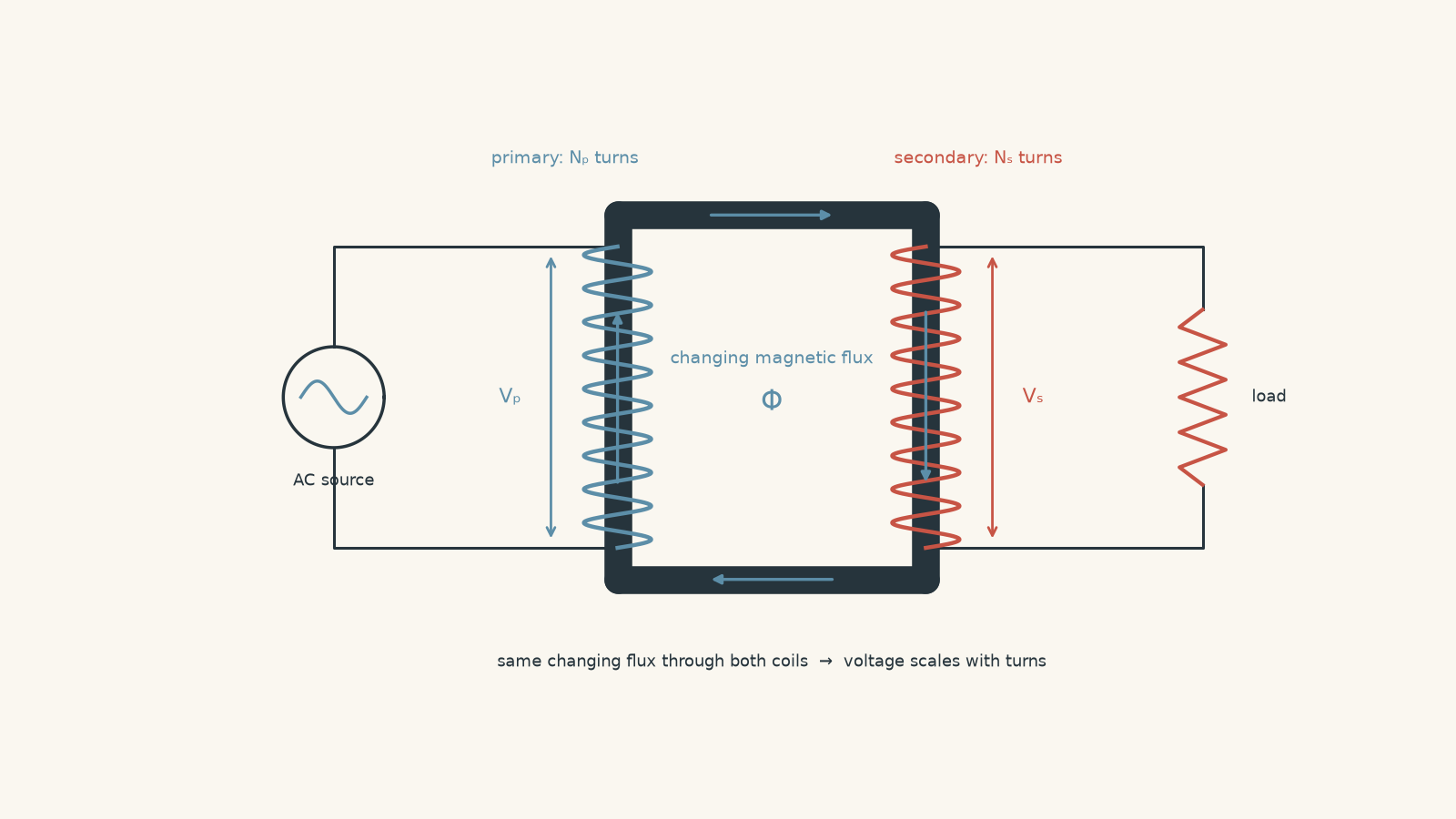
The key idea is that, in an ideal transformer, both coils experience the same rate of change of magnetic flux through the core.
Imagine each turn of wire adding one small piece of induced voltage, a bit like identical cells connected in series. If every turn experiences the same changing flux, doubling the number of turns doubles the total induced voltage.
That analogy is useful, but not exact. The turns are not little batteries producing energy independently. Their induced voltage comes from the changing magnetic flux shared through the core.
This connection comes from Faraday’s law. For a coil of \(N\) turns,
\[ \mathcal{E}=-N\frac{d\Phi}{dt} \]
where:
- \(\mathcal{E}\) is the induced emf in volts, V,
- \(N\) is the number of turns,
- \(\Phi\) is the magnetic flux through each turn in webers, Wb,
- \(\frac{d\Phi}{dt}\) is the rate of change of magnetic flux.
The minus sign describes the direction of the induced emf through Lenz’s law. For transformer voltage ratios, we are normally comparing magnitudes, so the important part is
\[ V\propto N \]
when both coils experience the same changing magnetic flux.
That gives
\[ \frac{V_p}{N_p}=\frac{V_s}{N_s} \]
and therefore
\[ \boxed{\frac{V_p}{V_s}=\frac{N_p}{N_s}} \]
where:
- \(V_p\) is the primary voltage in volts,
- \(V_s\) is the secondary voltage in volts,
- \(N_p\) is the number of primary turns,
- \(N_s\) is the number of secondary turns.
In HSC questions involving sinusoidal AC, the quoted voltages are normally RMS voltages. The same turns ratio also applies to corresponding peak voltages.
02Step-up or step-down?
Before calculating anything, look at the turns.
If the secondary has more turns than the primary, what should happen to the voltage?
Each secondary turn contributes induced emf, so more secondary turns means a larger secondary voltage.
| Turns | Voltage | Transformer behaviour |
|---|---|---|
| \(N_s>N_p\) | \(V_s>V_p\) | Step-up |
| \(N_s<N_p\) | \(V_s<V_p\) | Step-down |
| \(N_s=N_p\) | \(V_s=V_p\) | 1:1 transformer |
A transformer is called step-up or step-down according to what it does to the voltage in its present connection.
That last phrase matters.
The primary is not permanently the coil with more turns or fewer turns. The primary is simply the coil receiving the input. If you reverse the connection, the two coils swap jobs.
A transformer with a 100-turn winding and a 1000-turn winding is:
- step-up if the 100-turn winding is the primary,
- step-down if the 1000-turn winding is the primary.
03A reliable way to use the ratio
Students often know the equation but lose marks by flipping one ratio and not the other.
Keep the same side on top:
\[ \frac{V_p}{V_s}=\frac{N_p}{N_s} \]
Primary goes with primary. Secondary goes with secondary.
You could also invert the entire equation:
\[ \frac{V_s}{V_p}=\frac{N_s}{N_p} \]
That is equally correct.
What you cannot do is write
\[ \frac{V_p}{V_s}=\frac{N_s}{N_p} \]
because that pairs the voltage ratio with the opposite turns ratio.
A useful routine is:
- Identify which winding is receiving the input. That is the primary.
- Decide whether the transformer should step the voltage up or down.
- Write both ratios in the same direction.
- Substitute the numbers.
- Check whether the result agrees with your prediction from the turns.
That final check catches a surprising number of mistakes.
Worked example: Finding the output of a step-down transformer
An ideal transformer has 1200 turns on its primary coil and 100 turns on its secondary coil. The primary is connected to a 240 V AC supply. Calculate the secondary voltage.
Step 1
The secondary has fewer turns:
\[ N_s<N_p \]
so this must be a step-down transformer. The output should be less than 240 V.
Step 2
\[ \frac{V_p}{V_s}=\frac{N_p}{N_s} \]
Step 3
\[ \frac{240}{V_s}=\frac{1200}{100}=12 \]
Step 4
\[ V_s=\frac{240}{12}=20\text{ V} \]
The secondary voltage is \(20\text{ V}\).
This makes physical sense. The secondary has one-twelfth as many turns, so it has one-twelfth the voltage.
04Solving for the number of turns
The same equation can be rearranged when a transformer must produce a particular voltage.
Suppose we need to increase 240 V to 6000 V. The secondary voltage is 25 times the primary voltage, so we should expect the secondary to need 25 times as many turns.
Worked example: Designing a step-up transformer
An ideal transformer is required to increase 240 V AC to 6.0 kV. The primary contains 400 turns. Calculate the required number of secondary turns.
Step 1
\[ 6.0\text{ kV}=6000\text{ V} \]
Step 2
The voltage rises from 240 V to 6000 V, so the secondary must have more turns than the primary.
Step 3
\[ \frac{V_p}{V_s}=\frac{N_p}{N_s} \]
Substituting,
\[ \frac{240}{6000}=\frac{400}{N_s} \]
Step 4
\[ N_s=\frac{400(6000)}{240}=10000 \]
The secondary requires \(10\,000\) turns.
The voltage has increased by a factor of 25:
\[ \frac{6000}{240}=25 \]
and the number of turns has also increased by a factor of 25:
\[ \frac{10000}{400}=25 \]
That agreement is the quickest way to check the result.
05Why the transformer does not create energy
A step-up transformer can make the output voltage much larger than the input voltage. It is tempting to think that this means the transformer has somehow produced extra electrical energy.
It has not.
For an ideal transformer, no energy is lost, so input power equals output power:
\[ P_p=P_s \]
Using \(P=VI\),
\[ V_pI_p=V_sI_s \]
where \(I_p\) and \(I_s\) are the primary and secondary currents in amperes.
So if an ideal transformer increases voltage, the available current decreases correspondingly.
For example, imagine an ideal transformer taking 24 V at 5.0 A:
\[ P_p=(24)(5.0)=120\text{ W} \]
If it steps the voltage up to 240 V, the secondary current must satisfy
\[ 120=(240)I_s \]
so
\[ I_s=0.50\text{ A} \]
Ten times the voltage comes with one-tenth the current.
This is why transformers are so useful in electricity transmission. Voltage can be increased without increasing power, allowing the current to be reduced.
The voltage ratio itself still comes from the changing magnetic flux and number of turns. The transfer of changing flux from one coil to another is called mutual induction.
06The ideal model has limits
The equation
\[ \frac{V_p}{V_s}=\frac{N_p}{N_s} \]
describes an ideal transformer.
The model assumes, among other things, that:
- the magnetic flux produced by the primary links the secondary effectively,
- there are no significant energy losses,
- the coils have negligible resistance,
- the magnetic core does not dissipate energy.
Real transformers have losses due to effects such as resistance in the windings, eddy currents, flux leakage, and hysteresis in the core.
That does not make the ideal equation useless. Quite the opposite: it gives us the main relationship cleanly, then real effects can be treated as departures from that model.
There is another limitation worth noticing. A normal transformer needs changing magnetic flux. A steady DC current eventually produces a steady magnetic field, so it does not continuously induce a secondary voltage. The turns-ratio equation is therefore being used for transformer operation with AC, or another changing input.
07The most tempting mistake: treating “primary” as a particular coil
Consider a transformer with:
- winding A: 1200 turns,
- winding B: 100 turns.
If 240 V is applied to winding A, winding B produces
\[ V_B=240\left(\frac{100}{1200}\right)=20\text{ V} \]
So far, it is a step-down transformer.
Now imagine disconnecting it and applying 20 V AC to winding B instead.
What appears across winding A?
Winding B is now the primary and winding A is now the secondary:
\[ \frac{20}{V_A}=\frac{100}{1200} \]
so
\[ V_A=240\text{ V} \]
The same physical transformer now acts as a step-up transformer.
Nothing inside it had a permanent label saying “I am the primary”. The labels describe the job each winding is doing in the circuit.
08Questions and solutions
Question 1
An ideal transformer has 900 turns on its primary and 150 turns on its secondary. The primary is connected to a 240 V AC supply.
Calculate the secondary voltage and state whether the transformer is step-up or step-down.
Solution 1
The secondary voltage is \(40\text{ V}\), so the transformer is step-down.
The governing relationship is
\[ \frac{V_p}{V_s}=\frac{N_p}{N_s} \]
Substituting the values,
\[ \frac{240}{V_s}=\frac{900}{150}=6 \]
Therefore,
\[ V_s=\frac{240}{6}=40\text{ V} \]
Because \(N_s<N_p\), the secondary voltage must be smaller than the primary voltage.
A tempting mistake is to multiply 240 V by 6 because the turns ratio is 6. But the secondary has fewer turns, not more, so the voltage must decrease rather than increase.
Question 2
An ideal transformer is connected to a 12 V AC source and must produce 3000 V. The winding connected to the source contains 80 turns.
Calculate the required number of turns on the output winding. Explain how you can tell before calculating whether your answer should be greater or less than 80 turns.
Solution 2
The output winding requires \(20\,000\) turns, which must be greater than 80 turns because the transformer is stepping 12 V up to 3000 V.
The input winding is the primary, so
\[ V_p=12\text{ V},\qquad N_p=80 \]
and
\[ V_s=3000\text{ V} \]
Using
\[ \frac{V_p}{V_s}=\frac{N_p}{N_s} \]
gives
\[ \frac{12}{3000}=\frac{80}{N_s} \]
Rearranging,
\[ N_s=\frac{80(3000)}{12}=20000 \]
So
\[ N_s=20\,000\text{ turns} \]
The voltage increases by a factor of
\[ \frac{3000}{12}=250 \]
so the turns must also increase by a factor of 250:
\[ 80(250)=20000 \]
The tempting route is to see “80 turns” and subtract or divide because transformers often reduce household voltages. The actual constraint is the requested voltage change. Since \(V_s>V_p\), an ideal transformer must have \(N_s>N_p\).
Question 3
An ideal transformer has 1500 primary turns and 250 secondary turns. Its primary is connected to a 240 V AC source, and a \(10\,\Omega\) resistor is connected across the secondary.
Calculate:
a. the secondary voltage,
b. the current through the resistor,
c. the secondary power,
d. the current drawn from the primary supply.
Solution 3
The secondary voltage is \(40\text{ V}\), the load current is \(4.0\text{ A}\), the secondary power is \(160\text{ W}\), and the primary current is approximately \(0.67\text{ A}\).
First find the secondary voltage:
\[ \frac{V_p}{V_s}=\frac{N_p}{N_s} \]
so
\[ \frac{240}{V_s}=\frac{1500}{250}=6 \]
Therefore,
\[ V_s=40\text{ V} \]
For the \(10\,\Omega\) load, Ohm’s law gives
\[ I_s=\frac{V_s}{R} =\frac{40}{10} =4.0\text{ A} \]
The secondary power is
\[ P_s=V_sI_s=(40)(4.0)=160\text{ W} \]
For an ideal transformer,
\[ P_p=P_s \]
so
\[ V_pI_p=160 \]
and
\[ I_p=\frac{160}{240}=0.667\text{ A} \]
Therefore,
\[ I_p\approx0.67\text{ A} \]
A common trap is to reason that because the voltage falls by a factor of 6, the current must also fall by a factor of 6. That would reduce both voltage and current, apparently destroying most of the power.
For an ideal transformer, power is conserved. When the voltage decreases, the current increases by the corresponding factor. Here,
\[ \frac{I_s}{I_p}\approx\frac{4.0}{0.667}\approx6 \]
which balances the sixfold decrease in voltage.
Question 4
An ideal transformer contains two windings:
- winding A has 1200 turns,
- winding B has 80 turns.
In the first experiment, 240 V AC is applied to winding A and a \(4.0\,\Omega\) resistor is connected across winding B.
The transformer is then disconnected. In a second experiment, 16 V AC is applied to winding B, and the same \(4.0\,\Omega\) resistor is now connected across winding A.
For each experiment:
a. calculate the voltage across the resistor,
b. calculate the power dissipated by the resistor,
c. calculate the current drawn from the source.
Then explain why the second experiment produces such an extreme result in the ideal model.
Solution 4
In the first experiment the resistor receives \(16\text{ V}\), dissipates \(64\text{ W}\), and the source supplies about \(0.27\text{ A}\). In the second experiment the resistor receives \(240\text{ V}\), dissipates \(14.4\text{ kW}\), and the 16 V source would have to supply \(900\text{ A}\) in the ideal model.
For the first experiment, winding A is the primary:
\[ N_p=1200,\qquad N_s=80,\qquad V_p=240\text{ V} \]
Using the turns ratio,
\[ \frac{240}{V_s}=\frac{1200}{80}=15 \]
so
\[ V_s=16\text{ V} \]
The resistor current is
\[ I_s=\frac{V_s}{R} =\frac{16}{4.0} =4.0\text{ A} \]
Therefore,
\[ P_s=V_sI_s=(16)(4.0)=64\text{ W} \]
For an ideal transformer,
\[ P_p=P_s=64\text{ W} \]
so the source current is
\[ I_p=\frac{64}{240}=0.267\text{ A} \]
or about
\[ I_p=0.27\text{ A} \]
In the second experiment, the windings have swapped roles. Winding B is now the primary:
\[ N_p=80,\qquad N_s=1200,\qquad V_p=16\text{ V} \]
The voltage ratio is
\[ \frac{16}{V_s}=\frac{80}{1200} \]
giving
\[ V_s=240\text{ V} \]
The same \(4.0\,\Omega\) resistor now draws
\[ I_s=\frac{240}{4.0}=60\text{ A} \]
Its power is therefore
\[ P_s=V_sI_s=(240)(60)=14400\text{ W} \]
or
\[ P_s=14.4\text{ kW} \]
The ideal input power must also be \(14.4\text{ kW}\):
\[ V_pI_p=14400 \]
so
\[ I_p=\frac{14400}{16}=900\text{ A} \]
The tempting conclusion is that the calculation must be wrong because 900 A is absurdly large for an ordinary transformer. The mathematics is internally consistent. The problem is that an ideal transformer has no current rating, winding resistance, heating, source resistance, or magnetic limitations.
A real transformer could not behave ideally under such an extreme load. Its windings and source would impose limits, and attempting this arrangement with unsuitable equipment would be dangerous.
The important conceptual result survives: reversing which winding receives the input reverses the voltage transformation.
Question 5
Two ideal transformers are connected in cascade, meaning the output of transformer 1 supplies the input of transformer 2.
Transformer 1 has windings of 600 turns and 150 turns.
Transformer 2 has windings of 80 turns and 400 turns.
A 240 V AC source is connected to one winding of transformer 1. The unused winding of transformer 1 is connected directly to one winding of transformer 2. A voltmeter across the remaining winding of transformer 2 reads 300 V.
a. Determine which winding of transformer 1 must be connected to the 240 V source.
b. Determine which winding of transformer 2 must receive the output from transformer 1.
c. Calculate the voltage between the two transformers.
d. A \(150\,\Omega\) resistor is now connected across the 300 V output. Calculate the current in the resistor and the current drawn from the original 240 V source.
Assume both transformers remain ideal.
Solution 5
Transformer 1 must operate from 600 turns to 150 turns, transformer 2 must operate from 80 turns to 400 turns, the intermediate voltage is \(60\text{ V}\), the final load current is \(2.0\text{ A}\), and the original 240 V source supplies \(2.5\text{ A}\).
The key is not to decide that both transformers must be step-up just because the final voltage, 300 V, is greater than the original 240 V. The total voltage change depends on the product of the two individual ratios.
The required overall voltage ratio is
\[ \frac{300}{240}=1.25 \]
For transformer 1, the two possible output-to-input turns ratios are
\[ \frac{150}{600}=0.25 \]
or
\[ \frac{600}{150}=4 \]
For transformer 2, the possibilities are
\[ \frac{400}{80}=5 \]
or
\[ \frac{80}{400}=0.20 \]
We need a pair whose product is 1.25.
Using transformer 1 as a step-down transformer and transformer 2 as a step-up transformer gives
\[ 0.25\times5=1.25 \]
which exactly matches the measured overall ratio.
Therefore transformer 1 must have the 240 V source connected to its 600-turn winding.
Its 150-turn output voltage is
\[ V=\left(240\right)\left(\frac{150}{600}\right) =60\text{ V} \]
So transformer 2 receives 60 V on its 80-turn winding.
Its output is then
\[ V_s=(60)\left(\frac{400}{80}\right) =300\text{ V} \]
which agrees with the measurement.
With a \(150\,\Omega\) resistor connected to the final output,
\[ I=\frac{V}{R} =\frac{300}{150} =2.0\text{ A} \]
The final output power is
\[ P=(300)(2.0)=600\text{ W} \]
Because both transformers are ideal, that same 600 W must ultimately come from the original source:
\[ P_{\text{source}}=600\text{ W} \]
Therefore,
\[ I_{\text{source}}=\frac{P}{V} =\frac{600}{240} =2.5\text{ A} \]
The tempting route is to compare the first transformer’s 600 turns with the second transformer’s 400 turns, or to reason that a final voltage increase requires every stage to be step-up. Neither works.
Each transformer responds only to the turns ratio of its own input and output windings. Here the first stage deliberately reduces 240 V to 60 V, then the second multiplies 60 V by 5. The combined effect is
\[ 240\text{ V}\rightarrow60\text{ V}\rightarrow300\text{ V} \]
Once that idea is secure, transformer problems become much easier to connect with the deeper physics: Faraday’s law explains why each turn develops induced emf, while mutual induction explains how changing magnetic flux carries the effect from the primary winding to the secondary.