
Ideal Transformer Current and Power for HSC Physics
Learn why ideal transformers conserve power, how voltage and current trade off, and how to use VpIp = VsIs in HSC Physics problems.
A transformer takes 240 V on its primary side and produces 12 V on its secondary side. That sounds like a huge loss of electrical energy: the voltage has fallen by a factor of 20.
So where did the energy go?
Before reading on, make a prediction. If an ideal transformer reduces the voltage by a factor of 20 while transferring the same power, what must happen to the current?
It must increase by a factor of 20. An ideal transformer does not lose power. It trades voltage for current, or current for voltage.
That one idea explains the HSC transformer power equation:
\[ V_p I_p = V_s I_s \]
The important part is understanding why it works, when to use it, and what it does not mean.
01Start with what voltage and current actually measure
Voltage and current describe different things.
Voltage tells you how much electrical energy is transferred per unit charge. One volt is one joule per coulomb.
Current tells you how much charge passes a point each second. One ampere is one coulomb per second.
So when we multiply voltage by current,
\[ VI = \frac{\text{J}}{\text{C}} \times \frac{\text{C}}{\text{s}} = \frac{\text{J}}{\text{s}} = \text{W} \]
we get power.
Power is the rate of energy transfer, measured in watts.
You can picture this using parcels. Imagine each parcel carries some energy, and a conveyor belt delivers a certain number of parcels each second. Voltage is like the energy carried by each parcel. Current is like how many parcels pass each second. Power depends on both.
A transformer can arrange for each coulomb to transfer more energy while fewer coulombs pass each second, or less energy per coulomb while more coulombs pass.
The analogy breaks because electric charge is not actually packaged into separate parcels, and a transformer transfers energy through changing magnetic fields rather than physically moving charge from one coil to the other. But the energy-per-charge × charge-per-second picture is useful.
02Ideal transformers conserve power
An ideal transformer has no energy losses.
That means the electrical power entering the primary equals the electrical power leaving the secondary:
\[ P_p=P_s \]
For the transformer questions considered in the HSC course, electrical power is calculated using \(P=VI\). Therefore,
\[ V_p I_p=V_s I_s \]
where:
- \(V_p\) is the primary voltage, in volts,
- \(I_p\) is the primary current, in amperes,
- \(V_s\) is the secondary voltage, in volts, and
- \(I_s\) is the secondary current, in amperes.
Unless a question tells you otherwise, transformer AC voltages and currents are normally quoted using RMS values.
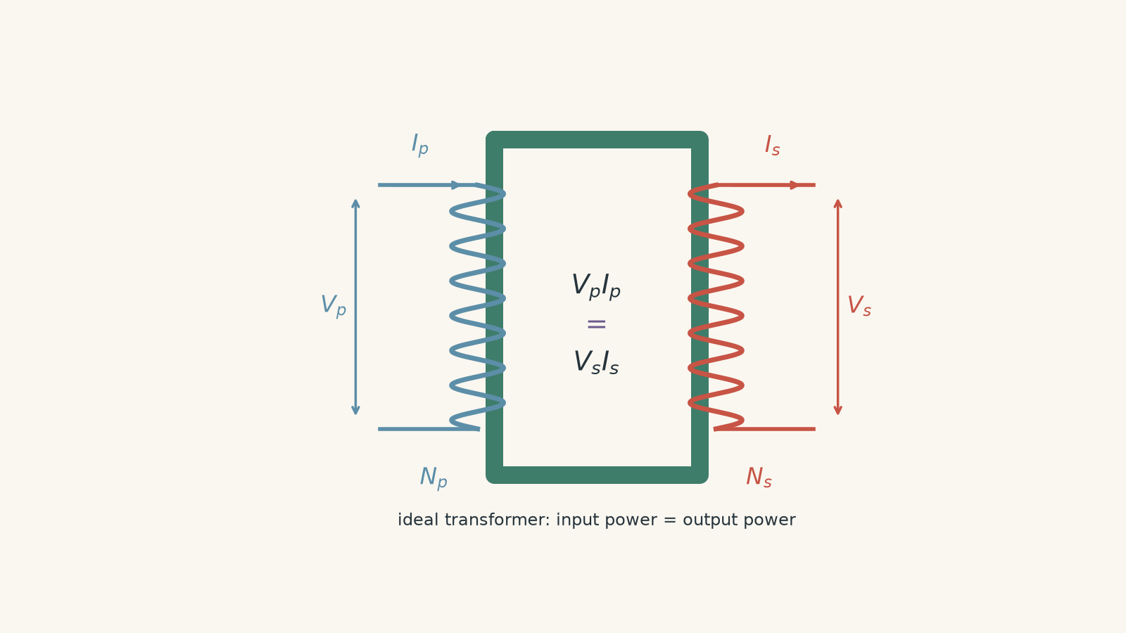
Notice what the equation is saying. It does not say voltage stays constant. It does not say current stays constant.
It says their product stays constant in an ideal transformer operating at a particular transferred power.
03Why voltage and current change in opposite directions
Suppose an ideal transformer doubles the voltage.
For power to remain unchanged,
\[ V_p I_p=V_s I_s \]
so if \(V_s\) is twice \(V_p\), then \(I_s\) must be half \(I_p\).
A step-up transformer therefore produces a higher secondary voltage and a lower secondary current for the same transferred power.
A step-down transformer does the reverse.
| Transformer action | Secondary voltage | Secondary current for the same power |
|---|---|---|
| Step-up | increases | decreases |
| Step-down | decreases | increases |
There is an important qualification in that last column: for the same transferred power.
A transformer does not force a fixed amount of current through whatever you attach to it. The load matters. We will come back to that shortly.
Connecting current ratio to turns ratio
For an ideal transformer,
\[ \frac{V_s}{V_p}=\frac{N_s}{N_p} \]
where \(N_p\) and \(N_s\) are the numbers of turns in the primary and secondary coils.
If you need to refresh why voltage follows the turns ratio, see Ideal Transformer Voltage and Turns Ratio for HSC Physics.
Power conservation gives
\[ V_pI_p=V_sI_s \]
so
\[ \frac{I_s}{I_p} = \frac{V_p}{V_s} \]
Using the voltage ratio,
\[ \frac{I_s}{I_p} = \frac{N_p}{N_s} \]
The current ratio is therefore the inverse of the turns ratio.
For example, if
\[ \frac{N_s}{N_p}=10 \]
then the voltage is stepped up by a factor of 10, while the current is stepped down by a factor of 10 for the same transferred power.
This inverse relationship is easy to reverse accidentally. Rather than memorising two ratios, remember the physical constraint: an ideal transformer cannot create extra power.
Worked example: Finding primary current from a secondary load
An ideal transformer has a primary voltage of \(240\text{ V}\) and a secondary voltage of \(12\text{ V}\). The secondary supplies a current of \(3.0\text{ A}\). Calculate the primary current.
Step 1
\[ P_s=V_sI_s=(12)(3.0)=36\text{ W} \]
The secondary is delivering \(36\text{ W}\).
Step 2
For an ideal transformer,
\[ P_p=P_s=36\text{ W} \]
Step 3
\[ I_p=\frac{P_p}{V_p} =\frac{36}{240} =0.150\text{ A} \]
So the primary current is
\[ I_p=0.15\text{ A} \]
The voltage has fallen from \(240\text{ V}\) to \(12\text{ V}\), a factor of 20. The current is correspondingly 20 times larger on the secondary:
\[ \frac{3.0}{0.15}=20 \]
Nothing mysterious has happened to the energy. The same \(36\text{ W}\) is being transferred at a lower voltage and a higher current.
04The transformer does not create current on its own
A common statement is:
A step-down transformer increases the current.
That is useful shorthand, but it can become misleading.
Suppose a transformer has \(240\text{ V}\) across its primary and \(24\text{ V}\) across its secondary. Now leave the secondary completely disconnected.
What secondary current flows?
Zero.
The transformer can have \(24\text{ V}\) across its secondary terminals while supplying no current at all. With no load connected, there is no closed path for charge to flow.
So the better model is:
- The turns ratio determines the secondary voltage.
- The load and secondary voltage determine the secondary current.
- The power demanded by the secondary load determines the primary current required in the ideal model.
That sequence prevents a lot of transformer mistakes.
Imagine a restaurant has enough pressure in its water pipes to supply a sink. The presence of pressure does not mean water must be flowing. The tap has to provide a path. Similarly, secondary voltage can exist without secondary current.
The analogy stops being useful if you push it too far. Electrical voltage is not literally fluid pressure, and the transformer’s primary and secondary are coupled electromagnetically rather than by a pipe.
05Why does changing the secondary load change the primary current?
This is the strange part.
The primary and secondary coils are not electrically connected. Yet when the secondary load draws more current, the primary also draws more current from its source.
How can one side know what is happening on the other?
The link is the magnetic field.
Alternating current in the primary produces changing magnetic flux through the transformer core. This changing flux induces an emf in the secondary.
When a secondary current begins to flow, that current produces its own magnetic effect. By Lenz’s law, its effect opposes the change that produced it.
The primary source then supplies additional current so that the changing magnetic flux required by the applied primary voltage is maintained.
There is no message travelling through a wire from secondary to primary. The two circuits interact through the shared magnetic flux. If that mechanism is still fuzzy, Mutual Induction Between Solenoids for HSC Physics builds the magnetic picture in more detail.
Worked example: Finding the load from the primary current
An ideal transformer is connected to a \(240\text{ V}\) supply. Its secondary voltage is \(24\text{ V}\). The primary current is \(0.40\text{ A}\), and the secondary is connected to a resistor.
Calculate the secondary current and the resistance of the load.
Step 1
\[ P_p=V_pI_p=(240)(0.40)=96\text{ W} \]
Step 2
\[ P_s=P_p=96\text{ W} \]
Step 3
\[ I_s=\frac{P_s}{V_s} =\frac{96}{24} =4.0\text{ A} \]
Step 4
For the load,
\[ R=\frac{V_s}{I_s} =\frac{24}{4.0} =6.0\ \Omega \]
So the secondary current is \(4.0\text{ A}\), and the load resistance is \(6.0\ \Omega\).
The interesting part is that the primary current contained information about the secondary load. A \(6.0\ \Omega\) resistor on the secondary caused the source on the electrically separate primary side to supply \(0.40\text{ A}\).
06The most tempting misconception: power conservation does not mean fixed power
Suppose an ideal transformer is supplying \(50\text{ W}\) to a load. Then
\[ P_p=P_s=50\text{ W} \]
Now you replace that load with a different one.
Must the transformer still transfer \(50\text{ W}\)?
No.
Power conservation means that, at any particular moment or operating condition, the power entering an ideal transformer equals the power leaving it.
It does not say that a transformer always transfers the same power regardless of the load.
This distinction matters.
A low-resistance secondary load can draw more current and therefore more power. The primary then draws more current too. A high-resistance load draws less. An open circuit draws zero secondary current.
The transformer does not contain a fixed packet of power that has to be shared somehow.
A useful decision rule is:
| If the question gives you… | Think… |
|---|---|
| primary and secondary voltages plus one current | use \(V_pI_p=V_sI_s\) |
| turns ratio | first relate \(V_p\) and \(V_s\) |
| secondary resistance | find \(I_s\) using the load voltage and Ohm’s law |
| primary current and both voltages | use power conservation to infer the secondary load |
| a change in the load | recalculate the power; do not assume it stays fixed |
07What the word ideal is hiding
Real transformers are not perfectly efficient.
Some input energy becomes thermal energy in the windings because they have resistance. Energy is also lost through effects such as eddy currents, hysteresis, and magnetic flux that does not link both coils perfectly.
So for a real transformer,
\[ P_{\text{out}}<P_{\text{in}} \]
For an ideal transformer,
\[ P_{\text{out}}=P_{\text{in}} \]
The ideal model deliberately removes the losses so that you can focus on the relationship between voltage, current, and power.
Do not mix the two models. If a question explicitly gives a transformer efficiency below \(100\%\), you cannot simply set input and output power equal.
08Questions and solutions
Question 1
An ideal transformer has a primary voltage of \(240\text{ V}\) and a secondary voltage of \(48\text{ V}\). The secondary current is \(2.0\text{ A}\).
Calculate:
a. the output power, and
b. the primary current.
Solution 1
The output power is \(96\text{ W}\), and the primary current is \(0.40\text{ A}\).
The governing idea is that an ideal transformer has equal input and output power.
For the secondary,
\[ P_s=V_sI_s=(48)(2.0)=96\text{ W} \]
Therefore,
\[ P_p=96\text{ W} \]
Using \(P_p=V_pI_p\),
\[ I_p=\frac{P_p}{V_p} =\frac{96}{240} =0.40\text{ A} \]
So
\[ P_s=96\text{ W} \]
and
\[ I_p=0.40\text{ A} \]
A tempting mistake is to subtract the voltages or currents because the transformer is “stepping down”. That has no physical basis. Power depends on the product \(VI\), not the difference between primary and secondary values.
Question 2
An ideal transformer connected to a \(240\text{ V}\) supply produces \(30\text{ V}\) across its secondary. A \(15\ \Omega\) resistor is connected across the secondary.
a. Calculate the secondary current.
b. Calculate the power transferred to the resistor.
c. Calculate the primary current.
The \(15\ \Omega\) resistor is then replaced by a \(30\ \Omega\) resistor. Assume the primary supply remains at \(240\text{ V}\).
d. Calculate the new secondary and primary currents.
e. Explain why the transformer now transfers less power even though it is still ideal.
Solution 2
Initially \(I_s=2.0\text{ A}\), \(P=60\text{ W}\), and \(I_p=0.25\text{ A}\). After the resistance is doubled, the currents become \(1.0\text{ A}\) on the secondary and \(0.125\text{ A}\) on the primary.
For the original \(15\ \Omega\) load, use Ohm’s law:
\[ I_s=\frac{V_s}{R} =\frac{30}{15} =2.0\text{ A} \]
The secondary power is
\[ P_s=V_sI_s=(30)(2.0)=60\text{ W} \]
Since the transformer is ideal,
\[ P_p=P_s=60\text{ W} \]
so
\[ I_p=\frac{P_p}{V_p} =\frac{60}{240} =0.25\text{ A} \]
Now replace the load with \(30\ \Omega\). The transformer still produces \(30\text{ V}\) because its primary voltage and turns ratio have not changed.
Therefore,
\[ I_s=\frac{30}{30}=1.0\text{ A} \]
and
\[ P_s=(30)(1.0)=30\text{ W} \]
Thus,
\[ I_p=\frac{30}{240}=0.125\text{ A} \]
The tempting prediction is that an ideal transformer should keep transferring \(60\text{ W}\) because it cannot lose energy. That confuses conservation of power with fixed power.
The new load demands only \(30\text{ W}\). The ideal transformer therefore takes \(30\text{ W}\) from the primary and delivers the same \(30\text{ W}\) to the secondary.
Question 3
An ideal step-up transformer is used to increase an AC voltage from \(240\text{ V}\) to \(12.0\text{ kV}\). It delivers \(6.0\text{ kW}\) of power to its secondary circuit.
a. Calculate the secondary current.
b. Calculate the primary current.
c. A student says, “The voltage has increased by a factor of 50, so the transformer has multiplied the electrical power by 50.” Explain precisely why this conclusion is wrong.
Solution 3
The secondary current is \(0.50\text{ A}\), the primary current is \(25\text{ A}\), and the transformer’s power has not increased.
First convert the given quantities:
\[ 12.0\text{ kV}=12\,000\text{ V} \]
and
\[ 6.0\text{ kW}=6000\text{ W} \]
The secondary current is
\[ I_s=\frac{P_s}{V_s} =\frac{6000}{12\,000} =0.50\text{ A} \]
Because the transformer is ideal,
\[ P_p=P_s=6000\text{ W} \]
so
\[ I_p=\frac{6000}{240}=25\text{ A} \]
The voltage ratio is
\[ \frac{12\,000}{240}=50 \]
while the current ratio is
\[ \frac{25}{0.50}=50 \]
but in the opposite direction. The voltage becomes 50 times larger while the current becomes 50 times smaller.
The student’s argument looks reasonable because \(P=VI\), so increasing \(V\) while imagining \(I\) stays unchanged would increase the power. But \(I\) does not stay unchanged. The current changes inversely with the voltage in the ideal transformer.
The correct comparison is
\[ (240)(25) = (12\,000)(0.50) = 6000\text{ W} \]
The step-up transformer has changed how the power is carried, not created additional power.
Question 4
An ideal transformer has
\[ \frac{N_s}{N_p}=10 \]
and its primary is connected to a \(240\text{ V}\) AC source. A \(4800\ \Omega\) resistor is connected across the secondary.
a. Calculate the secondary voltage and current.
b. Calculate the primary current.
c. From the primary source’s point of view, calculate the effective resistance \(R_{\text{in}}=V_p/I_p\).
Now use the transformer equations and Ohm’s law to show that, for a resistive secondary load \(R_L\),
\[ R_{\text{in}} = \left(\frac{N_p}{N_s}\right)^2R_L \]
d. Explain why this result does not mean that the physical \(4800\ \Omega\) resistor has somehow changed its resistance.
Solution 4
The secondary voltage is \(2400\text{ V}\), the secondary current is \(0.50\text{ A}\), the primary current is \(5.0\text{ A}\), and the primary source behaves as though it is supplying an effective resistance of \(48\ \Omega\).
The turns ratio gives
\[ \frac{V_s}{V_p} = \frac{N_s}{N_p} =10 \]
so
\[ V_s=(10)(240)=2400\text{ V} \]
The secondary load current is
\[ I_s=\frac{V_s}{R_L} = \frac{2400}{4800} = 0.50\text{ A} \]
The output power is
\[ P_s=V_sI_s=(2400)(0.50)=1200\text{ W} \]
For an ideal transformer,
\[ P_p=P_s=1200\text{ W} \]
Therefore,
\[ I_p=\frac{1200}{240}=5.0\text{ A} \]
The effective resistance seen by the primary source is
\[ R_{\text{in}} = \frac{V_p}{I_p} = \frac{240}{5.0} = 48\ \Omega \]
Now derive the general relationship.
For the secondary load,
\[ I_s=\frac{V_s}{R_L} \]
From ideal power conservation,
\[ V_pI_p=V_sI_s \]
so
\[ I_p=\frac{V_sI_s}{V_p} \]
Substituting \(I_s=V_s/R_L\),
\[ I_p = \frac{V_s^2}{V_pR_L} \]
Therefore,
\[ R_{\text{in}} = \frac{V_p}{I_p} = \frac{V_p^2R_L}{V_s^2} \]
Since
\[ \frac{V_p}{V_s} = \frac{N_p}{N_s} \]
we obtain
\[ R_{\text{in}} = \left(\frac{N_p}{N_s}\right)^2R_L \]
For this transformer,
\[ R_{\text{in}} = \left(\frac{1}{10}\right)^2(4800) = 48\ \Omega \]
The difficult part is interpreting that result.
The \(4800\ \Omega\) resistor itself has not become a \(48\ \Omega\) resistor. If you disconnected it and measured its resistance, it would still be \(4800\ \Omega\).
Instead, the transformer changes the relationship between voltage and current seen by the primary source. From the source’s point of view, drawing \(5.0\text{ A}\) at \(240\text{ V}\) is the same \(V/I\) relationship it would have with a \(48\ \Omega\) resistive load.
The tempting route is to think that an ideal transformer only “changes voltage”. Power conservation means it must also change the current presented to the source. That is why a load on one side can appear as a different effective resistance from the other side.
Question 5
An ideal transformer is connected to an ideal \(240\text{ V}\) AC source and has a secondary voltage of \(24\text{ V}\).
Consider three separate situations.
Situation A: The secondary terminals are left open.
Situation B: A \(6.0\ \Omega\) resistor is connected across the secondary.
Situation C: The secondary terminals are connected directly together by an ideal wire with zero resistance.
For each situation, determine what the ideal model predicts for the secondary current and primary current.
Then explain why Situation C does not have a finite steady-state current, and why this does not show that energy conservation has failed.
Assume the standard ideal-transformer model, including zero internal resistance and an ideal primary voltage source.
Solution 5
Situation A has zero secondary and load-related primary current, Situation B has \(I_s=4.0\text{ A}\) and \(I_p=0.40\text{ A}\), while Situation C has no finite steady-state current in the stated ideal model.
In Situation A, the secondary is open.
There is still a secondary voltage of
\[ V_s=24\text{ V} \]
but there is no closed circuit, so
\[ I_s=0 \]
Therefore the power transferred to a load is
\[ P_s=V_sI_s=(24)(0)=0 \]
and in the ideal model the corresponding load-related primary current is also zero:
\[ I_p=0 \]
This is the first important result: voltage can exist without current or power being delivered.
In Situation B,
\[ I_s=\frac{V_s}{R} = \frac{24}{6.0} = 4.0\text{ A} \]
The output power is
\[ P_s=V_sI_s=(24)(4.0)=96\text{ W} \]
so the input power is also
\[ P_p=96\text{ W} \]
and
\[ I_p=\frac{96}{240}=0.40\text{ A} \]
Now consider Situation C.
The wire is specified to have zero resistance. If the ideal transformer still maintains \(24\text{ V}\) across that zero-resistance path, Ohm’s law would require
\[ I_s=\frac{V_s}{R} = \frac{24}{0} \]
There is no finite value for this current.
As \(R\) approaches zero while \(V_s\) remains fixed, the predicted current grows without bound:
\[ I_s\rightarrow\infty \]
The required secondary power,
\[ P_s=V_sI_s \]
also has no finite value, and ideal power conservation would require a correspondingly unbounded primary current.
The tempting response is to argue that this is impossible because the transformer cannot create infinite energy. That objection is pointing at a real problem, but not a failure of conservation of energy.
The problem is the collection of idealisations.
We assumed all of the following at once:
- an ideal source that maintains exactly \(240\text{ V}\) regardless of current,
- an ideal transformer with no internal resistance or other losses, and
- a secondary short circuit with exactly zero resistance.
Those assumptions remove every physical effect that would normally limit the current. The resulting model therefore has no finite steady-state solution.
A real transformer does have winding resistance, leakage effects, source impedance, and other current-limiting behaviour. Its terminal voltage may also fall during a severe short circuit, and protective equipment may disconnect it.
So Situation C exposes the boundary of the ideal model. It does not overturn the rule
\[ P_p=P_s \]
Instead, it shows that conservation of power does not place a fixed upper limit on power when the model also assumes an ideal source capable of supplying unlimited current.
That is the deeper lesson behind \(V_pI_p=V_sI_s\): the equation conserves energy transfer between the two sides, but the amount of power being transferred is still determined by the complete circuit.
09What this lets you understand next
Once \(V_pI_p=V_sI_s\) makes physical sense, the reason transformers are useful in electrical transmission becomes much clearer.
For a fixed amount of transmitted power, increasing the voltage allows the current to decrease. Since heating losses in transmission lines depend strongly on current through the relation \(P_{\text{loss}}=I^2R\), reducing the current can greatly reduce wasted energy.
So the current-power relationship is not just another transformer equation to memorise. It is the bridge between transformer ratios, energy conservation, and why high-voltage transmission works.