
Lenz’s Law for HSC Physics: Predicting Induced Current
Learn how Lenz's law predicts the direction of induced current by opposing changes in magnetic flux, with worked examples and challenging HSC-style questions.
Move the north pole of a bar magnet towards a conducting loop. No battery is connected, but a current appears. Pull the magnet away and the current reverses.
Here is the useful prediction to make before going any further: suppose the magnetic field through a loop points into the page and is getting weaker. Should the loop create a field out of the page to “oppose the magnet”, or into the page to replace what is disappearing?
It creates a field into the page.
That is the central idea of Lenz’s law. The induced effect opposes the change in magnetic flux, not necessarily the magnetic field itself.
01What is Lenz’s law actually opposing?
Imagine a circular wire loop face-on. An external magnetic field passes through it into the page.
If that field gets stronger, more magnetic flux passes into the page. The loop responds by producing its own magnetic field out of the page. That induced field fights the increase.
Now make the external field weaker instead. The amount of flux into the page is falling. This time, the loop produces an induced field into the page. It is trying to prevent the existing flux from disappearing so quickly.
So the same external field direction can produce opposite currents.
A slightly silly way to picture Lenz’s law is as someone who doesn’t hate the situation; they hate the situation changing. If the music gets louder, they turn it down. If it gets quieter, they turn it up. The analogy breaks because a conducting loop has no intention or awareness, of course. The response comes from electromagnetic induction.
The rule is:
The induced current flows in the direction that produces a magnetic field opposing the change in magnetic flux that caused it.
The word change is doing most of the work.
02Start with magnetic flux
Lenz’s law becomes much easier once you stop thinking only about magnetic field and start thinking about magnetic flux.
For a uniform magnetic field passing through a flat loop,
\[
\Phi = BA\cos\theta
\]
where:
- \(\Phi\) is the magnetic flux through one turn, measured in webers (\(\text{Wb}\)),
- \(B\) is the magnetic field strength, measured in teslas (\(\text{T}\)),
- \(A\) is the area of the loop, measured in square metres (\(\text{m}^2\)), and
- \(\theta\) is the angle between the magnetic field and the normal to the loop.
The normal is an imaginary line perpendicular to the plane of the loop. If that last sentence feels annoyingly abstract, the magnetic flux guide builds it from the geometry.
Flux can change because:
- \(B\) changes,
- the area \(A\) changes,
- the angle \(\theta\) changes, or
- the loop moves into or out of a region where the field is different.
Lenz’s law responds to the resulting change in flux. It does not care which of those changes caused it.
That becomes important in harder questions, because two changes can compete.
03The four direction cases
For a loop drawn on the page, use crosses for magnetic field into the page and dots for magnetic field out of the page.
Then there are four basic cases.
| What the external flux is doing | Induced magnetic field | Induced current viewed from the front |
|---|---|---|
| Into the page and increasing | Out of the page | Anticlockwise |
| Into the page and decreasing | Into the page | Clockwise |
| Out of the page and increasing | Into the page | Clockwise |
| Out of the page and decreasing | Out of the page | Anticlockwise |
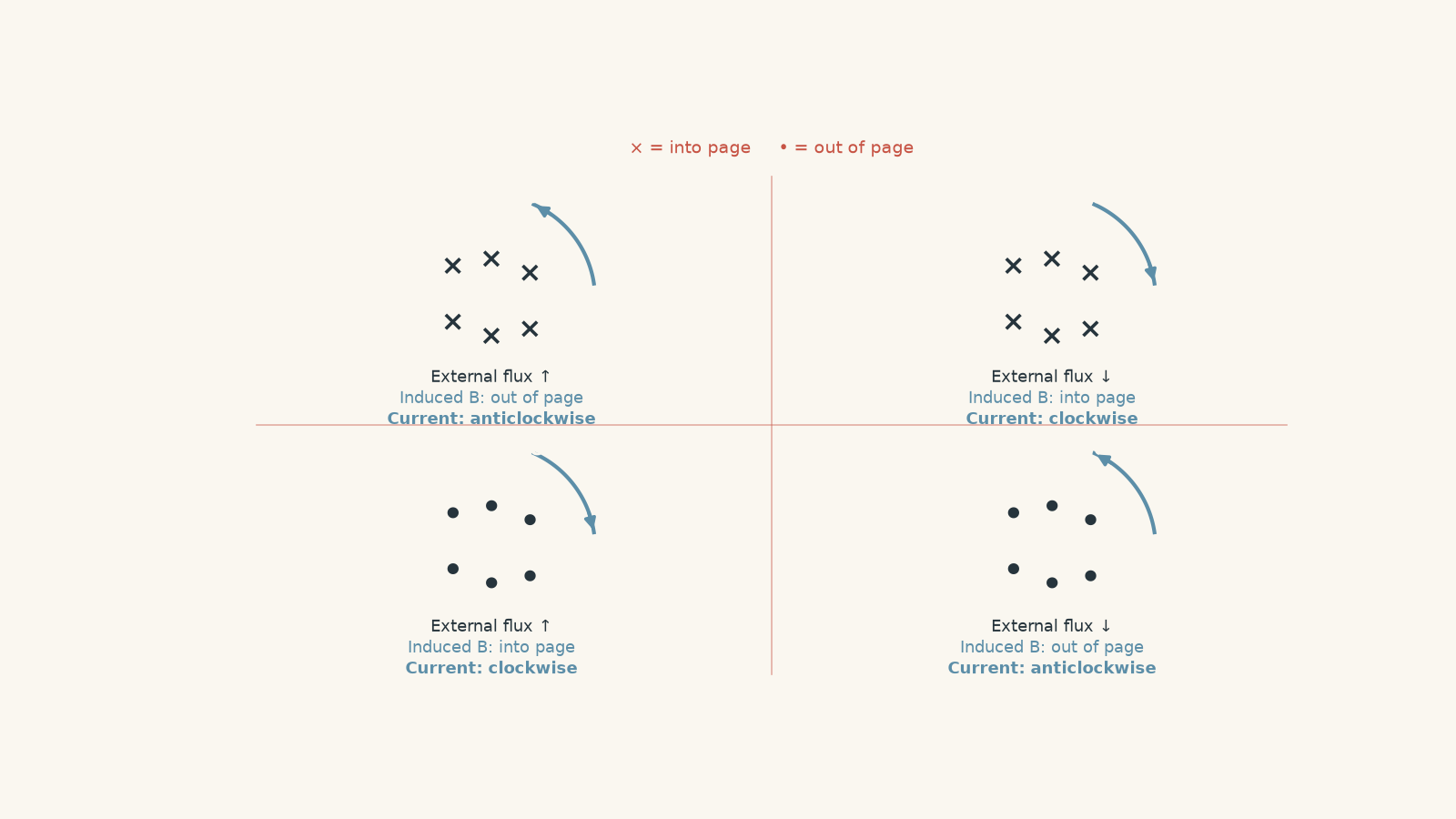
Do not memorise that table as four unrelated facts. There is a much safer method.
04A reliable method for Lenz’s law questions
Step 1: Find the direction of the external magnetic flux
Is the relevant magnetic field through the loop into the page, out of the page, left, right, up, or down?
Do not think about the current yet.
Step 2: Decide whether that flux is increasing or decreasing
This is where many questions are won or lost.
For example:
- a magnet approaching may increase the flux,
- a magnet moving away may decrease it,
- a field getting weaker decreases the flux,
- a loop entering a magnetic-field region gains flux, and
- a loop completely inside a uniform field may have constant flux even while it is moving.
Step 3: Choose the induced magnetic field
Ask: what induced field would oppose that particular change?
For example, if into-page flux is increasing, an out-of-page induced field opposes the increase.
If into-page flux is decreasing, an into-page induced field tries to maintain it.
Step 4: Convert the induced field into current direction
Now use the right-hand grip rule.
Curl the fingers of your right hand in the direction of conventional current. Your thumb points in the direction of the magnetic field produced through the loop.
Therefore:
- anticlockwise current produces a field out of the page, and
- clockwise current produces a field into the page.
Keep the stages separate:
\[
\text{flux change} \rightarrow \text{induced field} \rightarrow \text{induced current}
\]
Trying to jump straight from “magnet moves this way” to “current goes clockwise” is where sign mistakes multiply.
05Why Lenz’s law has to work this way
There is a deeper reason for the opposition: conservation of energy.
Imagine pushing the north pole of a magnet towards a closed conducting loop.
The increasing magnetic flux induces a current. That current produces a magnetic field whose near face behaves like a north pole. The approaching north pole therefore experiences a repulsive force.
You have to do work to keep pushing the magnet forwards.
That mechanical work can become electrical energy in the circuit and, if the wire has resistance, thermal energy.
Now imagine the opposite law existed. Suppose the induced current helped the change instead.
An approaching north pole would induce a field that attracted it. The magnet would accelerate towards the loop. Its faster motion would create a larger flux change, producing a larger current, which would pull the magnet even harder.
You would gain kinetic energy and electrical energy without supplying the corresponding energy.
That cannot happen.
Lenz’s law prevents this runaway process.
There is one qualification worth remembering. When the change in flux is caused purely by relative motion between a magnet and a conductor, the induced magnetic interaction generally resists that motion. But “the force always opposes motion” is not the fundamental law. The fundamental law is that the induced effect opposes the change in flux.
Later, we will see a case where an external power supply is changing the magnetic field and the induced magnetic force can actually act in the same direction as an object’s motion.
06The minus sign in Faraday’s law
Faraday’s law gives the magnitude and sign of the induced electromotive force:
\[
\varepsilon = -N\frac{\Delta\Phi}{\Delta t}
\]
where:
- \(\varepsilon\) is the induced emf in volts (\(\text{V}\)),
- \(N\) is the number of turns,
- \(\Delta\Phi\) is the change in magnetic flux through one turn in webers (\(\text{Wb}\)), and
- \(\Delta t\) is the time over which the change occurs in seconds (\(\text{s}\)).
The minus sign is Lenz’s law written mathematically.
It does not mean that the circuit somehow has a “negative voltage” in an absolute sense. Voltage direction depends on the reference direction you choose. The minus sign tells you that the induced emf acts in the sense that opposes the change in magnetic flux.
For most HSC direction questions, a good approach is:
- calculate the magnitude using Faraday’s law, and
- determine the direction separately using Lenz’s law and the right-hand grip rule.
That usually creates fewer sign errors.
For more detail on calculating the induced emf itself, see Faraday’s law for HSC Physics.
Worked example: Increasing flux into a coil
A 200-turn circular coil experiences magnetic flux into the page that increases from \(1.5\times10^{-4}\ \text{Wb}\) per turn to \(4.5\times10^{-4}\ \text{Wb}\) per turn in \(0.020\ \text{s}\). Calculate the magnitude of the average induced emf and determine the induced current direction when the coil is viewed from the front.
Step 1
\[
|\Delta\Phi|
= |4.5\times10^{-4}-1.5\times10^{-4}|
= 3.0\times10^{-4}\ \text{Wb}
\]
The flux into the page is increasing.
Step 2
\[
|\varepsilon|
= N\frac{|\Delta\Phi|}{\Delta t}
= 200\left(\frac{3.0\times10^{-4}}{0.020}\right)
= 3.0\ \text{V}
\]
Step 3
The external flux into the page is increasing, so the coil must produce a magnetic field out of the page to oppose that increase.
Step 4
A magnetic field out of the page is produced by an anticlockwise current.
The average induced emf is \(3.0\ \text{V}\), and the current is anticlockwise when viewed from the front.
Notice that we did not say, “The field points in, so the current must make a field out.” We said, “The flux into the page is increasing, so the induced field must point out.”
That extra phrase is the difference between Lenz’s law and the common misconception.
Worked example: A weakening field and a resistive coil
A 60-turn coil has an area of \(0.012\ \text{m}^2\) per turn. A uniform magnetic field perpendicular to the coil points into the page and decreases from \(0.80\ \text{T}\) to \(0.20\ \text{T}\) in \(0.15\ \text{s}\). The total resistance of the coil is \(4.0\ \Omega\).
Calculate the magnitude of the average induced emf, the induced current, and its direction when viewed from the front.
Step 1
Because the magnetic field is perpendicular to the coil, \(\cos\theta=1\), so \(\Phi=BA\).
\[
|\Delta\Phi|
= A|\Delta B|
= 0.012(0.80-0.20)
= 7.2\times10^{-3}\ \text{Wb}
\]
Step 2
\[
|\varepsilon|
= N\frac{|\Delta\Phi|}{\Delta t}
= 60\left(\frac{7.2\times10^{-3}}{0.15}\right)
= 2.88\ \text{V}
\]
Step 3
\[
I=\frac{\varepsilon}{R}
=\frac{2.88}{4.0}
=0.72\ \text{A}
\]
Step 4
The external magnetic flux points into the page, but it is decreasing.
The induced field therefore also points into the page. It tries to prevent the into-page flux from falling.
A field into the page requires a clockwise current.
So the induced emf is \(2.88\ \text{V}\), the current is \(0.72\ \text{A}\), and the current is clockwise.
There is nothing contradictory about the induced field pointing in the same direction as the external field. Lenz’s law does not require the two fields to oppose each other. It requires the induced effect to oppose the change.
07The magnet version: approaching and leaving
Suppose the north pole of a magnet faces a conducting loop.
As the north pole approaches, the magnetic flux through the loop increases. The loop produces a magnetic field that opposes that increase. Its near face acts like another north pole, producing repulsion.
Now the magnet passes the loop and starts moving away.
The original flux is now decreasing. The induced current reverses so that the loop tries to maintain the disappearing flux. Its magnetic interaction now attracts the departing magnet.
In both stages, the magnetic force resists the change caused by the magnet’s motion:
- approaching magnet: repulsion,
- departing magnet: attraction.
This is why a magnet falling through a conducting tube can fall much more slowly than you would expect from gravity alone. Mechanical energy is transferred through the induced currents and eventually dissipated as thermal energy.
If the conducting path is cut so that the circuit is open, an emf can still be induced. But there is no sustained path for a substantial current, so the magnetic braking effect becomes much smaller.
That distinction between induced emf and induced current is another common exam trap.
08Three misconceptions worth fixing
“The induced magnetic field always opposes the external magnetic field”
No.
If the external flux is increasing, the induced field opposes its direction.
If the external flux is decreasing, the induced field points in the same direction in an attempt to maintain it.
Always ask what is changing.
“Moving through a magnetic field always creates an induced current”
No.
A loop can move through a perfectly uniform magnetic field while its area, orientation, and field strength remain unchanged.
Then its magnetic flux stays constant:
\[
\Delta\Phi=0
\]
so
\[
\varepsilon=0
\]
for the complete loop.
Motion alone is not enough. Flux must change.
“The induced current tries to stop magnetic flux”
Also no.
A steady magnetic flux causes no induced emf.
Lenz’s law resists a change in flux, not flux itself. Once the flux stops changing, the reason for the induced emf disappears.
09Questions and solutions
Question 1
A circular conducting loop is viewed face-on. A magnetic field directed out of the page is increasing in strength.
Determine the direction of the induced current and explain your reasoning.
Solution 1
The induced current is clockwise.
The external magnetic flux out of the page is increasing. By Lenz’s law, the loop produces an induced magnetic field that opposes this increase, so its induced field must point into the page.
Using the right-hand grip rule, a clockwise conventional current produces a magnetic field into the page.
The tempting mistake is to remember only “opposite field” without checking whether the flux is increasing or decreasing. It works here only because the external out-of-page flux is increasing.
Question 2
A rectangular 40-turn coil moves to the right at \(2.5\ \text{m s}^{-1}\) into a region containing a uniform magnetic field of \(0.60\ \text{T}\) directed into the page. The vertical side of the coil crossing the field boundary is \(0.12\ \text{m}\) long. The total resistance of the coil is \(1.5\ \Omega\).
Assume the coil moves at the stated constant speed.
Determine:
a. the induced emf and current while the coil is entering the magnetic-field region,
b. the direction of the current while it is entering,
c. the current when the whole coil is completely inside the uniform field, and
d. the direction of the current while the coil later leaves the field region at the same speed.
Solution 2
While entering, the induced emf is \(7.2\ \text{V}\), the current is \(4.8\ \text{A}\) anticlockwise, the current is zero once the coil is completely inside the uniform field, and the current is clockwise while the coil leaves.
While the coil enters the field, its area inside the field increases. Therefore, the magnetic flux into the page increases.
For a coil crossing a straight field boundary at constant speed, the rate at which area enters the field is
\[
\frac{\Delta A}{\Delta t}=lv
\]
where \(l=0.12\ \text{m}\) is the length crossing the boundary and \(v=2.5\ \text{m s}^{-1}\) is the speed.
The induced emf is therefore
\[
\varepsilon=NBlv
=40(0.60)(0.12)(2.5)
=7.2\ \text{V}
\]
Using Ohm’s law,
\[
I=\frac{\varepsilon}{R}
=\frac{7.2}{1.5}
=4.8\ \text{A}
\]
The increasing external flux is into the page. The induced field must therefore point out of the page, requiring an anticlockwise current.
When the coil is completely inside the uniform field, its area, orientation, and field strength are all constant. Its flux is therefore constant even though the coil is still moving:
\[
\Delta\Phi=0
\]
so the induced emf and current are zero.
When the coil leaves, the flux into the page decreases. The induced field now points into the page to resist that decrease, so the current becomes clockwise.
A tempting route is to argue that a moving conductor must always have an induced current. The missing condition is a changing magnetic flux through the complete circuit. Once the coil is fully inside a uniform field, there is no such change.
Question 3
A 100-turn conducting loop remains perpendicular to a uniform magnetic field directed out of the page. During a \(0.10\ \text{s}\) interval, the field strength increases from \(0.40\ \text{T}\) to \(0.55\ \text{T}\), while the area enclosed by the loop decreases from \(0.020\ \text{m}^2\) to \(0.014\ \text{m}^2\).
The loop has resistance \(0.50\ \Omega\).
Determine the average induced current, including its direction.
Solution 3
The average induced current is \(0.60\ \text{A}\) anticlockwise.
The important point is that the field strength increases, but magnetic flux does not depend on \(B\) alone. The shrinking area must also be included.
Initially,
\[
\Phi_i=B_iA_i
=(0.40)(0.020)
=8.0\times10^{-3}\ \text{Wb}
\]
per turn.
Finally,
\[
\Phi_f=B_fA_f
=(0.55)(0.014)
=7.7\times10^{-3}\ \text{Wb}
\]
per turn.
Therefore,
\[
\Delta\Phi
=7.7\times10^{-3}-8.0\times10^{-3}
=-3.0\times10^{-4}\ \text{Wb}
\]
The out-of-page flux has actually decreased, despite the increase in magnetic field strength.
The average emf magnitude is
\[
|\varepsilon|
=N\frac{|\Delta\Phi|}{\Delta t}
=100\left(\frac{3.0\times10^{-4}}{0.10}\right)
=0.30\ \text{V}
\]
so
\[
I=\frac{\varepsilon}{R}
=\frac{0.30}{0.50}
=0.60\ \text{A}
\]
Because the out-of-page flux is decreasing, the induced magnetic field points out of the page to resist that decrease.
The current is therefore anticlockwise.
The tempting prediction is “\(B\) increased, so the induced field must oppose \(B\)”. That ignores the simultaneous change in area. Lenz’s law responds to the net change in \(\Phi=BA\), and here the reduction in area slightly outweighs the increase in field strength.
Question 4
A conducting rod of length \(0.50\ \text{m}\) slides without friction to the right along horizontal conducting rails. The rails and rod form a closed rectangular circuit containing a resistor of \(2.0\ \Omega\). All other resistance is negligible.
A uniform magnetic field of \(0.80\ \text{T}\) points into the page. A constant external force of \(0.40\ \text{N}\) pulls the rod to the right.
As the rod moves, the area of the circuit increases.
a. Explain the direction of the induced current and magnetic force on the rod.
b. Calculate the terminal speed of the rod.
c. Calculate the current and rate of thermal energy production at terminal speed.
d. The resistor is replaced by a \(4.0\ \Omega\) resistor while the same constant pulling force is used. Determine the new terminal speed and current. Explain why increasing the resistance does not reduce the terminal current in this situation.
Solution 4
The induced current is anticlockwise, the magnetic force on the rod is to the left, the original terminal speed is \(5.0\ \text{m s}^{-1}\), and doubling the resistance raises the terminal speed to \(10\ \text{m s}^{-1}\) while leaving the terminal current at \(1.0\ \text{A}\).
As the rod moves right, the area enclosed by the circuit increases. The external magnetic field points into the page, so the magnetic flux into the page increases.
Lenz’s law requires an induced field out of the page. The current is therefore anticlockwise.
On the moving right-hand rod, anticlockwise current travels upwards. The magnetic force on that current-carrying rod is to the left, opposing the motion that is increasing the flux.
For a rod moving at speed \(v\) perpendicular to a field,
\[
\varepsilon=Blv
\]
so the current is
\[
I=\frac{Blv}{R}
\]
The magnetic force on the rod has magnitude
\[
F_B=BIl
\]
Substituting the current gives
\[
F_B
=B\left(\frac{Blv}{R}\right)l
=\frac{B^2l^2v}{R}
\]
At terminal speed, acceleration is zero, so the magnetic force balances the applied force:
\[
F_{\text{pull}}=F_B
\]
Therefore,
\[
0.40
=\frac{(0.80)^2(0.50)^2v}{2.0}
\]
and
\[
v
=\frac{(0.40)(2.0)}{(0.80)^2(0.50)^2}
=5.0\ \text{m s}^{-1}
\]
At that speed,
\[
I
=\frac{Blv}{R}
=\frac{(0.80)(0.50)(5.0)}{2.0}
=1.0\ \text{A}
\]
The rate of thermal energy production is
\[
P=I^2R
=(1.0)^2(2.0)
=2.0\ \text{W}
\]
This matches the mechanical power supplied:
\[
P=Fv=(0.40)(5.0)=2.0\ \text{W}
\]
Now replace the resistor with \(R=4.0\ \Omega\).
At terminal speed,
\[
v
=\frac{F_{\text{pull}}R}{B^2l^2}
=\frac{(0.40)(4.0)}{(0.80)^2(0.50)^2}
=10\ \text{m s}^{-1}
\]
The new current is
\[
I
=\frac{Blv}{R}
=\frac{(0.80)(0.50)(10)}{4.0}
=1.0\ \text{A}
\]
So the terminal current is still \(1.0\ \text{A}\).
The tempting argument is that doubling resistance must halve the current. That would be true if the induced emf stayed fixed. It does not.
The larger resistance initially gives a smaller current and therefore a smaller magnetic braking force. The constant external force then accelerates the rod to a greater speed. That greater speed produces a greater induced emf. Terminal motion is reached only when the current becomes large enough for the magnetic force to balance the fixed \(0.40\ \text{N}\) pull again.
In fact, at terminal speed,
\[
F_{\text{pull}}=BIl
\]
so
\[
I=\frac{F_{\text{pull}}}{Bl}
\]
which contains no resistance at all.
The resistance controls the terminal speed required to produce that current.
This is Lenz’s law and energy conservation working together rather than two separate pieces of physics.
Question 5
A 50-turn conducting loop of resistance \(0.50\ \Omega\) lies coaxially to the right of an electromagnet. The electromagnet’s magnetic field through the loop points to the right and is stronger at positions closer to the electromagnet.
The loop is already moving to the right, away from the electromagnet.
At one instant, two processes are changing the external magnetic flux through each turn:
- because the loop is moving away, the rightward magnetic flux is decreasing at \(6.0\times10^{-4}\ \text{Wb s}^{-1}\);
- because the current in the electromagnet is being increased by an external power supply, the rightward magnetic flux is increasing at \(9.0\times10^{-4}\ \text{Wb s}^{-1}\).
Take rightward magnetic flux as positive.
a. Determine the net rate of change of external magnetic flux per turn.
b. Calculate the magnitude of the induced emf and current.
c. An observer is on the right-hand side of the loop, looking back towards the electromagnet. Determine whether the induced current appears clockwise or anticlockwise.
d. Determine whether the magnetic force on the loop is towards or away from the electromagnet at this instant. Hence decide whether the magnetic force opposes or assists the loop’s current motion.
e. What electromagnet-induced rate of increase in flux would make the induced current momentarily zero? Explain what happens to the current and magnetic force if the source contribution becomes slightly smaller than this value.
Assume the induced current is small enough that the stated external flux-change rates can be treated as fixed.
Solution 5
The net rightward flux is increasing at \(3.0\times10^{-4}\ \text{Wb s}^{-1}\), producing a \(0.015\ \text{V}\) emf and a \(0.030\ \text{A}\) clockwise current as viewed from the right. At this instant the induced magnetic interaction pushes the loop away from the electromagnet, so the magnetic force assists its motion rather than opposing it. This does not violate Lenz’s law or conservation of energy.
First combine the two causes of flux change.
Take an increase in rightward flux as positive. The motion contributes
\[
-6.0\times10^{-4}\ \text{Wb s}^{-1}
\]
while the increasing electromagnet current contributes
\[
+9.0\times10^{-4}\ \text{Wb s}^{-1}
\]
Therefore,
\[
\frac{\Delta\Phi}{\Delta t}
=
9.0\times10^{-4}
–
6.0\times10^{-4}
=
3.0\times10^{-4}\ \text{Wb s}^{-1}
\]
The net external flux is increasing to the right.
The induced emf magnitude is
\[
|\varepsilon|
=N\left|\frac{\Delta\Phi}{\Delta t}\right|
=50(3.0\times10^{-4})
=1.5\times10^{-2}\ \text{V}
\]
so
\[
|\varepsilon|=0.015\ \text{V}
\]
The current is
\[
I=\frac{\varepsilon}{R}
=\frac{0.015}{0.50}
=0.030\ \text{A}
\]
Now determine its direction.
The external rightward flux is increasing, so the loop must produce a magnetic field towards the left.
The observer is standing on the right and looking left. A rightward field would point towards that observer, equivalent to out of the page from their viewpoint. The required induced leftward field therefore points away from that observer, equivalent to into the page.
That requires a clockwise current.
Now consider the force.
The electromagnet’s field points right. The induced magnetic field of the loop points left, so the loop’s magnetic moment is opposed to the electromagnet’s field. Since the external field is stronger closer to the electromagnet, this opposed magnetic moment is pushed towards the weaker-field region: away from the electromagnet.
The loop is already moving away, so the magnetic force is in the same direction as its velocity.
That may seem to contradict the familiar statement that “Lenz’s law opposes motion”. It does not.
The loop is not responding only to its own motion. Its motion is trying to decrease the flux, but the powered electromagnet is increasing the flux even faster. The net result is an increasing rightward flux.
The induced current opposes that net increase exactly as Lenz’s law requires.
The extra mechanical and thermal energy can come from the external power supply driving the electromagnet. There is no creation of energy from nowhere.
For the current to become momentarily zero, the two flux-change contributions must cancel:
\[
\left(\frac{\Delta\Phi}{\Delta t}\right)_{\text{source}}
=
6.0\times10^{-4}\ \text{Wb s}^{-1}
\]
At that exact rate,
\[
\frac{\Delta\Phi}{\Delta t}=0
\]
so
\[
\varepsilon=0
\]
and there is no induced current.
If the source contribution falls slightly below \(6.0\times10^{-4}\ \text{Wb s}^{-1}\), the motion-induced decrease becomes the larger effect. The net rightward flux then decreases.
The induced magnetic field reverses and points right, so the current becomes anticlockwise as viewed from the right. The loop’s magnetic moment is now aligned with the external field and it is attracted towards the stronger field near the electromagnet.
That force points left, opposing the loop’s motion away.
The difficult hinge in this question is that Lenz’s law does not ask, “Which way is the object moving?” It asks, “What is happening to the total magnetic flux?”
10What Lenz’s law lets you understand next
Once you can separate external flux change, induced field, and induced current, several HSC electromagnetism ideas become much easier.
Faraday’s law tells you how much emf a changing flux produces. Lenz’s law tells you its sense or direction. The motor effect then tells you what force that induced current can experience in a magnetic field.
Put those together and you can analyse magnetic braking, generators, moving conductors, back emf, and energy transfer without relying on memorised clockwise-or-anticlockwise patterns.
The habit to keep is simple: before touching the right-hand rule, decide exactly what the magnetic flux is doing.