
Ohmic and Non-Ohmic Conductors in HSC Physics
Learn how to interpret current-voltage graphs, identify ohmic and non-ohmic behaviour, calculate resistance, and explain where Ohm's law stops applying.
A resistor is connected to a variable power supply. At 2.0 V, the current is 0.10 A. You increase the potential difference to 4.0 V. What current do you expect?
A tempting answer is 0.20 A. Sometimes that prediction is exactly right. Sometimes it isn’t even close.
The difference is the idea behind ohmic and non-ohmic conductors. You need to be able to look at a current-voltage graph, decide whether resistance stays constant, and explain physically why the relationship can change.
01Start with the simplest prediction
Electric current tells us how quickly charge passes a point. If that idea needs refreshing, see Current as Charge Flow Rate: Using I = q/t in HSC Physics.
Potential difference is related to the energy transferred per unit charge. Increasing the potential difference across a conductor gives its charge carriers a stronger electrical push.
So here is our first useful model:
More potential difference produces more current.
That model is correct, but incomplete. The important question is how much more current?
Imagine one conductor gives these measurements:
| Potential difference \(V\) (V) | Current \(I\) (A) |
|---|---|
| 2.0 | 0.10 |
| 4.0 | 0.20 |
| 6.0 | 0.30 |
| 8.0 | 0.40 |
Every time the potential difference doubles, the current doubles. The ratio \(V/I\) stays unchanged:
\[
\frac{2.0}{0.10}
=
\frac{4.0}{0.20}
=
\frac{6.0}{0.30}
=
20\ \Omega
\]
This is an ohmic relationship.
Now compare it with another component:
| Potential difference \(V\) (V) | Current \(I\) (A) |
|---|---|
| 2.0 | 0.20 |
| 4.0 | 0.32 |
| 6.0 | 0.40 |
| 8.0 | 0.46 |
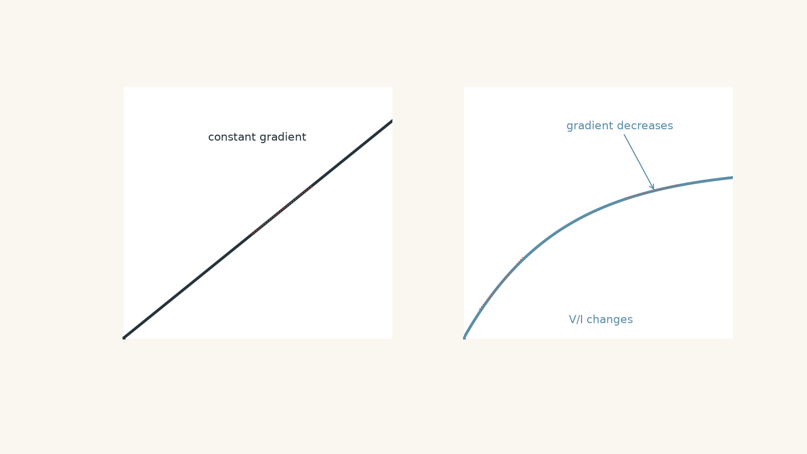
The current still increases, but not in direct proportion to potential difference. The ratio \(V/I\) changes.
That component is non-ohmic over this range.
02What Ohm’s law actually says
Ohm’s law is often introduced as
\[
V = IR
\]
where:
- \(V\) is the potential difference across the conductor, measured in volts (V)
- \(I\) is the current through the conductor, measured in amperes (A)
- \(R\) is the resistance, measured in ohms (\(\Omega\))
But just memorising \(V = IR\) hides the important physics.
For an ohmic conductor, current is directly proportional to potential difference when relevant physical conditions, especially temperature, remain constant:
\[
V \propto I
\]
That means \(V/I\) is constant. That constant is the resistance:
\[
R = \frac{V}{I}
\]
So Ohm’s law isn’t merely saying that you can divide voltage by current. Its useful physical claim is that the resulting resistance remains constant.
Why the temperature condition matters
Picture electrons moving through a metal lattice. The electrons have a small net drift caused by the electric field, while the positive ions in the lattice vibrate around fixed positions.
If the metal becomes hotter, those lattice vibrations become larger. The moving electrons are then scattered more strongly, making their drift more difficult.
A slightly silly picture is trying to walk through a corridor full of people. At first everyone is standing fairly still. Now imagine they all start enthusiastically waving pool noodles. Getting through becomes harder.
The people represent the vibrating lattice ions, and you represent a charge carrier.
The analogy has limits. Electrons in a metal don’t literally follow little obstacle-course paths or undergo classical billiard-ball collisions. The real behaviour is quantum mechanical. But the model captures the useful HSC idea: greater lattice vibration can increase the resistance of a metal.
For a closer look at what the charge carriers are actually doing, see Electric Current in Metals: Charge Carriers and Drift.
03How an ohmic conductor appears on a graph
Suppose current \(I\) is on the vertical axis and potential difference \(V\) is on the horizontal axis.
For an ohmic conductor,
\[
I = \frac{V}{R}
\]
This has the form of a straight-line equation. The graph is therefore a straight line through the origin.
Its gradient is
\[
\text{gradient} = \frac{\Delta I}{\Delta V} = \frac{1}{R}
\]
This point causes a lot of avoidable mistakes.
If the graph is current against potential difference, the gradient is not resistance. It is \(1/R\).
Therefore:
- steeper \(I\)-against-\(V\) line means smaller resistance
- flatter \(I\)-against-\(V\) line means larger resistance
What if the axes are reversed?
Never memorise “gradient equals resistance” without checking the axes.
If potential difference \(V\) is on the vertical axis and current \(I\) is on the horizontal axis, then
\[
V = IR
\]
so
\[
\text{gradient} = \frac{\Delta V}{\Delta I} = R
\]
A compact decision rule is:
| Graph | Gradient for an ohmic conductor |
|---|---|
| \(I\) against \(V\) | \(1/R\) |
| \(V\) against \(I\) | \(R\) |
Before doing any calculation, read the axis labels.
Worked example: Find the resistance from an \(I\)-\(V\) graph
A resistor produces a straight-line graph of current \(I\) against potential difference \(V\). The line passes through the origin and the point \(V = 9.0\text{ V}\), \(I = 0.30\text{ A}\). Determine its resistance.
Step 1
The graph is \(I\) against \(V\), so its gradient would equal \(1/R\). We can also calculate the resistance directly from the coordinates using \(R = V/I\).
Step 2
\[
R = \frac{V}{I}
= \frac{9.0\text{ V}}{0.30\text{ A}}
= 30\ \Omega
\]
Step 3
The resistance is \(30\ \Omega\). Because the graph is a straight line through the origin, the same value of \(V/I\) applies throughout the measured range. The resistor behaves ohmically under those conditions.
04A straight line is not enough if it misses the origin
Suppose an \(I\)-against-\(V\) graph is perfectly straight but would cross the current axis above zero.
Is the component ohmic?
No, not according to the direct proportionality required by Ohm’s law. For direct proportionality,
\[
I \propto V
\]
and the graph must pass through the origin.
A non-zero intercept in experimental data might indicate a measurement offset, another physical effect in the apparatus, or uncertainty. You shouldn’t simply see “straight line” and declare “Ohm’s law”.
The complete check is:
- Is the relationship linear?
- Does the line pass through the origin within reasonable experimental uncertainty?
- Have the relevant physical conditions remained approximately constant?
05Non-ohmic conductors
A non-ohmic conductor or component has a current-voltage relationship in which \(V/I\) is not constant.
Its resistance changes as its operating conditions change.
Common examples include:
- filament lamps
- semiconductor diodes
- thermistors
They can all be non-ohmic, but not for exactly the same reason.
A filament lamp
Consider a filament lamp as you gradually increase its potential difference.
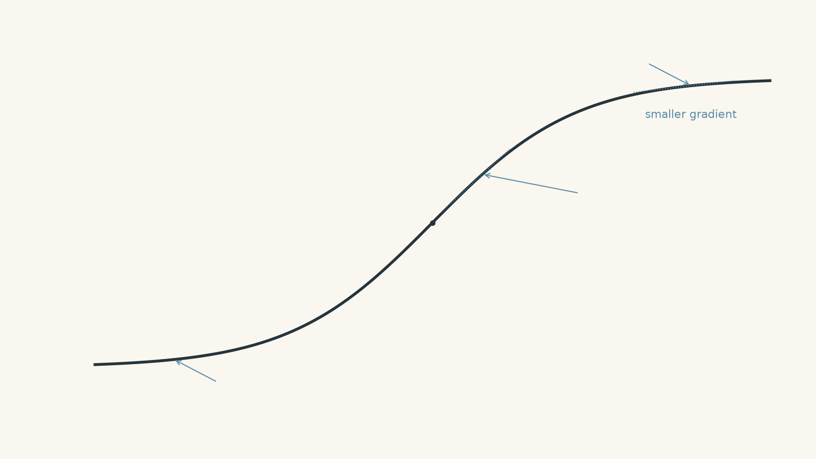
At low current, the filament is relatively cool. As the current increases, electrical energy is converted into thermal energy. The filament’s temperature rises substantially.
Its lattice ions then vibrate more strongly. The filament’s resistance increases.
So if you double the potential difference, the current generally increases by less than a factor of two.
On an \(I\)-against-\(V\) graph, the curve becomes less steep as the magnitude of the voltage increases.
Why? Because
\[
\frac{\Delta I}{\Delta V}
\]
is getting smaller. The component is becoming less responsive to each additional volt as its resistance rises.
Worked example: Show that a lamp is non-ohmic
A filament lamp has a current of \(0.25\text{ A}\) when the potential difference across it is \(2.0\text{ V}\). At \(6.0\text{ V}\), its current is \(0.45\text{ A}\). Determine the resistance at each operating point and explain what the results show.
Step 1
\[
R = \frac{V}{I}
= \frac{2.0\text{ V}}{0.25\text{ A}}
= 8.0\ \Omega
\]
Step 2
\[
R = \frac{V}{I}
= \frac{6.0\text{ V}}{0.45\text{ A}}
= 13.3\ \Omega
\]
to three significant figures.
Step 3
The resistance has increased from \(8.0\ \Omega\) to about \(13.3\ \Omega\).
Step 4
The lamp is non-ohmic over this range because its resistance isn’t constant. Increasing the current heats the filament, increasing its temperature and therefore its resistance.
Notice that the current still increased. “Higher resistance” does not mean “current must decrease”. Both the applied voltage and the resistance changed. The final current depends on both.
06So can you use \(V = IR\) for a non-ohmic component?
This is where the wording can become confusing.
At a particular operating point, you can calculate
\[
R = \frac{V}{I}
\]
for a non-ohmic component. For example, our lamp at \(6.0\text{ V}\) and \(0.45\text{ A}\) had
\[
R = 13.3\ \Omega
\]
The problem is that this value doesn’t remain constant when \(V\) and \(I\) change.
So don’t reason like this:
“I used \(R = V/I\), therefore the component obeys Ohm’s law.”
That conclusion does not follow.
The important test for Ohm’s law is constant resistance, or equivalently, a direct proportionality between \(V\) and \(I\) while the relevant physical conditions remain constant.
07Reading resistance from a curved graph
Suppose a non-ohmic component operates at
\[
V = 5.0\text{ V}, \qquad I = 0.40\text{ A}
\]
Its resistance at that operating point is
\[
R = \frac{V}{I}
= \frac{5.0}{0.40}
= 12.5\ \Omega
\]
On a curved graph, be careful with the word gradient.
The ratio \(V/I\) uses the coordinates of the operating point. It is not generally equal to the tangent gradient of a curved graph.
At HSC level, if you’re asked for the resistance of a component at a stated voltage and current, the safe method is usually
\[
R = \frac{V}{I}
\]
unless the question specifically defines or asks for a different quantity.
This is another reason to avoid the shortcut “resistance is the gradient”. That shortcut only works directly for a \(V\)-against-\(I\) straight-line ohmic graph.
08Diodes show another limit of the simple model
A filament lamp becomes non-ohmic mainly because its temperature changes.
A semiconductor diode behaves differently. Its ability to conduct depends strongly on the direction and size of the applied potential difference.
In one direction, very little current may flow until the forward voltage becomes large enough for current to increase rapidly. In the opposite direction, the current can remain extremely small over the usual operating range.
So a diode’s current-voltage graph isn’t simply a bent version of a resistor graph. It is also asymmetric.
This matters because “non-ohmic” doesn’t describe one particular graph shape. It tells you that the simple constant-resistance relationship does not apply.
09The misconception that resistance “uses up” current
Suppose a filament’s resistance rises while it heats. It can be tempting to say:
“More resistance uses up some of the current.”
That isn’t what happens.
Current is a rate of charge flow. Charge is not gradually consumed by resistance. In a steady series circuit, the same current flows through each series component because charge is conserved.
Resistance instead affects the relationship between potential difference and current.
A resistor can also transfer electrical energy into thermal energy, but transferring energy is not the same as consuming charge. Keeping charge flow and energy transfer separate is essential when you move into circuit power and conservation laws.
10A reliable way to interpret any current-voltage graph
When a graph appears in a question, work in this order.
1. Read the axes
Decide whether you have \(I\) against \(V\) or \(V\) against \(I\).
Do this before thinking about gradient.
2. Look for direct proportionality
A straight line through the origin indicates
\[
V \propto I
\]
and therefore constant resistance, assuming the physical conditions are appropriately controlled.
3. If the graph curves, ask what is changing
A curve means \(V/I\) is changing.
Don’t stop at “it is non-ohmic”. Explain why if the component or context gives enough information.
For a metal filament, heating can increase resistance. For a semiconductor device, the explanation involves its electrical properties rather than simply a hotter metal lattice.
4. Use the coordinates when you need the resistance at one point
Use
\[
R = \frac{V}{I}
\]
with the voltage and current from the same operating point.
5. Don’t confuse gradient with \(V/I\)
For a straight ohmic graph:
- gradient of \(V\) against \(I\) is \(R\)
- gradient of \(I\) against \(V\) is \(1/R\)
For a curved graph, a tangent gradient is not generally the same thing as the resistance \(V/I\).
11Questions and solutions
Question 1
A resistor has a potential difference of \(7.5\text{ V}\) across it and carries a current of \(0.25\text{ A}\). Calculate its resistance.
Solution 1
The resistance at this operating point is \(30\ \Omega\).
Use
\[
R = \frac{V}{I}
\]
where \(V = 7.5\text{ V}\) and \(I = 0.25\text{ A}\).
\[
R
= \frac{7.5\text{ V}}{0.25\text{ A}}
= 30\ \Omega
\]
This calculation alone does not prove that the resistor is ohmic. To establish ohmic behaviour, we would need measurements at multiple potential differences showing that \(V/I\) remains constant under constant physical conditions.
Question 2
Two conductors, A and B, both produce straight-line graphs of current against potential difference through the origin. The gradient for A is \(0.040\text{ A V}^{-1}\), while the gradient for B is \(0.010\text{ A V}^{-1}\).
Calculate the resistance of each conductor and identify which has the greater resistance.
Solution 2
Conductor A has a resistance of \(25\ \Omega\), conductor B has a resistance of \(100\ \Omega\), and B has the greater resistance.
Because the graph is current \(I\) against potential difference \(V\),
\[
\text{gradient} = \frac{\Delta I}{\Delta V} = \frac{1}{R}
\]
For conductor A:
\[
R_A
= \frac{1}{0.040\text{ A V}^{-1}}
= 25\ \Omega
\]
For conductor B:
\[
R_B
= \frac{1}{0.010\text{ A V}^{-1}}
= 100\ \Omega
\]
Therefore,
\[
R_B > R_A
\]
The tempting mistake is to say that A has the larger resistance because its line is steeper. That would be true for a \(V\)-against-\(I\) graph. Here the axes are reversed, so the steeper line corresponds to the smaller resistance.
Question 3
A student records the following results for a small lamp.
| Potential difference \(V\) (V) | Current \(I\) (A) |
|---|---|
| 1.0 | 0.18 |
| 2.0 | 0.30 |
| 4.0 | 0.46 |
Determine whether the lamp behaves ohmically over this range. Support your answer quantitatively and explain the likely physical cause.
Solution 3
The lamp is non-ohmic over this range because its resistance increases as the potential difference and current increase.
Calculate \(R = V/I\) at each operating point.
At \(1.0\text{ V}\):
\[
R
= \frac{1.0\text{ V}}{0.18\text{ A}}
= 5.56\ \Omega
\]
At \(2.0\text{ V}\):
\[
R
= \frac{2.0\text{ V}}{0.30\text{ A}}
= 6.67\ \Omega
\]
At \(4.0\text{ V}\):
\[
R
= \frac{4.0\text{ V}}{0.46\text{ A}}
= 8.70\ \Omega
\]
The resistance is clearly not constant:
\[
5.56\ \Omega,\quad 6.67\ \Omega,\quad 8.70\ \Omega
\]
Therefore \(I\) is not directly proportional to \(V\).
As the current increases, the lamp’s filament becomes hotter. Greater thermal vibration of the metal lattice increases the scattering of charge carriers, so the filament’s resistance rises.
A common wrong conclusion is that the lamp must be ohmic because both current and voltage increase together. Ohm’s law requires direct proportionality, not merely “both quantities increase”.
Question 4
An experiment gives a perfectly straight \(I\)-against-\(V\) graph described by
\[
I = 0.050V + 0.015
\]
where \(I\) is measured in amperes and \(V\) in volts.
A student claims, “The graph is straight, so the conductor obeys Ohm’s law and has a resistance of \(20\ \Omega\).”
Evaluate the student’s claim.
Solution 4
The student’s conclusion that the conductor obeys Ohm’s law is not justified, although \(20\ \Omega\) is the reciprocal of the graph’s gradient.
The gradient is
\[
\frac{\Delta I}{\Delta V}
= 0.050\text{ A V}^{-1}
\]
If this were an ohmic \(I\)-against-\(V\) graph through the origin, then
\[
\frac{1}{R} = 0.050\text{ A V}^{-1}
\]
and hence
\[
R = \frac{1}{0.050} = 20\ \Omega
\]
However, the equation contains a non-zero intercept:
\[
I = 0.050V + 0.015
\]
At \(V = 0\),
\[
I = 0.015\text{ A}
\]
so the line does not pass through the origin. Therefore \(I\) is not directly proportional to \(V\), and \(V/I\) will not be constant.
For example, at \(V = 1.0\text{ V}\),
\[
I = 0.050(1.0) + 0.015 = 0.065\text{ A}
\]
giving
\[
R = \frac{1.0\text{ V}}{0.065\text{ A}}
= 15.4\ \Omega
\]
not \(20\ \Omega\).
The non-zero intercept might result from a measurement offset or another feature of the apparatus. Either way, “straight graph” by itself is not enough to demonstrate Ohm’s law.
Question 5
A filament lamp is operating at point P, where its potential difference is \(3.0\text{ V}\) and its current is \(0.40\text{ A}\).
At point P, a tangent drawn to the lamp’s curved \(I\)-against-\(V\) graph has a gradient of \(0.080\text{ A V}^{-1}\).
A student calculates
\[
R = \frac{1}{0.080} = 12.5\ \Omega
\]
and states that this is the lamp’s resistance at point P.
Determine the resistance using the HSC relationship \(R = V/I\), compare it with the student’s value, and explain why the two calculations differ.
Solution 5
Using \(R = V/I\), the lamp’s resistance at point P is \(7.5\ \Omega\), not \(12.5\ \Omega\). The student’s mistake is treating the tangent gradient of a curved graph as though the component were an ohmic straight-line resistor.
At point P,
\[
V = 3.0\text{ V}
\]
and
\[
I = 0.40\text{ A}
\]
so
\[
R
= \frac{V}{I}
= \frac{3.0\text{ V}}{0.40\text{ A}}
= 7.5\ \Omega
\]
The tangent gradient is
\[
\frac{\Delta I}{\Delta V}
= 0.080\text{ A V}^{-1}
\]
and its reciprocal is
\[
\frac{1}{0.080\text{ A V}^{-1}}
= 12.5\ \Omega
\]
For a straight-line ohmic \(I\)-against-\(V\) graph through the origin, the line’s gradient is constant and equals \(1/R\). A filament lamp’s graph is curved, so that shortcut no longer gives the same quantity as \(V/I\).
The ratio \(V/I\) uses the coordinates of P and gives the resistance associated with that operating point:
\[
R = 7.5\ \Omega
\]
The tangent instead describes how rapidly the current is changing for a very small change in voltage near P. On a non-linear graph, those are different ideas.
That distinction is exactly where the constant-resistance model reaches its limit.
12What this lets you do next
Once you can recognise when resistance is constant and when it changes, circuit questions become much less mechanical. You can decide when \(V = IR\) can be used with one fixed resistance, when a component’s operating point matters, and why electrical heating can change the behaviour of the circuit itself.
The next useful step is to combine these ideas with electrical power. Since
\[
P = VI
\]
an increase in voltage can change the current, the heating rate, the temperature, and therefore the resistance of a non-ohmic component. That feedback is why a real filament lamp cannot always be treated as a simple fixed resistor.