
Torque in HSC Physics: Moment Arms and Rotational Effect
Learn how torque depends on force, distance from the pivot, and angle using \ ( \ tau = rF \ sin \ theta \ ). Includes worked examples, common misconceptions, and challenging HSC-style questions.
You push a heavy door near its hinges and barely anything happens. Push with the same force at the handle and the door swings easily. Same door. Same force. Very different result.
Why?
Before reading on, make a prediction. Suppose you push at the handle, but instead of pushing across the door, you push almost directly towards the hinges. Will the door rotate strongly?
It won’t. A force’s ability to turn an object depends on three things: how large the force is, how far from the pivot it acts, and how much of the force actually acts sideways to the line from the pivot.
That turning effect is torque.
01Start with the turning effect
Picture a door from above. The hinges form the pivot. The handle is far from that pivot.
If you push perpendicular to the door at the handle, nearly all your force is useful for turning it. If you push at the same spot but towards the hinges, the door barely rotates because your force points along the door rather than across it.
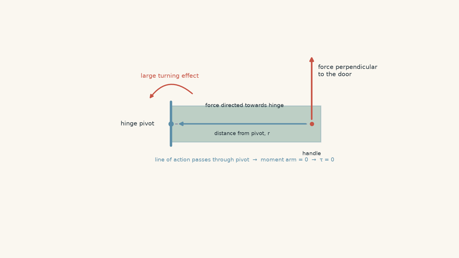
This gives us a useful first model:
- a larger force can create more turning effect,
- applying the force further from the pivot can create more turning effect,
- a force perpendicular to the object is usually more effective than one directed towards or away from the pivot.
That model is useful, but it needs one important correction. Torque does not actually depend on whether the force is “perpendicular to the object”. It depends on the angle between the force and the position vector drawn from the pivot to the point where the force acts.
That distinction matters when rods, beams, spanners, or forces are tilted.
02Torque and the equation \( \tau = rF\sin\theta \)
The magnitude of the torque produced by a force is
\[ \tau = rF\sin\theta \]
where:
- \(\tau\) is the torque, measured in newton metres, \(\mathrm{N\,m}\),
- \(r\) is the distance from the pivot to the point where the force is applied, measured in metres,
- \(F\) is the force, measured in newtons,
- \(\theta\) is the angle between the position vector \(r\) and the force \(F\).
The position vector points from the pivot to the point where the force acts.
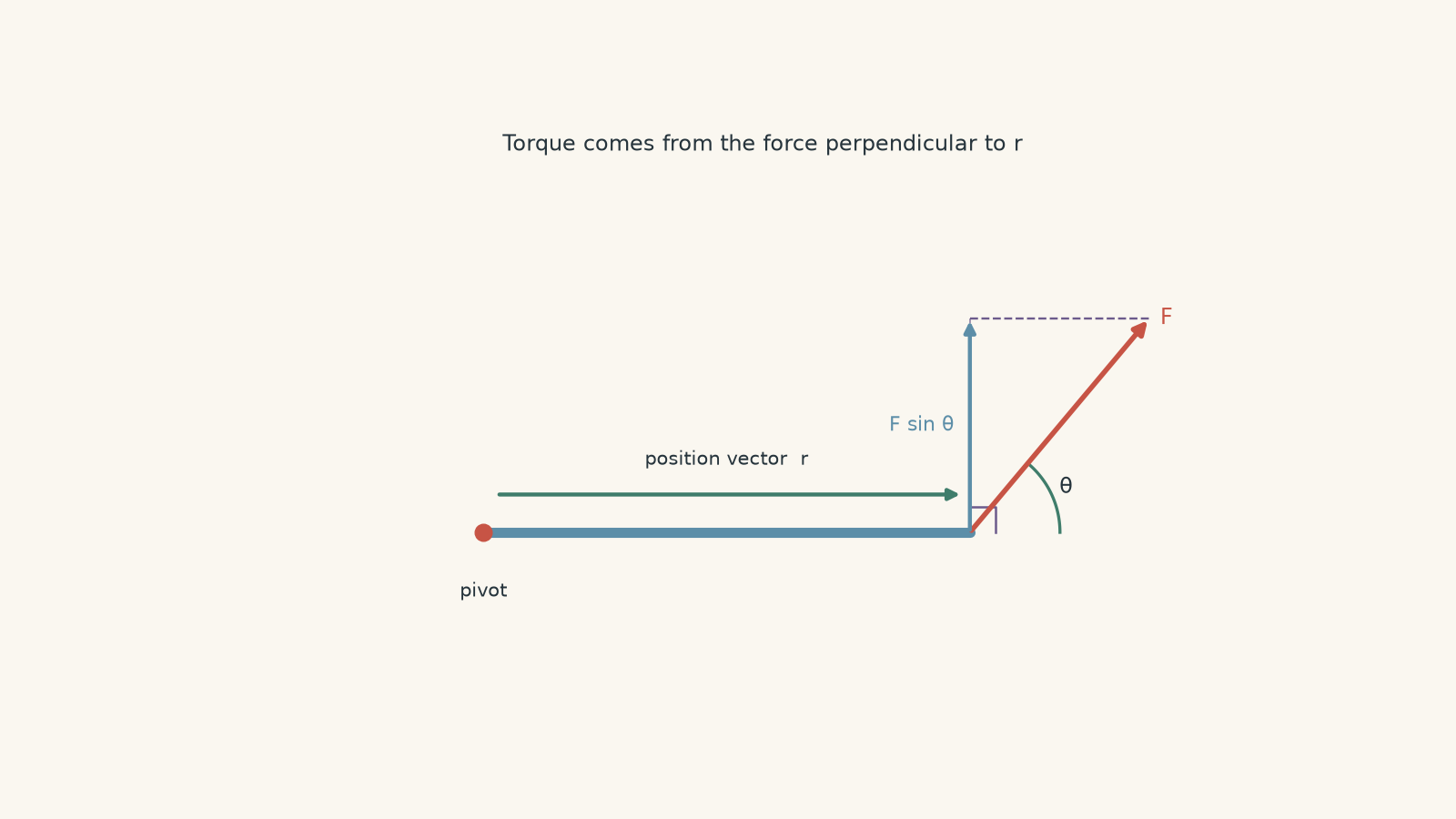
The \(\sin\theta\) is doing something physical. It selects the part of the force that acts perpendicular to \(r\).
You can therefore write
\[ \tau = rF_\perp \]
where
\[ F_\perp = F\sin\theta \]
is the component of the force perpendicular to \(r\).
A force can be enormous, but if it points straight towards the pivot, \(F_\perp=0\), so its torque is zero.
What happens at different angles?
Suppose \(r\) and \(F\) stay the same.
| Angle \(\theta\) | \(\sin\theta\) | Turning effect |
|---|---|---|
| \(0^\circ\) | 0 | Zero |
| \(30^\circ\) | 0.5 | Half the maximum |
| \(90^\circ\) | 1 | Maximum |
| \(180^\circ\) | 0 | Zero |
At \(90^\circ\),
\[ \tau_{\max}=rF \]
because the entire force acts perpendicular to the position vector.
At \(0^\circ\) or \(180^\circ\), the force’s line of action passes through the pivot. There is no turning effect.
03Moment arm: the other way to see torque
There is another version of the torque equation that is often easier to use:
\[ \tau = Fd \]
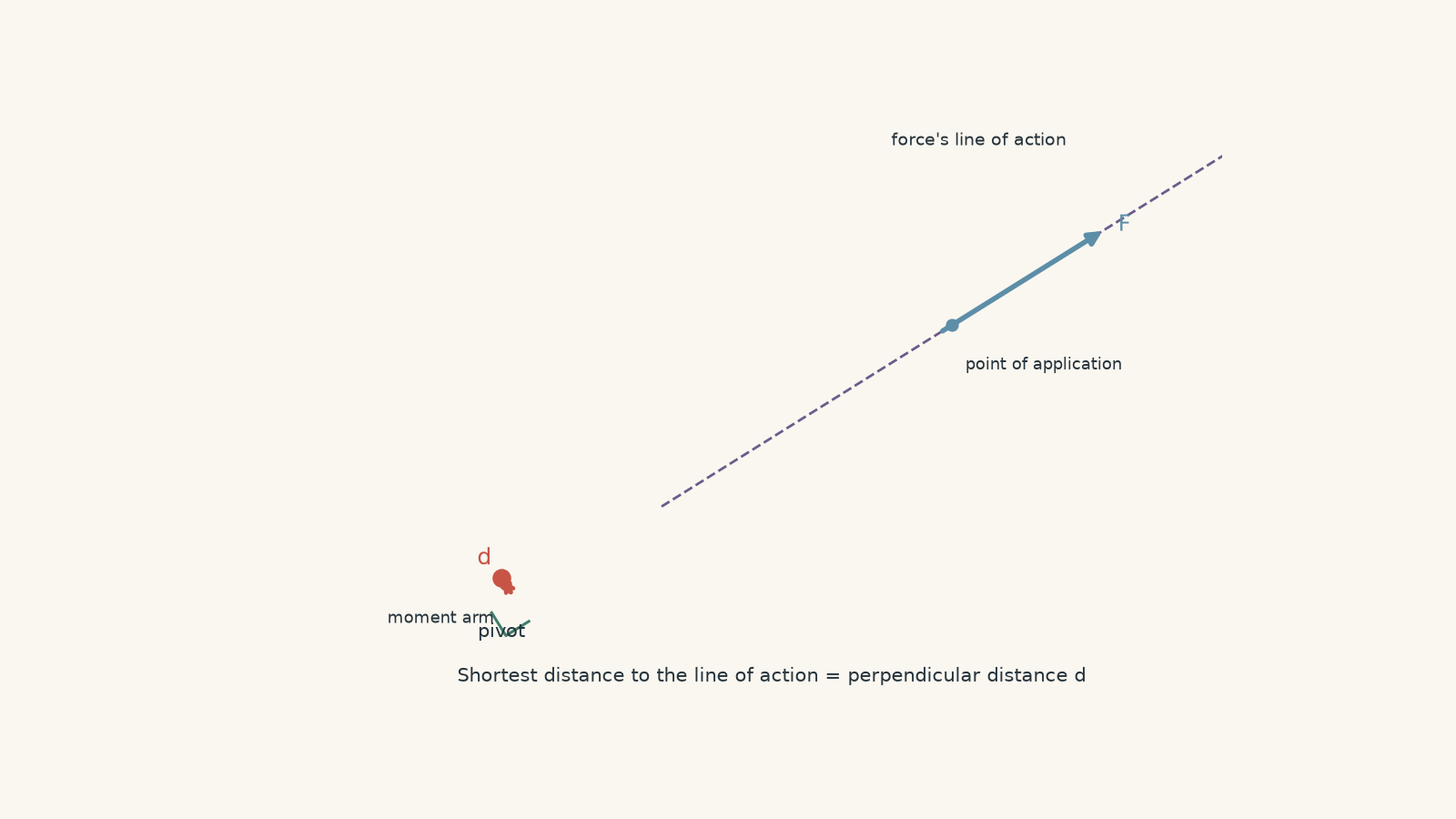
where \(d\) is the perpendicular distance from the pivot to the force’s line of action.
This distance is called the moment arm, or perpendicular moment arm.
The two equations are equivalent because
\[ d=r\sin\theta \]
so
\[ \tau=F(r\sin\theta)=rF\sin\theta \]
This is worth picturing rather than memorising.
Imagine the force’s line of action as an infinitely long piece of string. The moment arm is the shortest distance from the pivot to that string. If the string passes straight through the pivot, the moment arm is zero.
A slightly silly analogy helps. Suppose torque is your ability to make someone turn their head by calling their name from the side. Standing far to one side gives you a decent “turning opportunity”. Standing directly in front of them does not. The analogy breaks because actual torque is caused by forces, not social awkwardness, but the geometry is the useful part: sideways separation matters.
Which form should you use?
Use
\[ \tau=rF\sin\theta \]
when you know the distance \(r\), the force, and the angle between them.
Use
\[ \tau=Fd \]
when the perpendicular distance to the force’s line of action is easier to see.
Do not calculate both unless you are checking your answer.
04Worked example: pushing an angled spanner
A mechanic applies a \(120\,\mathrm{N}\) force to the end of a \(0.80\,\mathrm{m}\) spanner. The force acts at \(60^\circ\) to the spanner. Calculate the torque about the nut.
Step 1
The nut is the pivot, and the force is applied \(0.80\,\mathrm{m}\) away, so
\[ r=0.80\,\mathrm{m} \]
Step 2
The force is at \(60^\circ\) to the spanner, so
\[ \theta=60^\circ \]
Step 3
\[ \begin{aligned} \tau &= rF\sin\theta\\ &=(0.80)(120)\sin60^\circ\\ &=83.1\,\mathrm{N\,m} \end{aligned} \]
The torque is approximately
\[ \tau=83\,\mathrm{N\,m} \]
The result means this angled \(120\,\mathrm{N}\) force has the same turning effect as a perpendicular force of about \(104\,\mathrm{N}\) applied at the same point, because only the perpendicular component contributes to the torque.
Notice that the answer is not \(96\,\mathrm{N\,m}\). That would come from using \(rF\) and silently assuming the force was perpendicular.
05Clockwise and anticlockwise torque
Torque has a direction.
In most HSC problems involving rotation in a plane, you can describe this as:
- clockwise torque,
- anticlockwise torque.
When several forces act, choose a sign convention and stick to it. For example:
- anticlockwise: positive,
- clockwise: negative.
The exact choice does not matter. Consistency does.
The net torque is the sum of all the individual torques:
\[ \tau_{\text{net}}=\sum\tau \]
If clockwise and anticlockwise torques exactly balance,
\[ \tau_{\text{net}}=0 \]
This is the rotational equivalent of balanced forces. An object with zero net torque has no angular acceleration. It could be stationary, or it could already be rotating at constant angular velocity.
Zero net torque does not necessarily mean zero individual torques.
06Worked example: a beam with competing torques
A uniform horizontal beam is \(2.0\,\mathrm{m}\) long and is pivoted at its left end. The beam weighs \(120\,\mathrm{N}\), with its weight acting at its centre. An \(80\,\mathrm{N}\) force acts at the right end at \(50^\circ\) above the beam.
Calculate the net torque about the pivot and state its direction.
Step 1
The beam is uniform, so its weight acts at the centre, \(1.0\,\mathrm{m}\) from the pivot.
The weight acts vertically downward, perpendicular to the horizontal beam.
Taking anticlockwise as positive,
\[ \begin{aligned} \tau_{\text{weight}} &=-(1.0)(120)\sin90^\circ\\ &=-120\,\mathrm{N\,m} \end{aligned} \]
The negative sign means clockwise.
Step 2
The \(80\,\mathrm{N}\) force acts \(2.0\,\mathrm{m}\) from the pivot at \(50^\circ\) to the beam.
\[ \begin{aligned} \tau_F &=(2.0)(80)\sin50^\circ\\ &=122.6\,\mathrm{N\,m} \end{aligned} \]
This force tends to rotate the beam anticlockwise, so its torque is positive.
Step 3
\[ \begin{aligned} \tau_{\text{net}} &=122.6-120\\ &=2.6\,\mathrm{N\,m} \end{aligned} \]
The net torque is approximately
\[ \tau_{\text{net}}=2.6\,\mathrm{N\,m} \]
anticlockwise.
The interesting part is not the tiny answer. It is how that tiny answer appeared. Two large rotational effects almost cancelled.
A student who calculates only the \(80\,\mathrm{N}\) force has missed the beam’s own weight. A student who simply compares \(120\,\mathrm{N}\) and \(80\,\mathrm{N}\) has missed both the distances and the angle.
07The most tempting torque mistakes
Mistake 1: “The biggest force produces the biggest torque”
Not necessarily.
Compare:
- \(200\,\mathrm{N}\) applied \(0.10\,\mathrm{m}\) from a pivot, perpendicular to \(r\),
- \(80\,\mathrm{N}\) applied \(0.50\,\mathrm{m}\) from the pivot, perpendicular to \(r\).
Their torques are
\[ \tau_1=(0.10)(200)=20\,\mathrm{N\,m} \]
and
\[ \tau_2=(0.50)(80)=40\,\mathrm{N\,m} \]
The smaller force produces twice the torque because it acts much further from the pivot.
Mistake 2: “A force far from the pivot must produce a large torque”
Again, not necessarily.
If the force points towards the pivot,
\[ \theta=180^\circ \]
and therefore
\[ \tau=rF\sin180^\circ=0 \]
The application point may be far away, but the perpendicular moment arm is zero.
Mistake 3: using the wrong angle
The angle in
\[ \tau=rF\sin\theta \]
is the angle between \(r\) and \(F\).
It is not automatically the angle to the horizontal, the vertical, the floor, or whatever line looks most convenient in the diagram.
Draw \(r\) from the pivot to the force application point. Then identify the angle between that vector and the force.
Mistake 4: calling torque energy because both use \(\mathrm{N\,m}\)
Torque and energy can both be expressed using the dimensions of newton metres, but they are different physical quantities.
For torque, write \(\mathrm{N\,m}\).
For energy, the derived SI unit is the joule, \(\mathrm{J}\).
A torque of \(20\,\mathrm{N\,m}\) is not the same physical statement as \(20\,\mathrm{J}\) of energy.
08A fast way to analyse any torque diagram
When a torque problem looks messy, do not start punching numbers into \(\tau=rF\sin\theta\).
Work in this order:
- Mark the pivot.
- Treat each force separately.
- Draw or imagine \(r\) from the pivot to that force’s application point.
- Ask whether the force’s line of action passes through the pivot. If it does, its torque is zero.
- Otherwise, find either \(r\) and \(\theta\), or the perpendicular moment arm \(d\).
- Decide whether that force tends to rotate the object clockwise or anticlockwise.
- Add the signed torques.
The third and fourth steps prevent a surprising number of mistakes.
09Questions and solutions
Question 1
A student uses a \(0.35\,\mathrm{m}\) wrench to turn a bolt. They apply a \(65\,\mathrm{N}\) force perpendicular to the wrench.
Calculate the torque about the bolt.
Solution 1
The torque is \(22.8\,\mathrm{N\,m}\).
Because the force is perpendicular to the wrench, the angle between \(r\) and \(F\) is \(90^\circ\). Therefore,
\[ \begin{aligned} \tau&=rF\sin\theta\\ &=(0.35)(65)\sin90^\circ\\ &=22.75\,\mathrm{N\,m} \end{aligned} \]
So, to an appropriate number of significant figures,
\[ \tau=23\,\mathrm{N\,m} \]
The common trap is to look for an extra trigonometric step even though the force is already perpendicular. Since \(\sin90^\circ=1\), the torque is simply \(rF\).
Question 2
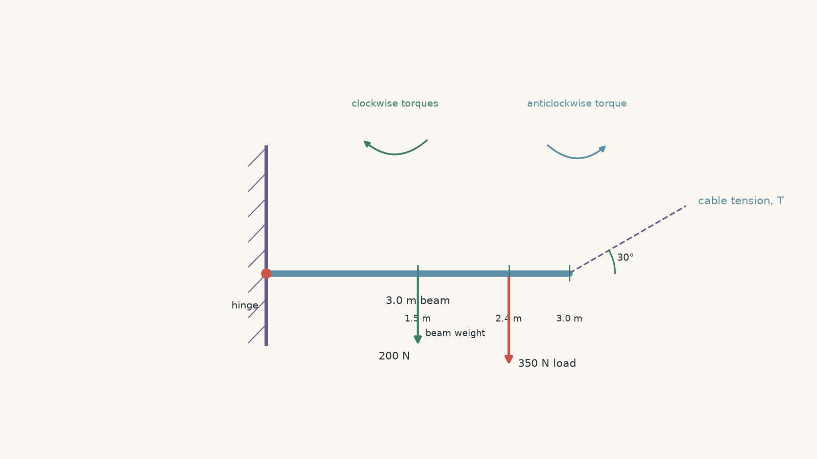
A uniform horizontal beam is \(3.0\,\mathrm{m}\) long and is hinged at its left end. The beam weighs \(200\,\mathrm{N}\). A \(350\,\mathrm{N}\) load hangs \(2.4\,\mathrm{m}\) from the hinge.
A cable attached to the far end of the beam pulls upwards at \(30^\circ\) above the beam.
Assuming the beam is in rotational equilibrium, calculate the tension in the cable.
Solution 2
The cable tension is \(760\,\mathrm{N}\).
For rotational equilibrium,
\[ \tau_{\text{net}}=0 \]
so the cable’s anticlockwise torque must equal the total clockwise torque.
The beam’s weight acts at its centre, \(1.5\,\mathrm{m}\) from the hinge:
\[ \tau_{\text{beam}}=(1.5)(200)=300\,\mathrm{N\,m} \]
The hanging load produces
\[ \tau_{\text{load}}=(2.4)(350)=840\,\mathrm{N\,m} \]
The total clockwise torque is therefore
\[ 300+840=1140\,\mathrm{N\,m} \]
The cable acts \(3.0\,\mathrm{m}\) from the hinge and at \(30^\circ\) to the beam:
\[ \tau_{\text{cable}}=(3.0)T\sin30^\circ \]
For equilibrium,
\[ \begin{aligned} (3.0)T\sin30^\circ&=1140\\ (3.0)T(0.5)&=1140\\ 1.5T&=1140\\ T&=760\,\mathrm{N} \end{aligned} \]
The tempting mistake is to write the cable torque as \(3.0T\), as though the full tension were perpendicular to the beam. It is not. Only the perpendicular component \(T\sin30^\circ\) produces torque about the hinge.
The cable’s horizontal component does not contribute to the torque because it acts along the beam, so its line of action passes through the hinge.
Question 3
A student can apply a \(120\,\mathrm{N}\) force to a spanner in either of two ways.
- Method A: apply the force \(0.50\,\mathrm{m}\) from the pivot at an angle of \(25^\circ\) to the spanner.
- Method B: apply the same force \(0.35\,\mathrm{m}\) from the pivot, perpendicular to the spanner.
Which method produces the greater torque?
Then determine the acute angle at which the \(120\,\mathrm{N}\) force would need to act \(0.50\,\mathrm{m}\) from the pivot to produce the same torque as Method B.
Solution 3
Method B produces the greater torque, and Method A would need an angle of approximately \(44^\circ\) to match it.
For Method A,
\[ \begin{aligned} \tau_A &=rF\sin\theta\\ &=(0.50)(120)\sin25^\circ\\ &=25.4\,\mathrm{N\,m} \end{aligned} \]
For Method B,
\[ \begin{aligned} \tau_B &=(0.35)(120)\sin90^\circ\\ &=42.0\,\mathrm{N\,m} \end{aligned} \]
Therefore Method B produces the greater torque even though the force is applied closer to the pivot.
To find the angle required at \(0.50\,\mathrm{m}\), set the torque equal to \(42.0\,\mathrm{N\,m}\):
\[ \begin{aligned} (0.50)(120)\sin\theta&=42.0\\ 60\sin\theta&=42.0\\ \sin\theta&=0.700 \end{aligned} \]
For the requested acute angle,
\[ \theta=\sin^{-1}(0.700)=44.4^\circ \]
So
\[ \theta\approx44^\circ \]
The tempting prediction is that applying the force further from the pivot must always give the larger torque. Distance helps, but only the perpendicular part of the force counts. In Method A, the poor angle wastes enough of the \(120\,\mathrm{N}\) force for Method B to win.
Question 4
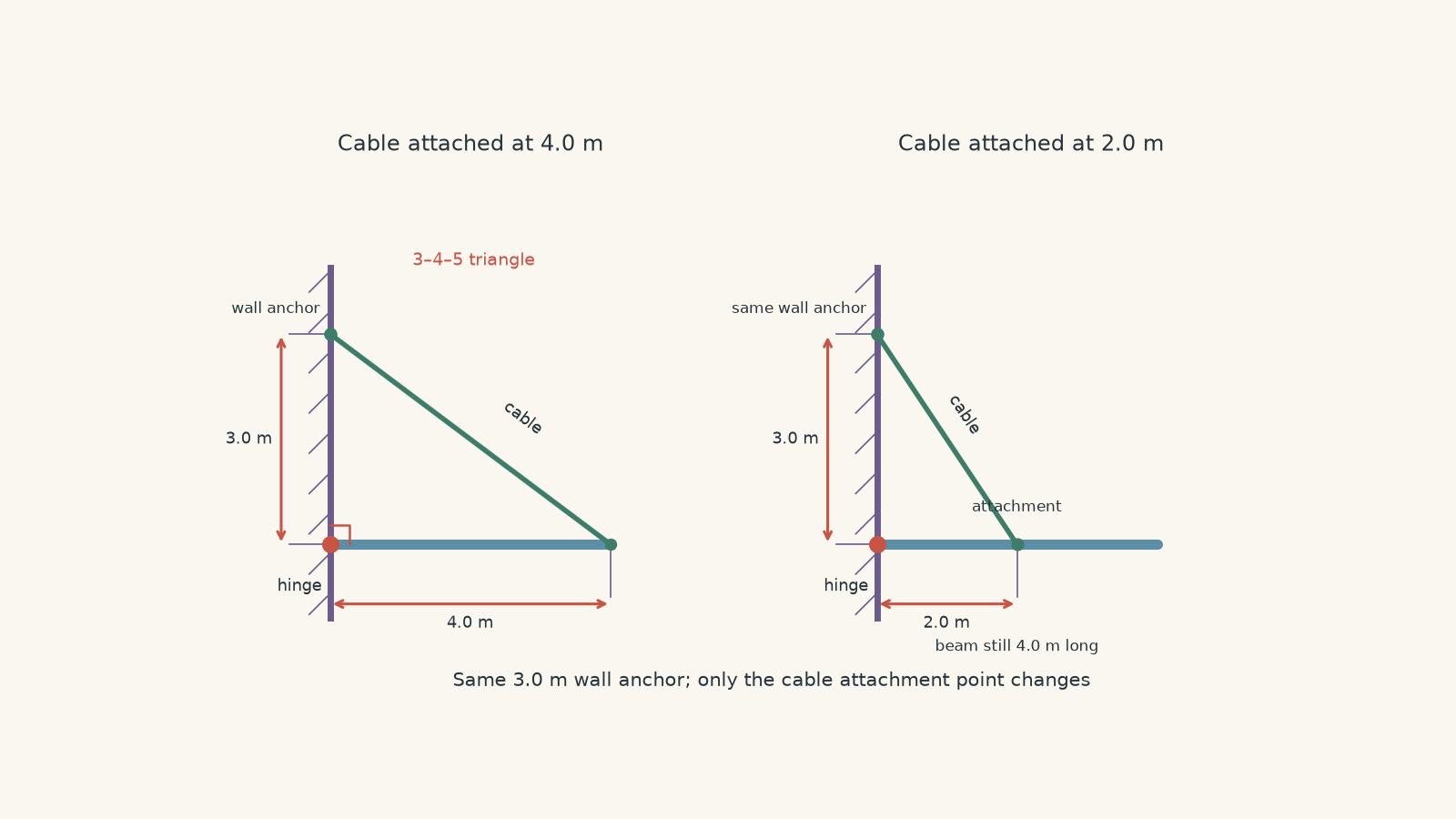
A \(4.0\,\mathrm{m}\) horizontal beam is hinged to a wall. A cable joins the outer end of the beam to a point on the wall \(3.0\,\mathrm{m}\) above the hinge.
The beam weighs \(200\,\mathrm{N}\), acting at its centre, and a \(600\,\mathrm{N}\) load hangs \(3.0\,\mathrm{m}\) from the hinge.
First, calculate the cable tension required for rotational equilibrium.
The cable is then detached from the outer end and reattached \(2.0\,\mathrm{m}\) from the hinge, while remaining connected to the same point \(3.0\,\mathrm{m}\) above the hinge. The beam and load positions do not change.
Calculate the new cable tension.
A student argues that the second tension must be smaller because the cable is now closer to perpendicular to the beam. Explain why that argument fails.
Solution 4
The original cable tension is approximately \(917\,\mathrm{N}\), while the new tension is approximately \(1.32\,\mathrm{kN}\). The second tension is larger, even though its angle is more favourable.
The clockwise torque caused by the beam is
\[ \tau_{\text{beam}}=(2.0)(200)=400\,\mathrm{N\,m} \]
The load produces
\[ \tau_{\text{load}}=(3.0)(600)=1800\,\mathrm{N\,m} \]
So the cable must provide
\[ \tau_{\text{cable}}=400+1800=2200\,\mathrm{N\,m} \]
of anticlockwise torque.
For the original cable, the geometry forms a \(3\)-\(4\)-\(5\) triangle, so
\[ \sin\theta=\frac{3}{5} \]
The cable acts \(4.0\,\mathrm{m}\) from the hinge:
\[ \begin{aligned} (4.0)T_1\left(\frac35\right)&=2200\\ 2.4T_1&=2200\\ T_1&=916.7\,\mathrm{N} \end{aligned} \]
Hence
\[ T_1\approx917\,\mathrm{N} \]
After the cable is moved, its horizontal separation from the wall is \(2.0\,\mathrm{m}\) and its vertical separation is \(3.0\,\mathrm{m}\). Its length is therefore
\[ \sqrt{2.0^2+3.0^2}=\sqrt{13}\,\mathrm{m} \]
so
\[ \sin\theta=\frac{3}{\sqrt{13}} \]
The new torque equation is
\[ \begin{aligned} (2.0)T_2\left(\frac{3}{\sqrt{13}}\right)&=2200\\ T_2&=\frac{2200\sqrt{13}}{6}\\ &=1322\,\mathrm{N} \end{aligned} \]
Thus
\[ T_2\approx1.32\,\mathrm{kN} \]
The student’s argument notices a real effect but ignores another one.
Yes, the second cable is more nearly perpendicular to the beam, so a greater fraction of its tension contributes to torque. But it is also attached only \(2.0\,\mathrm{m}\) from the hinge instead of \(4.0\,\mathrm{m}\).
The useful quantity is not angle by itself. It is the whole moment arm:
\[ d=r\sin\theta \]
Originally,
\[ d_1=(4.0)\left(\frac35\right)=2.40\,\mathrm{m} \]
After the cable is moved,
\[ d_2=(2.0)\left(\frac{3}{\sqrt{13}}\right)=1.66\,\mathrm{m} \]
The cable has become more perpendicular, but its perpendicular moment arm has still become shorter. To create the same \(2200\,\mathrm{N\,m}\) torque with a shorter moment arm, the tension must increase.
This is why comparing angles alone can give a confident but wrong answer.
Question 5
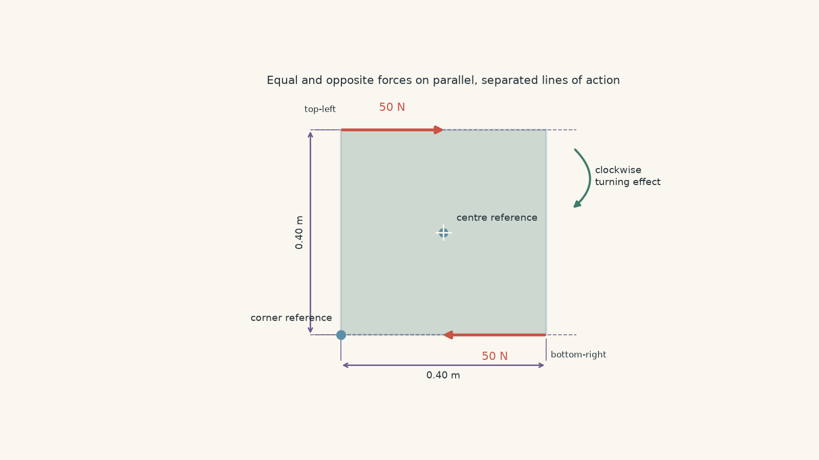
A square plate has side length \(0.40\,\mathrm{m}\).
A \(50\,\mathrm{N}\) horizontal force acts to the right at the top-left corner. A second \(50\,\mathrm{N}\) horizontal force acts to the left at the bottom-right corner.
The two forces are therefore equal in magnitude and opposite in direction.
- Determine the net force on the plate.
- Calculate the net torque about the centre of the square.
- Calculate the net torque about the bottom-left corner.
- A student says, “Torque depends on the pivot, so the two net torques must be different.” Explain why the student’s rule works for a single force but fails for this pair of forces.
Assume clockwise torque is negative.
Solution 5
The net force is zero, and the net torque is \(20\,\mathrm{N\,m}\) clockwise about both the centre and the bottom-left corner.
The surprising part is that changing the point about which torque is calculated does not change the net torque for this particular pair of forces.
First, the forces are equal and opposite:
\[ F_{\text{net}}=50-50=0\,\mathrm{N} \]
They do not produce a net linear force.
Now calculate torque about the centre.
Each horizontal force has a perpendicular moment arm of \(0.20\,\mathrm{m}\), because each line of action lies \(0.20\,\mathrm{m}\) above or below the centre.
The top force produces clockwise torque:
\[ \tau_{\text{top}}=-(50)(0.20)=-10\,\mathrm{N\,m} \]
The bottom force also produces clockwise torque:
\[ \tau_{\text{bottom}}=-(50)(0.20)=-10\,\mathrm{N\,m} \]
Therefore,
\[ \begin{aligned} \tau_{\text{net}} &=-10-10\\ &=-20\,\mathrm{N\,m} \end{aligned} \]
So the net torque is
\[ 20\,\mathrm{N\,m} \]
clockwise.
Now use the bottom-left corner as the reference point.
The top force acts along a horizontal line \(0.40\,\mathrm{m}\) above this point, giving
\[ \tau_{\text{top}}=-(50)(0.40)=-20\,\mathrm{N\,m} \]
The bottom force’s line of action passes directly through the bottom-left reference point. Its perpendicular moment arm is therefore zero:
\[ \tau_{\text{bottom}}=0 \]
Hence,
\[ \tau_{\text{net}}=-20+0=-20\,\mathrm{N\,m} \]
Again, the plate experiences a net torque of
\[ 20\,\mathrm{N\,m} \]
clockwise.
The tempting argument is that torque always changes when the reference point changes. For an individual force, that is generally true: changing the reference point changes its perpendicular moment arm.
But these two forces form a special combination called a couple. They are equal, opposite, and have different parallel lines of action.
When the reference point shifts, one force may gain moment arm while the other loses moment arm. Because their net force is zero, those changes cancel exactly. The net torque of the couple remains the same.
You can see the contrast by removing the bottom force. With only the top \(50\,\mathrm{N}\) force present, its torque would be \(10\,\mathrm{N\,m}\) clockwise about the centre but \(20\,\mathrm{N\,m}\) clockwise about the bottom-left corner. A single force does depend on the chosen reference point.
The deeper lesson is that torque is not simply “force times distance from a pivot”. It depends on the complete geometry of every force and its line of action.
10What torque lets you understand next
The equation
\[ \tau=rF\sin\theta \]
is really a statement about which part of a force can change rotational motion. The radial component points towards or away from the pivot and produces no torque about that pivot. The perpendicular component is the part that can produce a turning effect.
That idea connects neatly to circular motion. A purely centripetal force points towards the centre of the circle, so its torque about the centre is zero even though it continuously changes the direction of the object’s velocity. If you want to sharpen that distinction, see Centripetal Force: How to Identify the Real Force in HSC Physics and Centripetal Acceleration: Why It Points Inward in HSC Physics.
The next useful step is rotational equilibrium: using \(\sum\tau=0\) alongside force balance to analyse beams, supports, hinges, and other systems where an object must avoid both sliding and rotating.