
Ohm’s Law in HSC Physics: When Resistance Is Constant
Learn how to use V = IR correctly, recognise when resistance changes, and interpret ohmic and non-ohmic behaviour from data and graphs.
A resistor is connected to a 6.0 V supply and carries 0.30 A. Now the voltage is doubled to 12.0 V. What should happen to the current?
Your first prediction is probably 0.60 A. For an ordinary resistor kept under the same physical conditions, that’s exactly what Ohm’s law predicts. But connect a filament globe instead, and doubling the voltage usually does not double the current.
So the useful question isn’t just “Can I use \(V = IR\)?” It is: can I treat \(R\) as constant while the voltage and current change?
That distinction is the whole point of Ohm’s law.
01Start with what the circuit is doing
Three quantities are involved:
- potential difference, \(V\), measured in volts (V), tells us the electrical energy transferred per unit charge
- current, \(I\), measured in amperes (A), tells us the rate of charge flow
- resistance, \(R\), measured in ohms (\(\Omega\)), describes how strongly a component opposes that current
If current itself is still a bit slippery, revise current as a charge flow rate first.
A simple mental model is a school turnstile. Imagine students trying to move through it.
A bigger driving effect can make more students pass each second, while a more restrictive turnstile reduces the rate. In the circuit, potential difference provides the electrical “push”, current is the resulting charge flow rate, and resistance describes how strongly the component restricts that flow.
The analogy has a limit. Charges aren’t queued at one end of a resistor waiting to enter it. Mobile charge carriers already exist throughout a metal conductor. The turnstile picture is only meant to help you connect driving effect, opposition, and flow rate.
02What Ohm’s law actually says
Suppose you test a resistor several times.
At 2.0 V, the current is 0.20 A.
At 4.0 V, the current is 0.40 A.
At 6.0 V, the current is 0.60 A.
Each time,
\[ R = \frac{V}{I} = 10\ \Omega \]
The voltage and current are changing, but their ratio is not.
That is the important behaviour.
For an ohmic conductor under constant physical conditions, potential difference is directly proportional to current:
\[ V \propto I \]
so
\[ V = IR \]
where:
- \(V\) is the potential difference across the conductor, in volts (V)
- \(I\) is the current through the conductor, in amperes (A)
- \(R\) is its constant resistance, in ohms (\(\Omega\))
“Constant physical conditions” matters. Temperature is the big one in HSC Physics.
If the conductor heats significantly, its resistance can change. Once \(R\) changes, current is no longer simply proportional to voltage.
03The subtle point: \(V = IR\) versus Ohm’s law
This is where students often get caught.
For a component at one particular operating point, you can calculate its resistance using
\[ R = \frac{V}{I} \]
even if that component is non-ohmic.
For example, suppose a lamp has 8.0 V across it and carries 1.2 A. At that operating point,
\[ R = \frac{8.0}{1.2} = 6.7\ \Omega \]
That calculation is fine.
What you cannot automatically do is assume that the lamp will still have a resistance of \(6.7\ \Omega\) at a different voltage.
Ohm’s law makes the stronger claim that \(R\) stays constant as \(V\) and \(I\) change, provided the physical conditions remain constant.
A useful decision rule is:
| Situation | What you can do |
|---|---|
| One known \(V\) and \(I\) operating point | Calculate \(R = V/I\) |
| Known ohmic resistor under constant conditions | Use one constant \(R\) to relate different values of \(V\) and \(I\) |
| Non-ohmic component | Calculate \(V/I\) at each operating point, but do not assume the same \(R\) elsewhere |
| Only one experimental data point | You cannot tell whether the component is ohmic |
| Several data points | Check whether \(V/I\) is constant within experimental uncertainty |
Worked example: Current through an ohmic resistor
A \(30\ \Omega\) resistor is connected across a 9.0 V supply. Calculate the current through the resistor.
Step 1
The resistor is being treated as ohmic, so its resistance is constant:
\[ V = IR \]
Step 2
\[ I = \frac{V}{R} \]
Step 3
\[ I = \frac{9.0\ \mathrm{V}}{30\ \Omega} = 0.30\ \mathrm{A} \]
Step 4
The resistor carries a current of \(0.30\ \mathrm{A}\). If its resistance stays at \(30\ \Omega\), doubling the voltage would double the current.
04Why resistance can change
Now imagine replacing that resistor with a thin metal filament.
You increase the voltage. Current rises, so the filament transfers electrical energy more rapidly and becomes hotter.
What would you predict happens to its resistance?
For a metal, higher temperature generally means higher resistance.
The mobile electrons move through a lattice of positive ions. As the metal becomes hotter, the ions vibrate more strongly. The electrons are then scattered more often, making charge flow more difficult.
This microscopic picture is developed further in electric current in metals.
The important chain is:
\[ \text{larger current} \rightarrow \text{more heating} \rightarrow \text{higher temperature} \rightarrow \text{larger resistance} \]
That means the next increase in voltage does not produce as large an increase in current as a constant-resistance model would predict.
A filament lamp is therefore a standard example of a non-ohmic conductor.
Worked example: When one resistance value stops working
A filament lamp has the following measured operating points:
- at 3.0 V, the current is 0.75 A
- at 9.0 V, the current is 1.50 A
Determine the resistance at each operating point, and explain why treating the lamp as a constant \(4.0\ \Omega\) resistor gives the wrong current at 9.0 V.
Step 1
\[ R = \frac{V}{I} = \frac{3.0\ \mathrm{V}}{0.75\ \mathrm{A}} = 4.0\ \Omega \]
Step 2
\[ R = \frac{9.0\ \mathrm{V}}{1.50\ \mathrm{A}} = 6.0\ \Omega \]
The lamp’s resistance has increased from \(4.0\ \Omega\) to \(6.0\ \Omega\).
Step 3
If we wrongly assume \(R = 4.0\ \Omega\) at 9.0 V,
\[ I = \frac{V}{R} = \frac{9.0\ \mathrm{V}}{4.0\ \Omega} = 2.25\ \mathrm{A} \]
But the measured current is only \(1.50\ \mathrm{A}\).
Step 4
At the higher voltage, the filament becomes hotter. Its resistance rises, so the current is smaller than the constant-\(R\) model predicts.
The equation \(R = V/I\) hasn’t somehow “broken”. The mistake was assuming that the resistance found at one operating point stayed constant at another.
05Recognising Ohm’s law from a graph
Graphs make the difference between ohmic and non-ohmic behaviour much easier to see.
For an ohmic conductor,
\[ V \propto I \]
so a graph of \(V\) against \(I\) is a straight line through the origin.
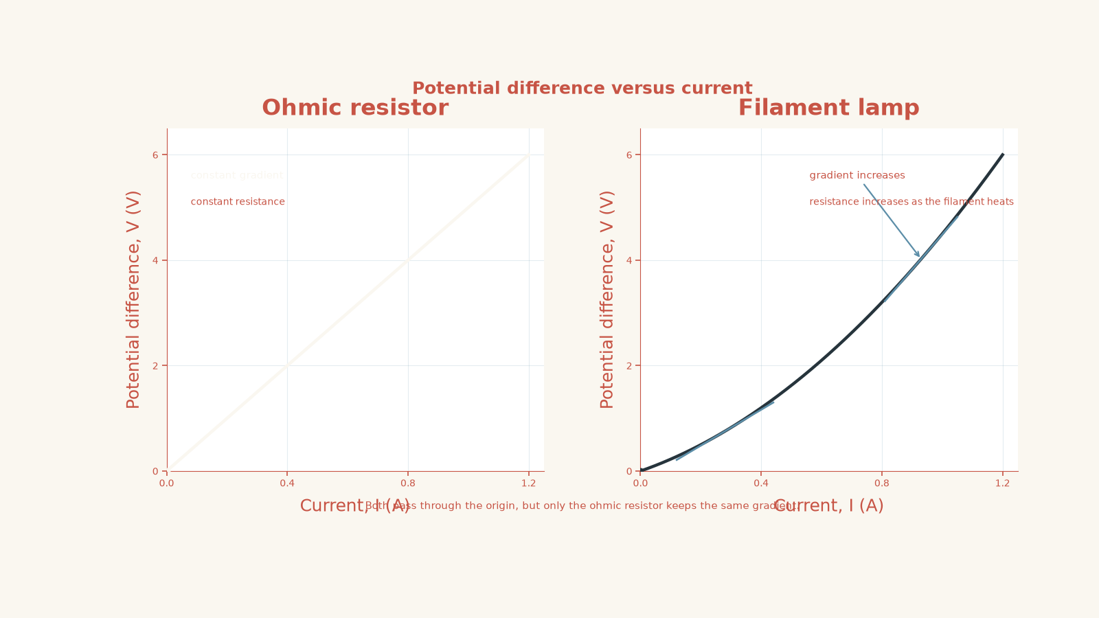
Be careful with the axes. The gradient depends on which variable is vertical.
| Graph | Gradient |
|---|---|
| \(V\) on vertical axis, \(I\) on horizontal axis | \(R\) |
| \(I\) on vertical axis, \(V\) on horizontal axis | \(1/R\) |
For a \(V\)-against-\(I\) graph,
\[ R = \frac{\Delta V}{\Delta I} \]
for an ohmic resistor because the graph is linear.
A steeper line therefore means a larger resistance.
For a filament lamp, the \(V\)-against-\(I\) graph becomes steeper as current rises. That matches the physical explanation: the filament gets hotter, and its resistance increases.
06The most tempting misconceptions
“If I can use \(V = IR\), the component must be ohmic”
No.
At one operating point, \(R = V/I\) can still describe the component’s resistance at that point.
To establish ohmic behaviour, you need evidence that \(V/I\) stays constant as the operating point changes.
“A straight graph automatically means the component is ohmic”
Not quite.
For direct proportionality, the graph must be a straight line through the origin.
Suppose a device follows
\[ V = 1.0 + 3.0I \]
with \(V\) in volts and \(I\) in amperes.
That is a straight line, but
\[ \frac{V}{I} = \frac{1.0 + 3.0I}{I} = \frac{1.0}{I} + 3.0 \]
which changes with current.
So \(V\) is not directly proportional to \(I\), and the device does not obey Ohm’s law over that range.
“Resistance belongs permanently to the object”
A quoted resistance is only meaningful under specified conditions.
A metal resistor may be close enough to constant over the range used in a school circuit that treating \(R\) as fixed is a very good model. A hot filament makes the limitation obvious because its temperature changes dramatically.
For more detail on interpreting these behaviours, see ohmic and non-ohmic conductors.
07A practical test for whether constant \(R\) is justified
When you see a new HSC question, don’t immediately reach for \(V = IR\) and substitute numbers. Check what the question is actually telling you.
Ask:
- Is the component explicitly described as ohmic?
- Is a fixed resistance given?
- Are the physical conditions reasonably constant?
- Does experimental data show \(V/I\) remaining constant?
- Does a graph show direct proportionality between \(V\) and \(I\)?
- Could heating or another changing condition alter the resistance?
If \(R\) is constant, then changing \(V\) changes \(I\) proportionally.
If \(R\) changes, one resistance value cannot safely be carried from one operating point to another.
08Questions and solutions
Question 1
A \(24\ \Omega\) resistor is connected across a 12 V supply. The resistor is ohmic and its temperature remains effectively constant. Calculate the current.
Solution 1
The current is \(0.50\ \mathrm{A}\).
Because the resistor is ohmic and its physical conditions are constant, its resistance can be treated as fixed.
Using
\[ V = IR \]
and rearranging,
\[ I = \frac{V}{R} \]
Substitute:
\[ I = \frac{12\ \mathrm{V}}{24\ \Omega} = 0.50\ \mathrm{A} \]
So \(0.50\ \mathrm{C}\) of charge passes a point in the circuit each second.
Question 2
A student measures the following values for a component:
| Potential difference \(V\) | Current \(I\) |
|---|---|
| 2.0 V | 0.40 A |
| 4.0 V | 0.80 A |
| 6.0 V | 1.20 A |
Determine whether the data are consistent with an ohmic conductor. If the same behaviour continues, predict the current at 9.0 V.
Solution 2
The data are consistent with an ohmic conductor with resistance \(5.0\ \Omega\), and the predicted current at 9.0 V is \(1.8\ \mathrm{A}\).
Check the resistance at each operating point:
\[ R_1 = \frac{2.0\ \mathrm{V}}{0.40\ \mathrm{A}} = 5.0\ \Omega \]
\[ R_2 = \frac{4.0\ \mathrm{V}}{0.80\ \mathrm{A}} = 5.0\ \Omega \]
\[ R_3 = \frac{6.0\ \mathrm{V}}{1.20\ \mathrm{A}} = 5.0\ \Omega \]
The ratio \(V/I\) is constant, so the measurements show direct proportionality between voltage and current.
Using the same resistance at 9.0 V,
\[ I = \frac{V}{R} = \frac{9.0\ \mathrm{V}}{5.0\ \Omega} = 1.8\ \mathrm{A} \]
The prediction relies on the assumption that the component remains under the same physical conditions at 9.0 V.
Question 3
A lamp carries \(0.50\ \mathrm{A}\) when the potential difference across it is 2.0 V. At 6.0 V, it carries \(1.0\ \mathrm{A}\).
A student says, “The lamp doesn’t obey \(V = IR\), because its resistance changed.”
Evaluate this statement using the measurements.
Solution 3
The student’s conclusion is incorrect: the lamp is non-ohmic, but \(R = V/I\) can still describe its resistance at each operating point.
At 2.0 V,
\[ R = \frac{V}{I} = \frac{2.0\ \mathrm{V}}{0.50\ \mathrm{A}} = 4.0\ \Omega \]
At 6.0 V,
\[ R = \frac{6.0\ \mathrm{V}}{1.0\ \mathrm{A}} = 6.0\ \Omega \]
The resistance has changed from \(4.0\ \Omega\) to \(6.0\ \Omega\).
The real issue is that Ohm’s law requires constant resistance under constant physical conditions. Here, the ratio \(V/I\) changes as the operating point changes.
A likely cause is heating of the lamp’s metal filament. Its higher temperature increases its resistance.
The tempting mistake is to interpret “non-ohmic” as meaning that voltage, current, and resistance no longer have any relationship. They do. What fails is the assumption of a single constant \(R\).
Question 4
A black-box electrical component produces these measurements:
| Potential difference \(V\) | Current \(I\) |
|---|---|
| 2.0 V | 0.25 A |
| 4.0 V | 0.50 A |
| 6.0 V | 0.60 A |
After taking the first two measurements, a student concludes that the component obeys Ohm’s law.
Explain why that conclusion was reasonable at the time, but is no longer supported by all three measurements.
Solution 4
The first two measurements suggest an \(8.0\ \Omega\) ohmic component, but the third measurement shows that the resistance is not constant across the full tested range.
For the first point,
\[ R_1 = \frac{2.0\ \mathrm{V}}{0.25\ \mathrm{A}} = 8.0\ \Omega \]
For the second,
\[ R_2 = \frac{4.0\ \mathrm{V}}{0.50\ \mathrm{A}} = 8.0\ \Omega \]
Those two measurements are consistent with direct proportionality, so the student’s early conclusion was reasonable evidence-based reasoning.
However, for the third point,
\[ R_3 = \frac{6.0\ \mathrm{V}}{0.60\ \mathrm{A}} = 10\ \Omega \]
The resistance has increased.
Therefore the full set of data does not support a constant-resistance model across 2.0 V to 6.0 V.
This also shows why one or two convenient data points aren’t enough to establish a physical relationship confidently. A component may behave approximately ohmically over a limited range and then depart from that model when its conditions change.
Question 5
A component produces a perfectly straight \(V\)-against-\(I\) graph described by
\[ V = 0.80 + 4.0I \]
where \(V\) is measured in volts and \(I\) in amperes.
A student argues that the component must obey Ohm’s law because the graph is straight.
Is the student correct? Support your conclusion by comparing the resistance at \(I = 0.20\ \mathrm{A}\) and \(I = 0.60\ \mathrm{A}\).
Solution 5
No. A straight graph alone is not enough: an ohmic conductor requires direct proportionality, so its \(V\)-against-\(I\) graph must pass through the origin.
At \(I = 0.20\ \mathrm{A}\),
\[ V = 0.80 + 4.0(0.20) = 1.60\ \mathrm{V} \]
so
\[ R = \frac{V}{I} = \frac{1.60\ \mathrm{V}}{0.20\ \mathrm{A}} = 8.0\ \Omega \]
At \(I = 0.60\ \mathrm{A}\),
\[ V = 0.80 + 4.0(0.60) = 3.20\ \mathrm{V} \]
so
\[ R = \frac{3.20\ \mathrm{V}}{0.60\ \mathrm{A}} \approx 5.3\ \Omega \]
The resistance is not constant.
The trap is confusing a linear relationship with direct proportionality. Direct proportionality requires both a straight line and passage through the origin.
09Where this takes you next
Ohm’s law gives you a model for how voltage and current are connected when resistance stays constant. The next step is knowing when the material or component itself changes that resistance.
Once you can look at a table, graph, or physical situation and decide whether \(R\) should be treated as constant, circuit questions become much less mechanical. You’re no longer just choosing an equation. You’re deciding whether the model behind the equation actually fits the device.