
Double-Slit Interference and Fringe Evidence for HSC Physics
Learn how double-slit interference creates bright and dark fringes, and use fringe evidence with d sin theta = m lambda. Includes worked examples, common misconceptions, and challenging HSC-style questions.
Shine a laser at two narrow slits and put a screen behind them. What should appear? If you picture light as tiny projectiles travelling straight through each opening, two bright bands seem like the sensible prediction.
That is not what you get. You get a row of bright and dark fringes.
The dark fringes are the strange part. Opening a second slit can make some places on the screen receive less light than when only one slit is open. Any model of light has to explain that.
01What creates the bright and dark fringes?
Each narrow slit spreads the incoming light out. This spreading is diffraction, and it lets light from the two slits overlap across the screen.
At any point where the two waves overlap, their electric fields add.
Before going further, predict what happens at the exact centre of the screen. The point is the same distance from both slits, so the two waves travel equal distances. If the slits are illuminated in phase, the waves arrive in phase as well. Their crests line up with crests, their troughs line up with troughs, and the centre is bright.
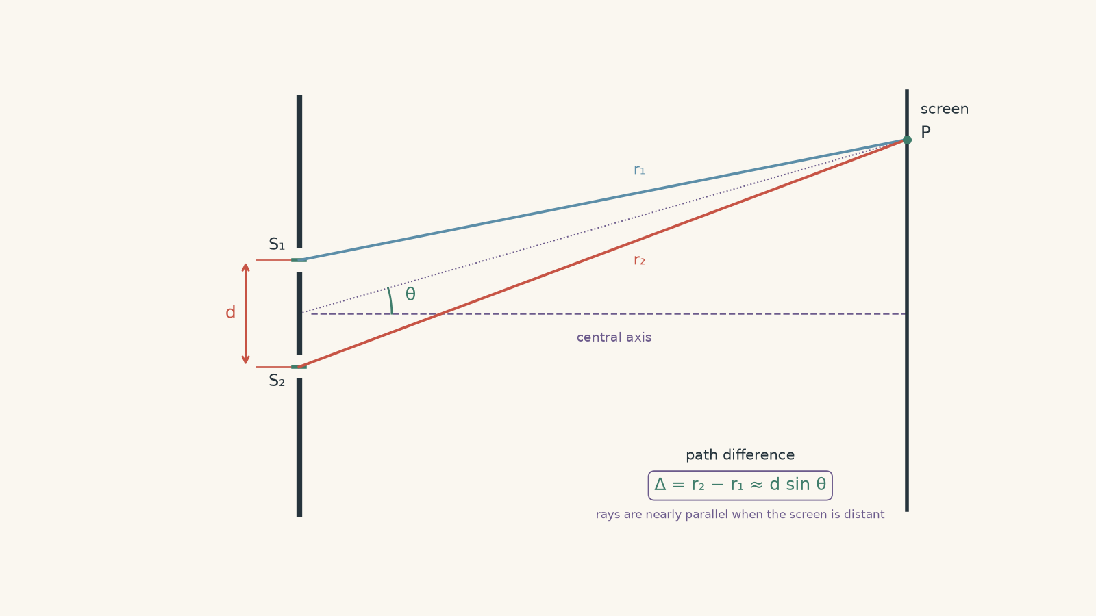
Move slightly sideways, though, and one slit becomes farther from the observation point than the other. One wave now travels an extra distance.
That extra distance is the path difference.
A useful way to picture the addition is two people pushing a swing. If both push at the same stage of the swing, their effects reinforce. If one pushes exactly when the other would pull the opposite way, their effects oppose.
For light, the “pushes” are oscillating electric fields. The analogy stops there: light is not a physical swing, and its intensity depends on the square of the resulting wave amplitude.
The important pattern is:
| Path difference \(\Delta\) | How the waves arrive | Result |
|---|---|---|
| \(0\) | In phase | Bright |
| \(\lambda\) | In phase again | Bright |
| \(2\lambda\) | In phase again | Bright |
| \(\frac{1}{2}\lambda\) | Opposite phase | Dark |
| \(\frac{3}{2}\lambda\) | Opposite phase | Dark |
| Anything between these | Partly reinforcing or cancelling | Intermediate intensity |
Here, \(\lambda\) is the wavelength of the light.
This immediately explains why a whole sequence of fringes appears. As you move across the screen, the path difference gradually changes. The waves repeatedly move from reinforcing, to cancelling, to reinforcing again.
02Turning path difference into \(d\sin\theta=m\lambda\)
The idea above tells us why fringes occur. Now we need a way to predict exactly where the bright ones will be.
Let:
| Symbol | Meaning |
|---|---|
| \(d\) | separation between the two slits, in metres |
| \(\theta\) | angle from the central axis to a fringe |
| \(\lambda\) | wavelength of the light, in metres |
| \(m\) | fringe order: \(0,\pm1,\pm2,\ldots\) |
When the screen is far from the slits compared with the slit separation, the two rays travelling towards one point are nearly parallel. The geometry then gives the path difference
\[
\Delta=d\sin\theta
\]
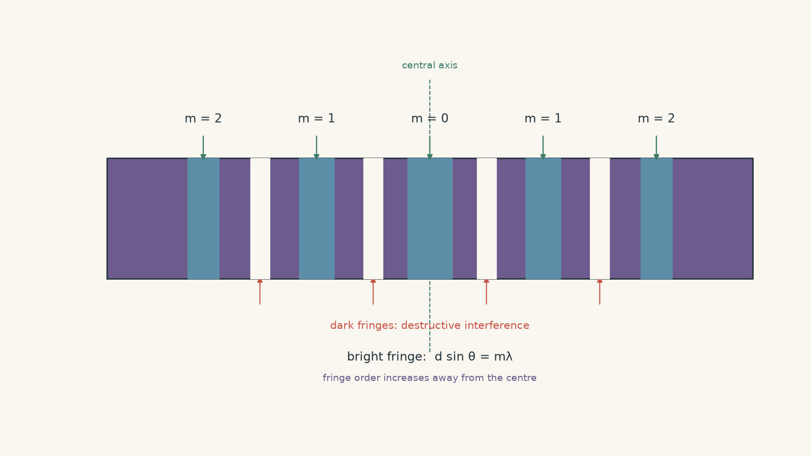
A bright fringe occurs when the path difference is a whole number of wavelengths:
\[
\Delta=m\lambda
\]
Combining these gives the double-slit interference equation used for bright fringes:
\[
d\sin\theta=m\lambda
\]
The central maximum has \(m=0\). The first bright fringe on either side has \(|m|=1\), the second has \(|m|=2\), and so on.
Notice what \(m\) is doing. It is not a distance, and it is not measured in metres. It simply counts how many whole wavelengths fit into the path difference.
For a dark fringe, the waves need to arrive half a cycle out of step. On one side of the centre,
\[
d\sin\theta=\left(m+\frac{1}{2}\right)\lambda
\]
where \(m=0,1,2,\ldots\).
Worked example: Finding the angle of a bright fringe
A laser of wavelength \(600\text{ nm}\) shines through two slits separated by \(0.250\text{ mm}\). Calculate the angle between the central axis and the first-order bright fringe.
Step 1
The first-order maximum has \(m=1\), so
\[
d\sin\theta=m\lambda
\]
Step 2
\[
\lambda=600\text{ nm}=600\times10^{-9}\text{ m}
\]
\[
d=0.250\text{ mm}=2.50\times10^{-4}\text{ m}
\]
Step 3
\[
\begin{aligned}
(2.50\times10^{-4})\sin\theta
&=(1)(600\times10^{-9})\\
\sin\theta
&=2.40\times10^{-3}\\
\theta
&=\sin^{-1}(2.40\times10^{-3})\\
&=0.138^\circ
\end{aligned}
\]
Step 4
The first bright fringe is only \(0.138^\circ\) away from the central axis. That small angle is normal because optical wavelengths are tiny compared with typical slit separations.
03Connecting the angle to a position on the screen
Exam questions will sometimes give the distance from the slits to the screen rather than the fringe angle.
If the screen is a perpendicular distance \(L\) from the slits and a fringe is a distance \(y\) from the centre, then ordinary right-triangle geometry gives
\[
\tan\theta=\frac{y}{L}
\]
You can first find \(\theta\), then use \(d\sin\theta=m\lambda\).
For very small angles, \(\sin\theta\) and \(\tan\theta\) are almost equal when \(\theta\) is measured in radians. This leads to the familiar approximation
\[
y\approx\frac{m\lambda L}{d}
\]
It is useful, but it is an approximation. If the question gives enough information to find the angle directly, using the trigonometric relationships keeps the reasoning clearer.
Worked example: Using measured fringes to find wavelength
Two slits are separated by \(0.200\text{ mm}\). A screen is \(2.00\text{ m}\) away. The second-order bright fringe is measured \(12.0\text{ mm}\) from the centre. Find the wavelength of the light.
Step 1
Here,
\[
y=12.0\text{ mm}=0.0120\text{ m}
\]
and
\[
L=2.00\text{ m}
\]
so
\[
\begin{aligned}
\tan\theta&=\frac{0.0120}{2.00}\\
\theta&=\tan^{-1}(0.00600)\\
&=0.3438^\circ
\end{aligned}
\]
Step 2
The question says this is the second-order bright fringe, so \(m=2\).
Step 3
\[
\lambda=\frac{d\sin\theta}{m}
\]
with
\[
d=0.200\text{ mm}=2.00\times10^{-4}\text{ m}
\]
Therefore,
\[
\begin{aligned}
\lambda
&=\frac{(2.00\times10^{-4})\sin(0.3438^\circ)}{2}\\
&=6.00\times10^{-7}\text{ m}\\
&=600\text{ nm}
\end{aligned}
\]
Step 4
The measured fringe positions imply a wavelength of about \(600\text{ nm}\). This is why interference is more than a pretty pattern: the fringe geometry can be used to measure a physical property of the light.
04What the fringes are evidence for
Simply seeing light spread out after two slits is not strong evidence for interference. Each individual slit already causes diffraction.
The stronger evidence is the organised sequence of bright and dark regions.
At a dark fringe, light from either slit by itself could reach that point. Yet when both coherent contributions arrive together with the right phase difference, their fields cancel. A simple picture of two independent streams of light cannot account for that alternating cancellation and reinforcement.
The wave model predicts more than the existence of fringes. It predicts their angles:
\[
d\sin\theta=m\lambda
\]
Change the wavelength, and the angles change. Change the slit separation, and the angles change again. Measurements can then be checked against those predictions.
That agreement between a quantitative prediction and the observed pattern is the important evidence.
There is another piece of the experiment hiding underneath this. The light from each slit must spread enough for the two contributions to overlap. That is why diffraction of light and double-slit interference are connected. A real double-slit pattern is usually a set of interference fringes sitting inside a broader diffraction envelope.
05What changes the fringe spacing?
The equation gives a useful way to reason before touching a calculator.
For a particular order \(m\),
\[
\sin\theta=\frac{m\lambda}{d}
\]
A larger wavelength therefore gives a larger fringe angle. The pattern spreads out.
A larger slit separation does the opposite. It reduces the angle needed to produce the same path difference, so the fringes move closer together.
That second result catches people. It is tempting to think that moving the slits farther apart should move the fringes farther apart too. But the screen pattern is controlled by path difference, not by simply copying the physical spacing of the slits onto the screen.
There is also a hard limit hidden inside the sine function. Because
\[
|\sin\theta|\leq1
\]
a bright order can only exist if
\[
|m|\lambda\leq d
\]
So the equation does not guarantee infinitely many observable orders.
06The assumptions hiding inside the formula
The familiar expression
\[
d\sin\theta=m\lambda
\]
is not a magic rule that works whenever two slits exist.
It assumes the waves leaving the slits have a fixed relative phase and, in the standard Young double-slit arrangement, are effectively in phase with each other. This is normally achieved by illuminating both slits with the same coherent source.
Coherent sources maintain a stable phase relationship.
Why does that matter? Suppose the relative phase wandered randomly. A point on the screen might be bright at one moment and dark at another. Over a long exposure, the stable interference pattern could wash out.
There is another subtle assumption. If one slit is deliberately given a fixed half-cycle phase shift before the light leaves it, equal path lengths no longer produce constructive interference. The centre can become dark even though the geometrical path difference is zero.
That does not mean interference has failed. It means path difference is only one contribution to the total phase difference.
07Common wrong turns
| Tempting idea | What actually matters |
|---|---|
| “Two slits should produce two bright lines.” | Each slit diffracts, so the waves overlap and interfere across the screen. |
| “The centre is bright because it is closest to the slits.” | It is bright because the two path lengths are equal, giving zero path difference for in-phase slits. |
| “The first bright fringe I notice must be \(m=1\).” | Some fringes may be hidden, weak, or outside the measured region. The order must be justified. |
| “A larger \(d\) gives wider fringe spacing.” | Since \(\sin\theta=m\lambda/d\), increasing \(d\) brings the angular fringes closer together. |
| “\(d\sin\theta=m\lambda\) works for every point.” | It gives constructive-interference positions for the standard in-phase double-slit arrangement. |
| “A dark fringe means neither slit sends light there.” | Each slit can contribute light there individually. Darkness results from destructive superposition of the two waves. |
08Questions and solutions
Question 1
A \(600\text{ nm}\) laser illuminates two narrow slits separated by \(0.300\text{ mm}\). Calculate the angle from the central axis to the first-order bright fringe.
Solution 1
The first-order bright fringe is at approximately \(0.115^\circ\) from the central axis.
For a bright fringe,
\[
d\sin\theta=m\lambda
\]
Here,
\[
d=0.300\text{ mm}=3.00\times10^{-4}\text{ m}
\]
\[
\lambda=600\text{ nm}=6.00\times10^{-7}\text{ m}
\]
and \(m=1\). Therefore,
\[
\begin{aligned}
\sin\theta
&=\frac{(1)(6.00\times10^{-7})}{3.00\times10^{-4}}\\
&=2.00\times10^{-3}\\
\theta
&=\sin^{-1}(2.00\times10^{-3})\\
&=0.1146^\circ
\end{aligned}
\]
So,
\[
\theta\approx0.115^\circ
\]
A common mistake is to divide \(600\) by \(0.300\) without first putting the wavelength and slit separation into compatible units. The equation compares two lengths, so their units must be consistent.
Question 2
Two slits are separated by \(0.250\text{ mm}\), and a screen is \(1.80\text{ m}\) away. The third-order bright fringe is \(11.23\text{ mm}\) from the centre.
Calculate the wavelength of the light, then find the position of the next dark fringe farther from the centre.
Solution 2
The wavelength is approximately \(520\text{ nm}\), and the next dark fringe is about \(13.1\text{ mm}\) from the centre.
First find the angle to the third-order maximum:
\[
\begin{aligned}
\tan\theta
&=\frac{0.01123}{1.80}\\
\theta
&\approx0.3575^\circ
\end{aligned}
\]
For the third-order bright fringe, \(m=3\), so
\[
\lambda=\frac{d\sin\theta}{m}
\]
with
\[
d=0.250\text{ mm}=2.50\times10^{-4}\text{ m}
\]
Therefore,
\[
\begin{aligned}
\lambda
&=\frac{(2.50\times10^{-4})\sin(0.3575^\circ)}{3}\\
&\approx5.20\times10^{-7}\text{ m}\\
&=520\text{ nm}
\end{aligned}
\]
Now consider the next dark fringe farther from the centre.
The third bright fringe has path difference \(3\lambda\). The next destructive condition occurs at
\[
\Delta=3.5\lambda
\]
so
\[
d\sin\theta_{\text{dark}}=3.5\lambda
\]
Hence,
\[
\begin{aligned}
\sin\theta_{\text{dark}}
&=\frac{3.5(520\times10^{-9})}{2.50\times10^{-4}}\\
\theta_{\text{dark}}
&\approx0.4171^\circ
\end{aligned}
\]
The screen position is
\[
\begin{aligned}
y
&=L\tan\theta_{\text{dark}}\\
&=(1.80)\tan(0.4171^\circ)\\
&=1.31\times10^{-2}\text{ m}\\
&=13.1\text{ mm}
\end{aligned}
\]
The tempting mistake is to use \(m=4\) for the next dark fringe. Integer orders describe bright fringes. The dark fringe between the third and fourth maxima occurs at a path difference of \(3.5\lambda\).
Question 3
Experiment A uses light of wavelength \(450\text{ nm}\) and slit separation \(0.300\text{ mm}\).
Experiment B uses a different monochromatic light source and slit separation \(0.400\text{ mm}\). The bright fringes in experiment B occur at exactly the same angles as the corresponding bright fringes in experiment A.
Determine the wavelength used in experiment B. Then explain why observing the same angular fringe pattern does not, by itself, prove that two sources have the same wavelength.
Solution 3
Experiment B uses light of wavelength \(600\text{ nm}\), and identical angular fringe positions do not uniquely determine wavelength unless the slit separation is also known.
For a given order,
\[
\sin\theta=\frac{m\lambda}{d}
\]
If every corresponding order occurs at the same angle, then the ratio \(\lambda/d\) must be the same in both experiments:
\[
\frac{\lambda_A}{d_A}=\frac{\lambda_B}{d_B}
\]
Substituting,
\[
\frac{450\times10^{-9}}{0.300\times10^{-3}}
=
\frac{\lambda_B}{0.400\times10^{-3}}
\]
Therefore,
\[
\begin{aligned}
\lambda_B
&=(0.400\times10^{-3})
\frac{450\times10^{-9}}{0.300\times10^{-3}}\\
&=600\times10^{-9}\text{ m}\\
&=600\text{ nm}
\end{aligned}
\]
The key point is that the interference angles depend on the ratio
\[
\frac{\lambda}{d}
\]
rather than on \(\lambda\) alone.
The tempting conclusion is that matching patterns mean matching wavelengths. That would only follow if the slit separations were also identical. Here, both the wavelength and slit separation increased by the same factor, so their ratio stayed unchanged.
This is an important point about experimental evidence: a pattern supports a model through the quantities the model actually relates. You need enough independent measurements to determine the unknown quantity uniquely.
Question 4
A monochromatic visible source passes through two slits separated by \(0.400\text{ mm}\). A detector records bright interference peaks at angles for which
\[
\sin\theta=0.0030,\qquad 0.0045,\qquad 0.0075
\]
Some other parts of the detector are blocked, so these are not necessarily consecutive fringe orders.
The wavelength is known to lie between \(400\text{ nm}\) and \(700\text{ nm}\).
Determine the wavelength and the order \(m\) of each recorded peak. Then predict the angles of the two missing maxima that lie between the centre and the largest-angle recorded peak.
Solution 4
The wavelength is \(600\text{ nm}\); the recorded peaks are \(m=2\), \(m=3\), and \(m=5\). The missing maxima are \(m=1\) at about \(0.0859^\circ\) and \(m=4\) at about \(0.3438^\circ\).
Instead of immediately calling the first recorded peak \(m=1\), calculate the path difference corresponding to each measurement:
\[
\Delta=d\sin\theta
\]
Using
\[
d=0.400\text{ mm}=4.00\times10^{-4}\text{ m}
\]
gives
\[
\begin{aligned}
\Delta_1
&=(4.00\times10^{-4})(0.0030)
=1.20\times10^{-6}\text{ m}
=1200\text{ nm}\\
\Delta_2
&=(4.00\times10^{-4})(0.0045)
=1800\text{ nm}\\
\Delta_3
&=(4.00\times10^{-4})(0.0075)
=3000\text{ nm}
\end{aligned}
\]
Each bright fringe must satisfy
\[
\Delta=m\lambda
\]
so the same visible wavelength must divide all three path differences into whole-number orders.
A wavelength of \(600\text{ nm}\) gives
\[
1200\text{ nm}=2(600\text{ nm})
\]
\[
1800\text{ nm}=3(600\text{ nm})
\]
\[
3000\text{ nm}=5(600\text{ nm})
\]
Therefore the recorded peaks have orders \(2\), \(3\), and \(5\).
The \(m=1\) maximum satisfies
\[
\begin{aligned}
\sin\theta_1
&=\frac{600\times10^{-9}}{4.00\times10^{-4}}\\
&=0.0015
\end{aligned}
\]
so
\[
\theta_1=\sin^{-1}(0.0015)\approx0.0859^\circ
\]
The missing \(m=4\) maximum satisfies
\[
\begin{aligned}
\sin\theta_4
&=\frac{4(600\times10^{-9})}{4.00\times10^{-4}}\\
&=0.0060
\end{aligned}
\]
so
\[
\theta_4\approx0.3438^\circ
\]
The tempting route is to assume the first observed peak must be \(m=1\). That would imply
\[
\lambda=1200\text{ nm}
\]
which is already outside the stated visible range. More importantly, assigning orders must make all of the observations consistent with one wavelength. The missing-fringe information means observation order and fringe order are not the same thing.
Question 5
A double-slit apparatus has slit separation \(d=0.250\text{ mm}\) and uses light of wavelength \(500\text{ nm}\). The two slits receive equal-amplitude coherent waves.
In setup A, the waves reaching the two slits are in phase.
In setup B, one slit receives a wave that has been given a fixed half-cycle phase shift relative to the other slit.
In setup C, the apparatus rapidly switches between the phase relationship of setup A and the phase relationship of setup B, spending equal time in each state. The detector records only the time-averaged intensity.
For each setup, determine what happens on the central axis. For setup B, calculate the angle of the nearest bright fringe. Finally, determine whether setup C produces a stable set of fine interference fringes in the time-averaged image. Assume ideal equal slit intensities and ignore the broad diffraction envelope when discussing the fine fringes.
Solution 5
Setup A has a bright central fringe; setup B has a dark centre and its nearest bright fringe is at about \(0.0573^\circ\); setup C has no stable fine interference fringes in the time-averaged image.
For setup A, the two slits are illuminated in phase. On the central axis, both paths have the same length, so
\[
\Delta=0
\]
The waves therefore arrive with zero total phase difference and interfere constructively. This is the ordinary \(m=0\) central maximum.
For setup B, the geometrical path difference on the central axis is still zero. However, one wave already starts half a cycle out of phase with the other.
Equal path lengths therefore preserve that half-cycle difference. The central point is now a destructive-interference position.
To turn that initial half-cycle mismatch into constructive interference, the path difference must add another half wavelength. The nearest bright fringe therefore satisfies
\[
d\sin\theta=\frac{\lambda}{2}
\]
Substituting
\[
d=2.50\times10^{-4}\text{ m}
\]
and
\[
\lambda=5.00\times10^{-7}\text{ m}
\]
gives
\[
\begin{aligned}
\sin\theta
&=\frac{5.00\times10^{-7}}
{2(2.50\times10^{-4})}\\
&=1.00\times10^{-3}\\
\theta
&=\sin^{-1}(1.00\times10^{-3})\\
&\approx0.0573^\circ
\end{aligned}
\]
So the pattern in setup B is shifted: positions that were maxima in setup A become minima, and the new maxima lie halfway between the original ones.
Setup C is subtler.
For half of the exposure, the detector receives the ordinary pattern from setup A. For the other half, it receives the shifted pattern from setup B. With equal slit intensities, the second pattern is complementary to the first: where the interference contribution raises the intensity in one state, it lowers it by the corresponding amount in the other.
Averaging the two equally removes the angle-dependent interference contribution. The detector therefore does not record stable fine bright and dark fringes. If the finite width of the individual slits were included, the broader single-slit diffraction envelope could still remain.
The tempting argument is that \(d\) and \(\lambda\) never changed, so
\[
d\sin\theta=m\lambda
\]
should force the same pattern in all three setups.
The missing constraint is the relative phase of the waves before the extra path difference is introduced. The standard equation assumes the usual in-phase double-slit arrangement. Interference depends on total phase difference, not on geometrical path difference alone.
That is the deeper lesson of the double-slit experiment: the fringe pattern does not come from the slits simply pointing light towards certain locations. It comes from coherent wave contributions combining at each location.
09What this idea unlocks next
Once you can read a double-slit pattern in terms of path difference, interference stops being something you identify by appearance alone. You can use fringe positions to infer wavelength, test whether measurements fit a wave model, predict how an apparatus change will alter the pattern, and recognise when the standard formula’s assumptions have been broken.
The next useful step is to connect that interference pattern with the diffraction produced by each individual slit. The two effects occur together: diffraction determines where light from each slit can spread, while interference determines how the overlapping contributions reinforce and cancel inside that region.