
Reflection and Image Formation in Mirrors for HSC Physics
Learn how ray diagrams locate and describe images formed by plane, concave, and convex mirrors. Includes worked examples, common misconceptions, and original HSC-style practice.
A flat bathroom mirror, a curved makeup mirror, and a car’s side mirror all obey the same law of reflection, yet they can produce images that are the same size, larger, smaller, upright, or upside down. So what is the mirror actually doing differently?
Before reading on, predict this: if reflected light rays spread apart after leaving a mirror, can they still form an image? It seems like the answer should be no because the rays never meet. But your eyes can trace those rays backwards and make them appear to come from one point. That is the key to understanding virtual images.
01What a ray diagram is actually trying to find
Suppose light leaves the top of an object and hits a mirror. One ray is not enough to tell you where the image is. You need to follow at least two rays from the same point on the object and see what happens after reflection.
There are two possibilities:
- The reflected rays actually meet. The meeting point is a real image.
- The reflected rays spread apart, but their backward extensions meet. That apparent meeting point is a virtual image.
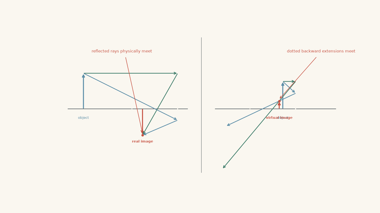
Think of your eye as doing a bit of detective work. It receives a reflected ray and assumes the light travelled towards it in a straight line. It mentally traces that ray backwards. If several reflected rays seem to have come from the same place, that is where you see the image.
The analogy has a limit. Your brain is not literally drawing dotted construction lines. The ray diagram is a model that predicts the apparent origin of the light.
Real versus virtual images
This distinction matters because only a real image can be projected directly onto a screen.
If reflected rays physically arrive at a piece of paper placed at the image position, the light can form a visible pattern there. If the image is virtual, there is no light actually travelling through the apparent image position, so putting a screen there will not capture it.
That gives you a useful test:
| Image type | Do reflected rays really meet there? | Can it be projected onto a screen? |
|---|---|---|
| Real | Yes | Yes |
| Virtual | No | No |
02Start with the law of reflection
Every mirror ray diagram comes from one rule:
\[ \theta_i = \theta_r \]
where \(\theta_i\) is the angle of incidence and \(\theta_r\) is the angle of reflection.
Both angles are measured from the normal, not from the mirror surface.
The normal is an imaginary line drawn perpendicular to the mirror at the point where the ray hits.
A common mistake is to measure the angles from the mirror itself. If a ray makes \(20^\circ\) with the mirror surface, for example, it makes \(70^\circ\) with the normal. Its angle of incidence is therefore \(70^\circ\), not \(20^\circ\).
03Plane mirrors: why the image appears behind the glass
Stand in front of a flat mirror and look at your reflection. Light from your face travels towards the mirror, reflects, and enters your eyes.
The reflected light is travelling away from the mirror. There is no version of you physically sitting behind the glass.
Yet your eye traces those reflected rays backwards. Their backward extensions intersect behind the mirror, so that is where the image appears to be.
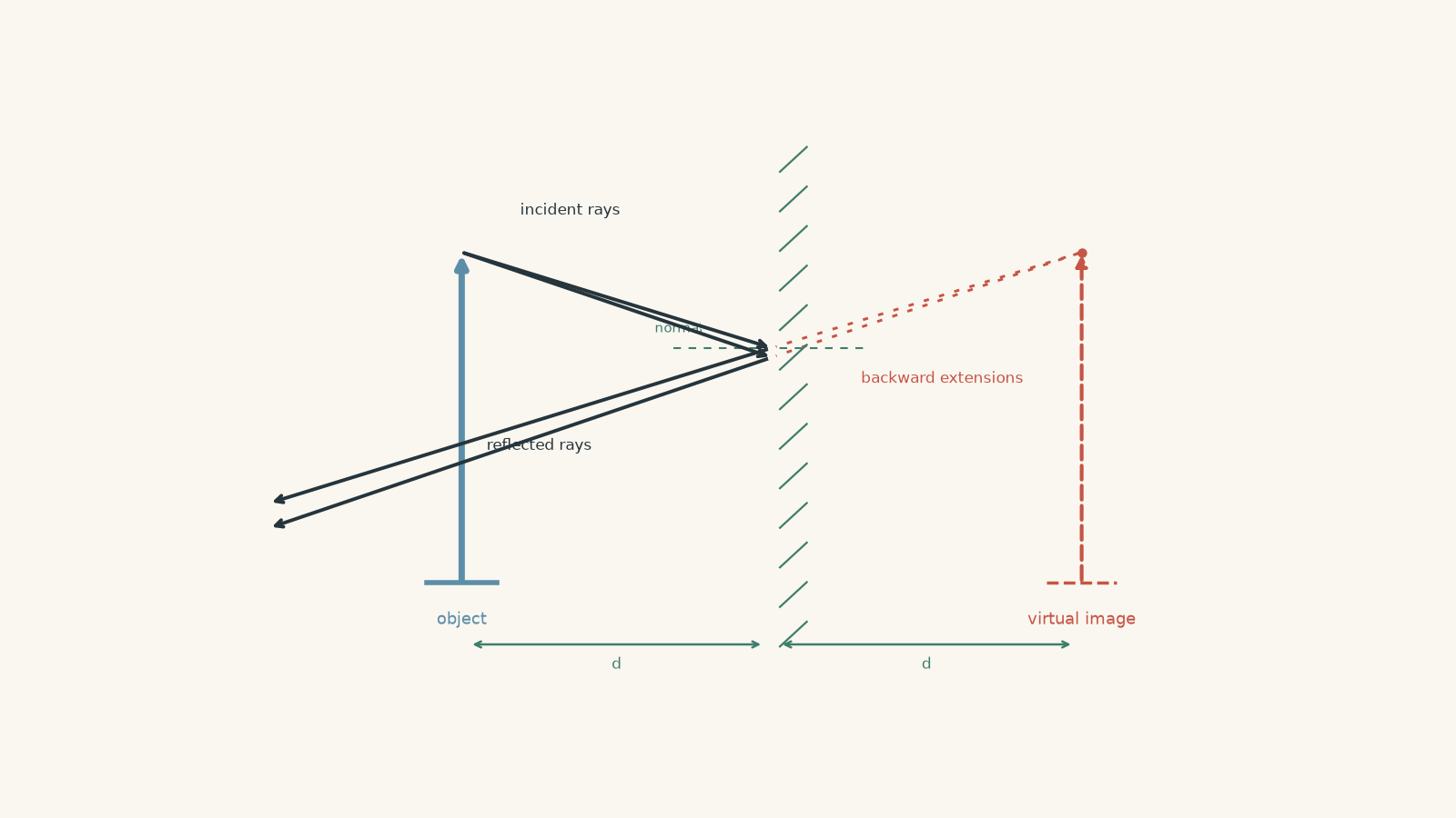
For a plane mirror, the image is:
- the same size as the object
- upright
- virtual
- the same perpendicular distance behind the mirror as the object is in front
It is also laterally inverted. If you raise your right hand, the image appears to raise the hand on the opposite side of the image.
More precisely, the mirror reverses the direction perpendicular to its surface. The familiar “left-right reversal” description comes from how we compare ourselves with an image that appears to face us.
Worked example: locating an image in a plane mirror
A student stands \(0.80\ \text{m}\) in front of a plane mirror. Where is the image, and how far is the student from the image?
Step 1
The image is the same distance behind the mirror as the object is in front.
So the image is \(0.80\ \text{m}\) behind the mirror.
Step 2
The student is \(0.80\ \text{m}\) in front of the mirror, and the image is \(0.80\ \text{m}\) behind it.
\[ \text{separation} = 0.80\ \text{m} + 0.80\ \text{m} = 1.60\ \text{m} \]
Step 3
The image is virtual, upright, and the same size as the student.
The important point is that the \(1.60\ \text{m}\) separation is not a distance that light travels directly from the student to an object behind the mirror. Part of that distance is an apparent position produced by extending the reflected rays backwards.
04Curved mirrors change where reflected rays travel
A plane mirror has the same orientation everywhere. A curved mirror does not.
That means two parallel rays can strike different parts of the mirror where the normals point in different directions. The rays still obey \(\theta_i=\theta_r\), but they leave in different directions.
This is how a curved mirror can make rays converge or diverge.
There are two important types.
A concave mirror curves inward on the reflecting side, like the inside of a spoon.
A convex mirror bulges outward towards the object, like the back of a spoon.
For spherical mirrors, we use several reference points:
- the principal axis is the straight line through the centre of the mirror
- the vertex is where the principal axis meets the mirror
- the centre of curvature, \(C\), is the centre of the sphere from which the mirror surface could have been cut
- the focal point, \(F\), is the point associated with rays travelling parallel to the principal axis
- the focal length, \(f\), is the distance from the vertex to \(F\)
For a spherical mirror using rays close to the principal axis,
\[ f \approx \frac{R}{2} \]
where \(R\) is the radius of curvature.
The phrase “rays close to the principal axis” matters. A perfectly spherical mirror does not bring every widely separated parallel ray to exactly the same point. The standard HSC ray model uses paraxial rays, meaning rays reasonably close to the principal axis.
05The principal rays for a concave mirror
You could apply the law of reflection separately at every point on a curved mirror. That would work, but it would be painfully slow.
Instead, ray diagrams use a few rays whose paths are easy to predict.
For a concave mirror:
| Incident ray | Reflected ray |
|---|---|
| Parallel to the principal axis | Passes through \(F\) |
| Passes through \(F\) | Travels parallel to the principal axis |
| Passes through \(C\) | Returns along the same path |
The ray through \(C\) returns along itself because it strikes the spherical surface along a radius. The radius is normal to the surface, so the angle of incidence is \(0^\circ\).
You normally only need two of these rays to locate an image. A third ray is useful as a check.
06How to draw a concave-mirror ray diagram
Start your rays at the same point, usually the top of the object.
Draw one ray parallel to the principal axis. After reflection, send it through \(F\).
Then draw another convenient principal ray, such as one heading through \(F\). After reflection, it travels parallel to the principal axis.
Where the reflected rays meet is the top of the image.
If they do not physically meet, extend the reflected rays backwards using dashed lines. Where those extensions meet is the virtual image.
Do not extend the incident rays behind the mirror. It is the path of the light after reflection that your eye receives and traces backwards.
07Concave mirrors can produce several different images
Here is the behaviour worth understanding rather than memorising blindly.
| Object position | Image position | Size | Orientation | Type |
|---|---|---|---|---|
| Beyond \(C\) | Between \(C\) and \(F\) | Smaller | Inverted | Real |
| At \(C\) | At \(C\) | Same size | Inverted | Real |
| Between \(C\) and \(F\) | Beyond \(C\) | Larger | Inverted | Real |
| At \(F\) | No finite image position | – | – | Rays emerge parallel |
| Between \(F\) and the mirror | Behind the mirror | Larger | Upright | Virtual |
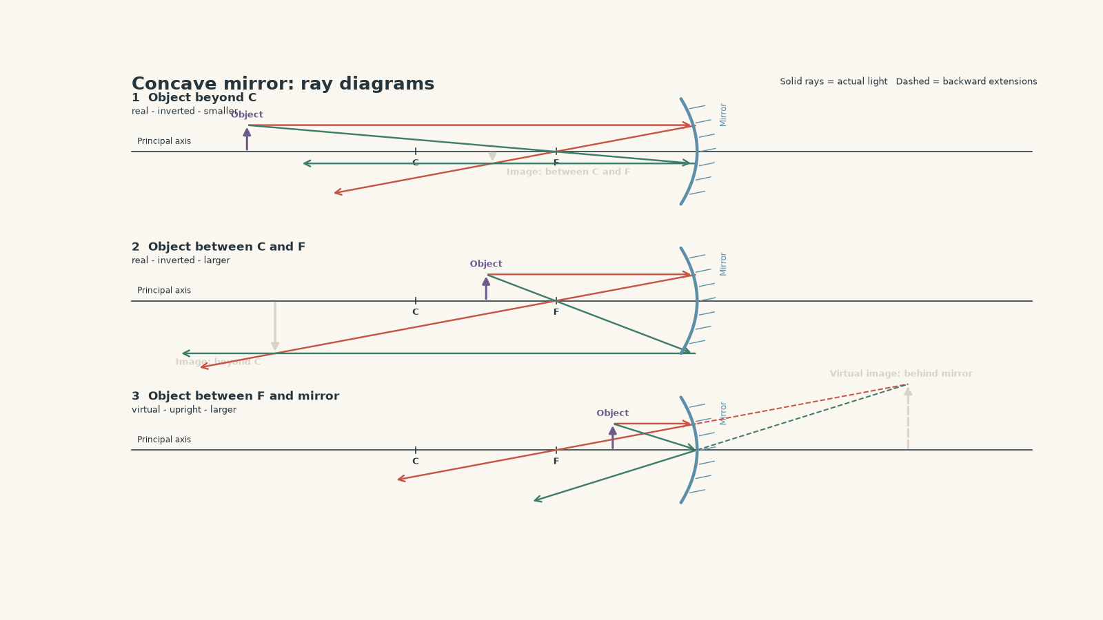
There is a pattern hiding in the table.
When the object is outside the focal point, the reflected rays can actually converge in front of the mirror. The image is real and inverted.
When the object moves inside the focal length, the reflected rays leave the mirror diverging. Their backward extensions meet behind the mirror. The image becomes virtual and upright.
That is why a concave makeup or shaving mirror can magnify your face when you move close enough to it.
Worked example: object beyond the centre of curvature
A concave mirror has a focal length of \(12\ \text{cm}\). An object is \(36\ \text{cm}\) in front of the mirror. Locate and describe the image.
Step 1
The focal point is \(12\ \text{cm}\) from the mirror.
For the spherical-mirror model,
\[ R = 2f = 2(12\ \text{cm}) = 24\ \text{cm} \]
so \(C\) is \(24\ \text{cm}\) in front of the mirror.
The object is at \(36\ \text{cm}\), so it is beyond \(C\).
Step 2
A ray parallel to the axis reflects through \(F\).
A second ray through \(C\) reflects back along itself.
Those reflected rays meet between \(F\) and \(C\), so the image should be real, inverted, and smaller than the object.
Step 3
For a spherical mirror,
\[ \frac{1}{f}=\frac{1}{d_o}+\frac{1}{d_i} \]
where \(f\) is focal length, \(d_o\) is object distance, and \(d_i\) is image distance.
Using \(f=12\ \text{cm}\) and \(d_o=36\ \text{cm}\),
\[ \frac{1}{12}=\frac{1}{36}+\frac{1}{d_i} \]
\[ \frac{1}{d_i} =\frac{1}{12}-\frac{1}{36} =\frac{3-1}{36} =\frac{1}{18} \]
so
\[ d_i=18\ \text{cm} \]
The image is \(18\ \text{cm}\) in front of the mirror, which is indeed between \(F\) at \(12\ \text{cm}\) and \(C\) at \(24\ \text{cm}\).
Step 4
Mirror magnification is
\[ m=\frac{h_i}{h_o}=-\frac{d_i}{d_o} \]
where \(h_i\) and \(h_o\) are image and object heights.
\[ m=-\frac{18}{36}=-0.50 \]
The negative sign means the image is inverted. Its magnitude, \(0.50\), means it is half the object’s height.
So the image is real, inverted, half the object’s height, and \(18\ \text{cm}\) in front of the mirror.
08The focal point is a boundary, not a magic wall
Now predict what happens as an object approaches \(F\) from outside the focal length.
You might expect the image to approach the mirror too. In fact, the opposite happens.
The reflected rays become less strongly convergent, so they meet farther and farther away. At exactly \(F\), rays from an on-axis point emerge parallel in the idealised model. Parallel rays do not meet at any finite distance.
We describe the image as being at infinity.
Then move the object just inside \(F\). The reflected rays now diverge. Their backward extensions meet behind the mirror, producing an upright virtual image.
This change is why the focal point is such an important boundary in ray diagrams.
Worked example: object inside the focal length
A concave mirror has a focal length of \(10\ \text{cm}\). An object is placed \(6.0\ \text{cm}\) in front of it. Locate and describe the image.
Step 1
The object lies between \(F\) and the mirror.
A ray parallel to the axis reflects through \(F\). Another ray aimed towards \(F\) reflects parallel to the axis.
After reflection, these rays spread apart. Extend them backwards behind the mirror, and their extensions meet.
So the image must be virtual and upright.
Step 2
With the sign convention used here, a concave mirror has positive \(f\), a normal object in front of the mirror has positive \(d_o\), and a virtual image behind the mirror has negative \(d_i\).
\[ \frac{1}{10}=\frac{1}{6.0}+\frac{1}{d_i} \]
Therefore,
\[ \frac{1}{d_i} =\frac{1}{10}-\frac{1}{6} =\frac{3-5}{30} =-\frac{1}{15} \]
so
\[ d_i=-15\ \text{cm} \]
The negative value means the image is \(15\ \text{cm}\) behind the mirror.
Step 3
\[ m=-\frac{d_i}{d_o} =-\frac{-15}{6.0} =+2.5 \]
The positive sign means upright. The magnitude \(2.5\) means the image is \(2.5\) times the object’s height.
The image is therefore virtual, upright, enlarged by a factor of \(2.5\), and apparently \(15\ \text{cm}\) behind the mirror.
This is one of the most useful cases to understand because it defeats a common shortcut: a concave mirror does not always make a real, inverted image. Object position matters.
09Convex mirrors always make diverging reflected rays
A convex mirror behaves differently.
A ray travelling parallel to the principal axis reflects away from the axis. If you extend the reflected ray backwards, it appears to have come from the focal point behind the mirror.
For a convex mirror:
- a ray parallel to the principal axis reflects as though it came from \(F\)
- a ray aimed towards \(F\) behind the mirror reflects parallel to the axis
- a ray aimed towards \(C\) behind the mirror returns along its original path
The points \(F\) and \(C\) are both behind the mirror.
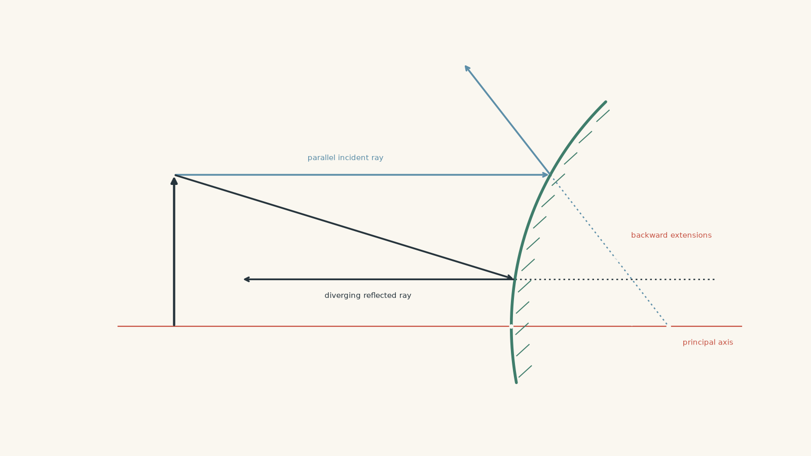
No matter where a normal real object is placed in front of a convex mirror, its image is:
- virtual
- upright
- smaller than the object
- behind the mirror
- between the mirror and \(F\)
That explains why convex mirrors are useful when a wide field of view matters. Making each image smaller allows light from a wider range of directions to fit into the mirror.
The trade-off is important: objects look smaller, so judging their distance by apparent size can be misleading.
10A reliable way to describe any mirror image
Once you have drawn the rays, describe the image using four features:
- Size: enlarged, diminished, or the same size.
- Orientation: upright or inverted.
- Location: where it forms relative to \(F\), \(C\), and the mirror.
- Type: real or virtual.
Some students remember this as SALT: size, attitude, location, type. The acronym is useful, but the ray diagram still has to justify the answer.
Do not decide that an image is real merely because you have drawn lines crossing. Ask what kind of lines are crossing.
If the solid reflected rays cross, the image is real.
If only the backward extensions cross, the image is virtual.
11The most tempting ray-diagram mistakes
Mistake 1: forcing every image to appear in front of the mirror
This often happens because students expect an image to be where light physically goes.
Virtual images break that intuition. The image position can be behind the mirror even though no reflected light travels there.
Mistake 2: extending the wrong rays
For a virtual image, extend the reflected rays backwards.
Do not simply continue the incident rays straight through the mirror. The apparent image must correspond to the direction from which the reflected light seems to arrive.
Mistake 3: drawing one ray and guessing the rest
One ray gives a direction, not a unique image point.
Two correctly drawn rays from the same object point are enough to locate their intersection.
Mistake 4: treating the focal point as a place every ray must pass through
Only particular principal rays behave that way.
A ray parallel to the principal axis reflects through \(F\) for a concave mirror. A completely arbitrary incident ray does not automatically reflect through the focus.
Mistake 5: trusting an equation after drawing an impossible diagram
The mirror equation is useful, but the ray diagram tells you what the signs and result physically mean.
If your calculation says \(d_i<0\), but you have drawn solid reflected rays meeting in front of the mirror, something is inconsistent. Check the diagram and the sign convention.
12Questions and solutions
Question 1
A toy car is placed \(45\ \text{cm}\) in front of a plane mirror.
State the location, size, orientation, and type of its image. Also determine the distance between the car and its image.
Solution 1
The image is \(45\ \text{cm}\) behind the mirror, the same size as the car, upright, and virtual, and the car-image separation is \(90\ \text{cm}\).
A plane mirror places the image the same perpendicular distance behind the mirror as the object is in front.
Therefore,
\[ \text{separation}=45\ \text{cm}+45\ \text{cm}=90\ \text{cm} \]
The image is virtual because the reflected rays do not actually travel through the point behind the mirror. Their backward extensions meet there.
Question 2
A student draws a ray diagram for a convex mirror. The reflected rays spread apart, so the student concludes, “No image forms because the rays never meet.”
Explain the error and describe the image that does form.
Solution 2
An image does form, and it is virtual, upright, diminished, and behind the mirror between the mirror and \(F\).
The student’s mistake is assuming that rays must physically meet for any image to exist.
After reflection from a convex mirror, the rays diverge. However, an observer traces those rays backwards in straight lines. The backward extensions intersect behind the mirror, giving an apparent source of the light.
Because only extensions of the reflected rays meet there, the image is virtual rather than real.
Question 3
A concave mirror has \(f=8.0\ \text{cm}\). An object is placed \(24\ \text{cm}\) in front of the mirror.
Calculate the image position and magnification, then describe the image.
Solution 3
The image forms \(12\ \text{cm}\) in front of the mirror and is real, inverted, and half the object’s height.
Use
\[ \frac{1}{f}=\frac{1}{d_o}+\frac{1}{d_i} \]
with \(f=8.0\ \text{cm}\) and \(d_o=24\ \text{cm}\):
\[ \frac{1}{8.0}=\frac{1}{24}+\frac{1}{d_i} \]
\[ \frac{1}{d_i} =\frac{1}{8}-\frac{1}{24} =\frac{3-1}{24} =\frac{1}{12} \]
Therefore,
\[ d_i=12\ \text{cm} \]
The positive image distance means a real image forms in front of the mirror.
Now calculate magnification:
\[ m=-\frac{d_i}{d_o} =-\frac{12}{24} =-0.50 \]
The negative sign means inverted, while \(|m|=0.50\) means half-size.
There is also a useful ray-diagram check. Since \(C=2f=16\ \text{cm}\), the object at \(24\ \text{cm}\) is beyond \(C\). A concave mirror should therefore form a smaller real image between \(C\) and \(F\). The calculated position, \(12\ \text{cm}\), is exactly in that region.
Question 4
An object is moved slowly towards a concave mirror. It begins beyond \(C\), passes through \(C\), and continues towards \(F\), but does not pass inside \(F\).
A student claims that the image must move steadily towards the mirror because the object is moving towards the mirror.
Is that prediction correct? Describe how the image actually changes.
Solution 4
The prediction is incorrect. As the object moves from beyond \(C\) towards \(F\), the real image moves generally away from the mirror, while becoming larger.
When the object is beyond \(C\), the image lies between \(F\) and \(C\) and is diminished.
When the object reaches \(C\), the image is also at \(C\) and is the same size as the object.
When the object moves between \(C\) and \(F\), the image moves beyond \(C\) and becomes enlarged.
As the object approaches \(F\), the reflected rays become closer to parallel, so their intersection moves farther away. In the ideal model, the image distance approaches infinity as the object distance approaches the focal length.
The tempting mistake is to assume that object motion and image motion must have the same direction. The image position is determined by the changing directions of the reflected rays, not by mechanically copying the object’s movement.
Question 5
A small object is placed exactly at the focal point of an ideal concave mirror.
One student says a real image forms at \(F\) because “the focus is where reflected rays meet”. Another says no reflection occurs because the mirror cannot form an image.
Evaluate both claims and state what the ray model predicts.
Solution 5
Both claims are incorrect. The mirror still reflects the light, but the ideal ray model gives no image at any finite distance.
Consider rays leaving a point on the object. A principal ray that passes through \(F\) before striking the mirror reflects parallel to the principal axis. More generally, rays from an object at the focal plane are reflected so that the corresponding image is effectively at infinity in the paraxial model.
The first student’s mistake is treating \(F\) as a universal meeting point for reflected rays. The focal point has a specific meaning: rays that arrive parallel to the principal axis reflect through \(F\) for a concave mirror. It does not mean every reflected ray always goes to \(F\).
The second student’s mistake is confusing “no finite image” with “no reflection”. The law of reflection still applies normally at the mirror surface.
The mirror equation shows the limiting behaviour:
\[ \frac{1}{f}=\frac{1}{d_o}+\frac{1}{d_i} \]
With \(d_o=f\),
\[ \frac{1}{f}=\frac{1}{f}+\frac{1}{d_i} \]
so
\[ \frac{1}{d_i}=0 \]
which corresponds to \(d_i\) tending towards infinity.
The interesting physics is therefore not that the light disappears, but that the reflected rays fail to converge at any finite position.
13Where this idea leads next
Ray diagrams turn the law of reflection into a prediction about what an observer actually sees. Once you can decide where reflected rays meet, or where they only appear to meet, the same reasoning transfers naturally to refraction and lenses.
The geometry changes when light crosses between materials because the ray can bend rather than reflect, but the central question stays the same: after the light has changed direction, where do the rays actually go, and where would an observer trace them back to?