
Parallel Circuits: Voltage, Current, Resistance and Power
Learn how voltage, branch current, equivalent resistance, and power behave in parallel circuits, with worked HSC Physics examples and challenging practice.
Imagine two identical lamps connected to the same battery. You add a third lamp on its own parallel branch. What should happen to the first two lamps? A common prediction is that they become dimmer because the battery’s current now has to be “shared” three ways. For an ideal constant-voltage supply, that prediction is wrong. The first two lamps keep the same voltage, so their currents stay the same. The new branch simply makes the source provide more total current.
That one idea sits underneath almost every parallel-circuit calculation: branches share voltage, not necessarily current.
01What makes a circuit parallel?
Picture a charge moving through a circuit until it reaches a junction. There are now several paths it could follow. Farther along, those paths join again.
That is a parallel section.
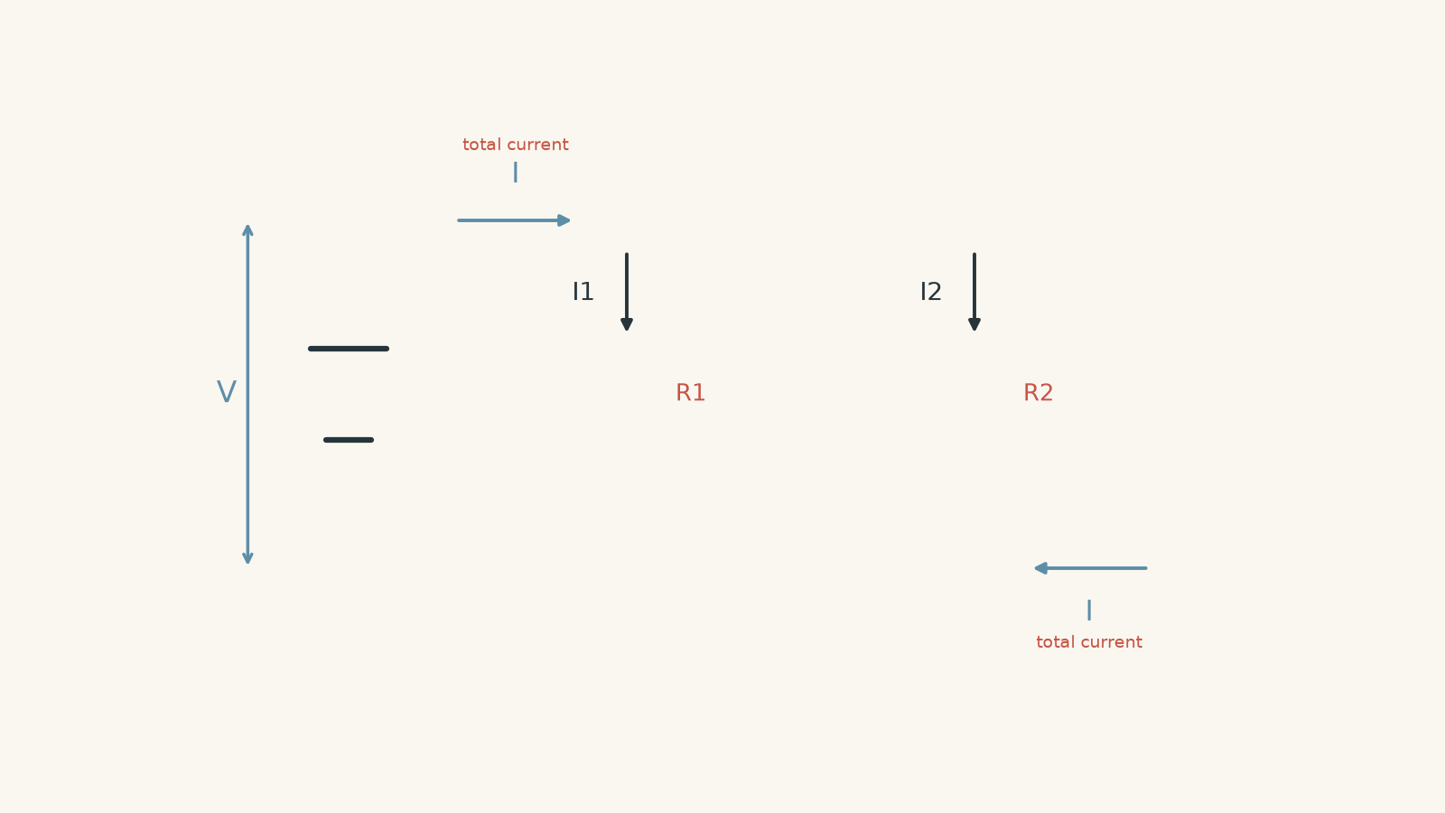
The two ends of every branch are connected to the same two circuit points. That matters because voltage is a difference in electric potential between two points.
If each branch starts at point A and finishes at point B, every branch has the same potential difference:
\[
V_{\text{supply}} = V_1 = V_2 = V_3 = \cdots
\]
This is the first rule to lock in:
The voltage across parallel branches is the same.
That does not mean the current in each branch is the same.
Before going further, predict this: two resistors, \(4\ \Omega\) and \(12\ \Omega\), are connected in parallel across the same battery. Which branch carries more current?
The \(4\ \Omega\) branch does. Both branches experience the same voltage, but the smaller resistance allows a larger current.
Using Ohm’s law,
\[
I = \frac{V}{R}
\]
so, for the same \(V\), a larger \(R\) gives a smaller \(I\).
If you need a refresher on when \(V = IR\) can be used directly, see Ohm’s Law in HSC Physics: When Resistance Is Constant.
02Branch current: where does the total current go?
Current is the rate at which charge passes a point. At a junction, charge does not disappear, pile up indefinitely, or get “used up”.
So the total current entering a junction must equal the total current leaving it.
For three parallel branches,
\[
I_{\text{total}} = I_1 + I_2 + I_3
\]
This is conservation of charge.
A useful mental model is people arriving at a train station with several exit gates. If 200 people per minute enter the gate area, then, once things are running steadily, the exit gates together must pass 200 people per minute. One gate might handle 120 people per minute and another 80 people per minute, but the totals have to match.
The analogy has limits. Electric current is not a stream of individual charges choosing a route after thinking about which resistor looks nicer. The current distribution is established by the electric field throughout the circuit. The analogy is only meant to help with conservation.
For ordinary resistor branches, we can calculate each current separately:
\[
I_1 = \frac{V}{R_1}, \qquad
I_2 = \frac{V}{R_2}, \qquad
I_3 = \frac{V}{R_3}
\]
because the same voltage \(V\) is across every branch.
Worked example: Find the currents in two parallel branches
A \(12\ \text{V}\) ideal supply is connected across a \(6.0\ \Omega\) resistor and a \(3.0\ \Omega\) resistor in parallel. Find the current in each branch and the total current supplied.
Step 1
Both resistors are connected directly across the \(12\ \text{V}\) supply, so
\[
V_1 = V_2 = 12\ \text{V}
\]
Step 2
\[
I_1 = \frac{V}{R_1}
= \frac{12}{6.0}
= 2.0\ \text{A}
\]
Step 3
\[
I_2 = \frac{V}{R_2}
= \frac{12}{3.0}
= 4.0\ \text{A}
\]
Step 4
\[
I_{\text{total}} = I_1 + I_2
= 2.0 + 4.0
= 6.0\ \text{A}
\]
The \(3.0\ \Omega\) branch carries twice the current of the \(6.0\ \Omega\) branch because it has half the resistance, while both have the same voltage.
03Why the current does not “split equally”
Students often remember the phrase “current splits at a junction” and accidentally turn that into “current splits equally”.
It only splits equally when the branches have equal electrical behaviour.
For two ideal resistors,
\[
I_1 = \frac{V}{R_1}
\]
and
\[
I_2 = \frac{V}{R_2}
\]
so
\[
\frac{I_1}{I_2} = \frac{R_2}{R_1}
\]
The currents are inversely related to the resistances.
For example, if one branch has three times the resistance of another, it carries one-third of the current, provided both branches have the same voltage and behave ohmically.
This gives a useful decision rule:
| If two parallel branches have… | Then… |
|---|---|
| equal resistance | equal current |
| different resistance | different current |
| smaller resistance | larger current |
| larger resistance | smaller current |
| the same two connection points | the same voltage |
04Equivalent resistance: replacing the whole parallel network
Suppose a battery sees several parallel resistors. From the battery’s point of view, we can replace the entire group with one equivalent resistance, \(R_{\text{eq}}\), that would draw the same total current at the same voltage.
For the whole network,
\[
I_{\text{total}} = \frac{V}{R_{\text{eq}}}
\]
But the total current is also the sum of the branch currents:
\[
I_{\text{total}}
=
\frac{V}{R_1}
+
\frac{V}{R_2}
+
\frac{V}{R_3}
+\cdots
\]
Therefore,
\[
\frac{V}{R_{\text{eq}}}
=
\frac{V}{R_1}
+
\frac{V}{R_2}
+
\frac{V}{R_3}
+\cdots
\]
For a non-zero voltage, divide every term by \(V\):
\[
\frac{1}{R_{\text{eq}}}
=
\frac{1}{R_1}
+
\frac{1}{R_2}
+
\frac{1}{R_3}
+\cdots
\]
That is the parallel-resistance equation.
For two resistors only, it can also be rearranged to
\[
R_{\text{eq}} = \frac{R_1R_2}{R_1+R_2}
\]
The reciprocal form is more general, so it is usually the safer one to remember.
05Why parallel resistance gets smaller
Here is the result that often feels wrong at first:
The equivalent resistance of resistors in parallel is smaller than the smallest individual resistance.
Suppose you already have one path for charge. Adding another parallel path does not make it harder for the source to drive current. It gives the circuit an additional route.
Think of a crowded school leaving through one doorway. Opening a second doorway makes it easier for more people to leave each second. The doors are not literally resistors, but the analogy captures why providing another path increases the total flow for a given driving difference.
That means the circuit draws more current at the same voltage.
Since
\[
R_{\text{eq}} = \frac{V}{I_{\text{total}}},
\]
a larger total current at the same voltage means a smaller equivalent resistance.
There is also a quick mathematical check. Because
\[
\frac{1}{R_{\text{eq}}}
=
\frac{1}{R_1}
+
\frac{1}{R_2},
\]
the reciprocal of \(R_{\text{eq}}\) is larger than either reciprocal on its own. Therefore \(R_{\text{eq}}\) must be smaller than either individual resistance.
If your calculation gives an equivalent resistance larger than the smallest parallel resistor, something has gone wrong.
06A special case worth knowing
For \(n\) identical resistors, each of resistance \(R\), connected in parallel,
\[
\frac{1}{R_{\text{eq}}}
=
\frac{n}{R}
\]
so
\[
R_{\text{eq}} = \frac{R}{n}
\]
For example, three \(12\ \Omega\) resistors in parallel have
\[
R_{\text{eq}} = \frac{12}{3} = 4.0\ \Omega
\]
This shortcut works only when all the parallel resistances are equal.
07Power in parallel branches
Electrical power tells us the rate at which electrical energy is transferred.
For any circuit element,
\[
P = VI
\]
where:
- \(P\) is power in watts, \(\text{W}\)
- \(V\) is potential difference in volts, \(\text{V}\)
- \(I\) is current in amperes, \(\text{A}\)
For an ohmic resistor, combining \(P = VI\) with \(V = IR\) gives
\[
P = \frac{V^2}{R}
\]
and
\[
P = I^2R
\]
In a parallel circuit, \(P = V^2/R\) is particularly useful because the voltage across each branch is known to be the same.
For two resistor branches,
\[
P_1 = \frac{V^2}{R_1}
\]
and
\[
P_2 = \frac{V^2}{R_2}
\]
At a fixed voltage, the lower-resistance branch has the greater power.
That might initially seem strange if you remember \(P = I^2R\) and think “larger resistance means more power”. The missing piece is that the current is not the same in parallel branches. \(P = I^2R\) only supports that comparison when \(I\) is fixed.
In parallel, voltage is fixed across the branches. So \(P = V^2/R\) is the clearer comparison.
The total power supplied is
\[
P_{\text{total}} = P_1 + P_2 + P_3 + \cdots
\]
It can also be calculated using the equivalent resistance:
\[
P_{\text{total}}
=
VI_{\text{total}}
=
\frac{V^2}{R_{\text{eq}}}
\]
For more detail on choosing between the power equations, see Electrical Power in HSC Physics: Using P = VI and Equivalent Forms.
Worked example: Find an unknown branch resistance and the total power
An ideal \(18\ \text{V}\) supply is connected to two parallel resistors. One resistor has resistance \(9.0\ \Omega\). The total current from the supply is \(5.0\ \text{A}\). Find the second resistance, the equivalent resistance, and the total power supplied.
Step 1
Each branch has the full \(18\ \text{V}\) across it.
\[
I_1 = \frac{V}{R_1}
= \frac{18}{9.0}
= 2.0\ \text{A}
\]
Step 2
The total current is \(5.0\ \text{A}\), so
\[
I_{\text{total}} = I_1 + I_2
\]
\[
5.0 = 2.0 + I_2
\]
\[
I_2 = 3.0\ \text{A}
\]
Step 3
The second branch also has \(18\ \text{V}\) across it.
\[
R_2 = \frac{V}{I_2}
= \frac{18}{3.0}
= 6.0\ \Omega
\]
Step 4
Using the supply voltage and total current,
\[
R_{\text{eq}}
=
\frac{V}{I_{\text{total}}}
=
\frac{18}{5.0}
=
3.6\ \Omega
\]
This passes the quick check: \(3.6\ \Omega\) is smaller than both \(6.0\ \Omega\) and \(9.0\ \Omega\).
Step 5
\[
P_{\text{total}}
=
VI_{\text{total}}
=
18 \times 5.0
=
90\ \text{W}
\]
So the network draws \(5.0\ \text{A}\), behaves like a single \(3.6\ \Omega\) resistor from the supply’s point of view, and transfers electrical energy at \(90\ \text{J s}^{-1}\).
As a check, the branch powers are
\[
P_1 = VI_1 = 18 \times 2.0 = 36\ \text{W}
\]
and
\[
P_2 = VI_2 = 18 \times 3.0 = 54\ \text{W}
\]
giving
\[
P_{\text{total}} = 36 + 54 = 90\ \text{W}
\]
as required.
08What happens when another branch is added?
Suppose a \(12\ \Omega\) resistor is connected across an ideal \(24\ \text{V}\) source.
Its current is
\[
I = \frac{24}{12} = 2.0\ \text{A}
\]
Now connect another \(12\ \Omega\) resistor in parallel.
Predict what happens to the current through the original resistor.
It remains \(2.0\ \text{A}\).
The original branch still has \(24\ \text{V}\) across \(12\ \Omega\), so nothing in \(I = V/R\) has changed for that branch.
The new resistor also draws \(2.0\ \text{A}\), so the source current becomes
\[
I_{\text{total}} = 2.0 + 2.0 = 4.0\ \text{A}
\]
The equivalent resistance has fallen from \(12\ \Omega\) to
\[
R_{\text{eq}} = \frac{12}{2} = 6.0\ \Omega
\]
and the total power has increased from
\[
P_{\text{old}} = VI = 24 \times 2.0 = 48\ \text{W}
\]
to
\[
P_{\text{new}} = 24 \times 4.0 = 96\ \text{W}
\]
So adding a parallel branch to an ideal fixed-voltage source causes:
- the branch voltage to stay the same
- existing resistor branch currents to stay the same
- total current to increase
- equivalent resistance to decrease
- total power supplied to increase
This is almost the opposite of what happens when another resistor is added in series.
09The important hidden assumption: an ideal voltage source
The statement “adding a parallel branch does not affect the other branch currents” assumes the source maintains the same terminal voltage.
That is the standard model for many HSC circuit questions unless the problem tells you otherwise.
A real battery has internal resistance and other limitations. If a large extra current is drawn, its terminal voltage can fall. In that situation, the voltage across every branch may decrease slightly, so the existing branch currents can also decrease.
The simplified model is still useful. The key is knowing what it assumes.
When a question gives a fixed supply voltage and does not introduce internal resistance, treat the branch voltage as fixed.
10Four relationships to keep separate
Parallel-circuit mistakes often come from mixing up relationships that belong to different quantities.
| Quantity | Parallel-circuit relationship |
|---|---|
| Voltage | \(V_{\text{supply}} = V_1 = V_2 = \cdots\) |
| Current | \(I_{\text{total}} = I_1 + I_2 + \cdots\) |
| Resistance | \(\frac{1}{R_{\text{eq}}} = \frac{1}{R_1} + \frac{1}{R_2} + \cdots\) |
| Power | \(P_{\text{total}} = P_1 + P_2 + \cdots\) |
A useful way to decide what to do is:
- Identify which components are genuinely in parallel by checking whether they share the same two endpoints.
- Mark the common voltage across those branches.
- Use \(I = V/R\) for each resistor branch.
- Add branch currents to find total current.
- Use the reciprocal equation if you need equivalent resistance.
- Calculate power using whichever form matches the quantities you actually know.
Do not start by blindly hunting for an equation. First ask what the circuit structure tells you.
11Questions and solutions
Question 1
A \(15\ \text{V}\) ideal supply is connected to a \(10\ \Omega\) resistor and a \(30\ \Omega\) resistor in parallel.
Find:
- the current through each resistor
- the total current supplied
- the equivalent resistance
Solution 1
The branch currents are \(1.5\ \text{A}\) and \(0.50\ \text{A}\), the total current is \(2.0\ \text{A}\), and the equivalent resistance is \(7.5\ \Omega\).
Both branches have the full \(15\ \text{V}\) across them.
For the \(10\ \Omega\) resistor,
\[
I_1 = \frac{V}{R_1}
= \frac{15}{10}
= 1.5\ \text{A}
\]
For the \(30\ \Omega\) resistor,
\[
I_2 = \frac{V}{R_2}
= \frac{15}{30}
= 0.50\ \text{A}
\]
The total current is the sum of the branch currents:
\[
I_{\text{total}}
=
1.5 + 0.50
=
2.0\ \text{A}
\]
Then
\[
R_{\text{eq}}
=
\frac{V}{I_{\text{total}}}
=
\frac{15}{2.0}
=
7.5\ \Omega
\]
The equivalent resistance is correctly smaller than the smallest branch resistance, \(10\ \Omega\).
Question 2
Three resistors of \(4.0\ \Omega\), \(6.0\ \Omega\), and \(12\ \Omega\) are connected in parallel across an ideal \(12\ \text{V}\) supply.
Find the total current, equivalent resistance, and total power.
Solution 2
The total current is \(6.0\ \text{A}\), the equivalent resistance is \(2.0\ \Omega\), and the total power is \(72\ \text{W}\).
Each resistor has \(12\ \text{V}\) across it.
The branch currents are
\[
I_1 = \frac{12}{4.0} = 3.0\ \text{A}
\]
\[
I_2 = \frac{12}{6.0} = 2.0\ \text{A}
\]
and
\[
I_3 = \frac{12}{12} = 1.0\ \text{A}
\]
Therefore,
\[
I_{\text{total}}
=
3.0 + 2.0 + 1.0
=
6.0\ \text{A}
\]
The equivalent resistance is
\[
R_{\text{eq}}
=
\frac{V}{I_{\text{total}}}
=
\frac{12}{6.0}
=
2.0\ \Omega
\]
The total power is
\[
P_{\text{total}}
=
VI_{\text{total}}
=
12 \times 6.0
=
72\ \text{W}
\]
The current pattern also makes physical sense. The \(4.0\ \Omega\) branch has the smallest resistance and carries the greatest current.
Question 3
A \(24\ \text{V}\) ideal supply is connected to an \(8.0\ \Omega\) resistor and a \(12\ \Omega\) resistor in parallel. A switch then disconnects the \(8.0\ \Omega\) branch.
Determine the current through the \(12\ \Omega\) resistor before and after the switch is opened. Also determine the total current before and after.
Solution 3
The \(12\ \Omega\) branch current stays at \(2.0\ \text{A}\). The total current falls from \(5.0\ \text{A}\) to \(2.0\ \text{A}\).
Before the switch opens, both resistors have \(24\ \text{V}\) across them.
For the \(8.0\ \Omega\) branch,
\[
I_1
=
\frac{24}{8.0}
=
3.0\ \text{A}
\]
For the \(12\ \Omega\) branch,
\[
I_2
=
\frac{24}{12}
=
2.0\ \text{A}
\]
So initially,
\[
I_{\text{total}}
=
3.0 + 2.0
=
5.0\ \text{A}
\]
After the \(8.0\ \Omega\) branch is disconnected, the \(12\ \Omega\) resistor is still connected directly across the same ideal \(24\ \text{V}\) supply.
Therefore,
\[
I_2
=
\frac{24}{12}
=
2.0\ \text{A}
\]
and it is now the only branch, so
\[
I_{\text{total}} = 2.0\ \text{A}
\]
The tempting mistake is to think that the original \(5.0\ \text{A}\) must now flow through the remaining branch. It does not. The source current is determined by the resistance connected to the source and its voltage. Removing a branch changes the total current drawn.
Question 4
A \(20\ \text{V}\) ideal supply is connected to \(10\ \Omega\) and \(40\ \Omega\) resistors in parallel. A \(200\ \Omega\) resistor is then added as a third parallel branch.
A student argues that the new resistor has such a large resistance that it should make the equivalent resistance slightly larger.
Calculate the equivalent resistance before and after the \(200\ \Omega\) branch is added, and explain whether the student’s reasoning is correct.
Solution 4
The equivalent resistance decreases from \(8.0\ \Omega\) to approximately \(7.69\ \Omega\). The student’s reasoning is incorrect because adding any finite-resistance parallel path increases total conductance.
Before the new branch is added,
\[
\frac{1}{R_{\text{eq,1}}}
=
\frac{1}{10}
+
\frac{1}{40}
=
0.100 + 0.025
=
0.125\ \Omega^{-1}
\]
so
\[
R_{\text{eq,1}}
=
\frac{1}{0.125}
=
8.0\ \Omega
\]
After the \(200\ \Omega\) branch is added,
\[
\frac{1}{R_{\text{eq,2}}}
=
\frac{1}{10}
+
\frac{1}{40}
+
\frac{1}{200}
\]
\[
\frac{1}{R_{\text{eq,2}}}
=
0.100 + 0.025 + 0.005
=
0.130\ \Omega^{-1}
\]
Therefore,
\[
R_{\text{eq,2}}
=
\frac{1}{0.130}
\approx
7.69\ \Omega
\]
The \(200\ \Omega\) branch carries only a small current,
\[
I
=
\frac{20}{200}
=
0.10\ \text{A}
\]
but that current is still additional current. At the same supply voltage, increasing the total current means decreasing the equivalent resistance.
A very large branch resistance can have a tiny effect, but it cannot increase the equivalent resistance.
In the limiting case \(R \to \infty\), the new branch current approaches zero and the branch has essentially no effect.
Question 5
Two identical \(12\ \Omega\) lamps are connected in parallel across an ideal \(24\ \text{V}\) supply. Treat each lamp as having constant resistance for this question.
One lamp fails by becoming an open circuit.
A student says, “The other lamp should become brighter because the source now has only one lamp to power.”
Determine the current through each lamp before the failure, the source current before and after the failure, and the power of the surviving lamp before and after. Explain the student’s error.
Solution 5
The surviving lamp remains at \(48\ \text{W}\), so under the stated ideal-circuit model its brightness does not increase. The source current falls from \(4.0\ \text{A}\) to \(2.0\ \text{A}\).
Before the failure, each lamp has \(24\ \text{V}\) across \(12\ \Omega\).
The current through each lamp is
\[
I
=
\frac{V}{R}
=
\frac{24}{12}
=
2.0\ \text{A}
\]
Therefore the initial source current is
\[
I_{\text{total}}
=
2.0 + 2.0
=
4.0\ \text{A}
\]
The power of each lamp is
\[
P
=
VI
=
24 \times 2.0
=
48\ \text{W}
\]
When one lamp becomes an open circuit, no current flows through that failed branch.
The surviving lamp is still connected across the ideal \(24\ \text{V}\) supply, so
\[
I_{\text{surviving}}
=
\frac{24}{12}
=
2.0\ \text{A}
\]
The source current is therefore now
\[
I_{\text{total}} = 2.0\ \text{A}
\]
and the surviving lamp’s power remains
\[
P
=
24 \times 2.0
=
48\ \text{W}
\]
The student’s mistake is treating the supply as if it delivers a fixed amount of current or power that must be divided among whatever components are connected. An ideal voltage source instead maintains a fixed voltage. Each branch then draws the current determined by that voltage and its own resistance.
With a real source that has internal resistance, removing a branch could cause a small change in terminal voltage. That possibility is outside the ideal model used here.
Question 6
Two resistors, \(R_1 = 6.0\ \Omega\) and \(R_2 = 12\ \Omega\), are connected in parallel. A power supply is adjusted so that the total current remains fixed at \(6.0\ \text{A}\).
A third \(12\ \Omega\) resistor is then added in parallel, and the supply voltage is readjusted so the total current is still \(6.0\ \text{A}\).
Determine the voltage and current through the \(6.0\ \Omega\) resistor before and after the third branch is added. Explain why this result differs from the usual statement that adding a parallel branch leaves existing branch currents unchanged.
Solution 6
The voltage falls from \(24\ \text{V}\) to \(18\ \text{V}\), and the current through the \(6.0\ \Omega\) resistor falls from \(4.0\ \text{A}\) to \(3.0\ \text{A}\). The usual unchanged-current result only applies when the supply voltage is held constant.
Initially,
\[
\frac{1}{R_{\text{eq,1}}}
=
\frac{1}{6.0}
+
\frac{1}{12}
=
\frac{2}{12}+\frac{1}{12}
=
\frac{3}{12}
\]
so
\[
R_{\text{eq,1}} = 4.0\ \Omega
\]
The total current is fixed at \(6.0\ \text{A}\), so the initial supply voltage is
\[
V_1
=
I_{\text{total}}R_{\text{eq,1}}
=
6.0 \times 4.0
=
24\ \text{V}
\]
The current through the \(6.0\ \Omega\) branch is
\[
I_{6,1}
=
\frac{24}{6.0}
=
4.0\ \text{A}
\]
After a second \(12\ \Omega\) branch is added,
\[
\frac{1}{R_{\text{eq,2}}}
=
\frac{1}{6.0}
+
\frac{1}{12}
+
\frac{1}{12}
\]
\[
\frac{1}{R_{\text{eq,2}}}
=
\frac{2}{12}
+
\frac{1}{12}
+
\frac{1}{12}
=
\frac{4}{12}
=
\frac{1}{3}
\]
so
\[
R_{\text{eq,2}} = 3.0\ \Omega
\]
To keep the total current at \(6.0\ \text{A}\), the supply must now be set to
\[
V_2
=
I_{\text{total}}R_{\text{eq,2}}
=
6.0 \times 3.0
=
18\ \text{V}
\]
The current through the \(6.0\ \Omega\) branch becomes
\[
I_{6,2}
=
\frac{18}{6.0}
=
3.0\ \text{A}
\]
The important hidden assumption has changed. In the usual parallel-circuit problem, voltage is held constant, so adding another branch leaves the voltage and current of existing branches unchanged. Here, total current is deliberately held constant instead. Because the equivalent resistance falls, the supply voltage must also fall, which changes every branch current.
That distinction is useful whenever a circuit question changes what is being held constant. Parallel-circuit rules do not replace \(V = IR\). They tell you which voltages and currents are linked by the circuit’s structure.
Once that is secure, the next useful step is comparing parallel behaviour with series circuits, where current is common to every component and voltage is divided instead.