
Motor-Effect Direction Rules for HSC Physics Explained
Learn how to relate conventional current, magnetic field, and force directions in motor-effect problems, with worked examples and challenging practice.
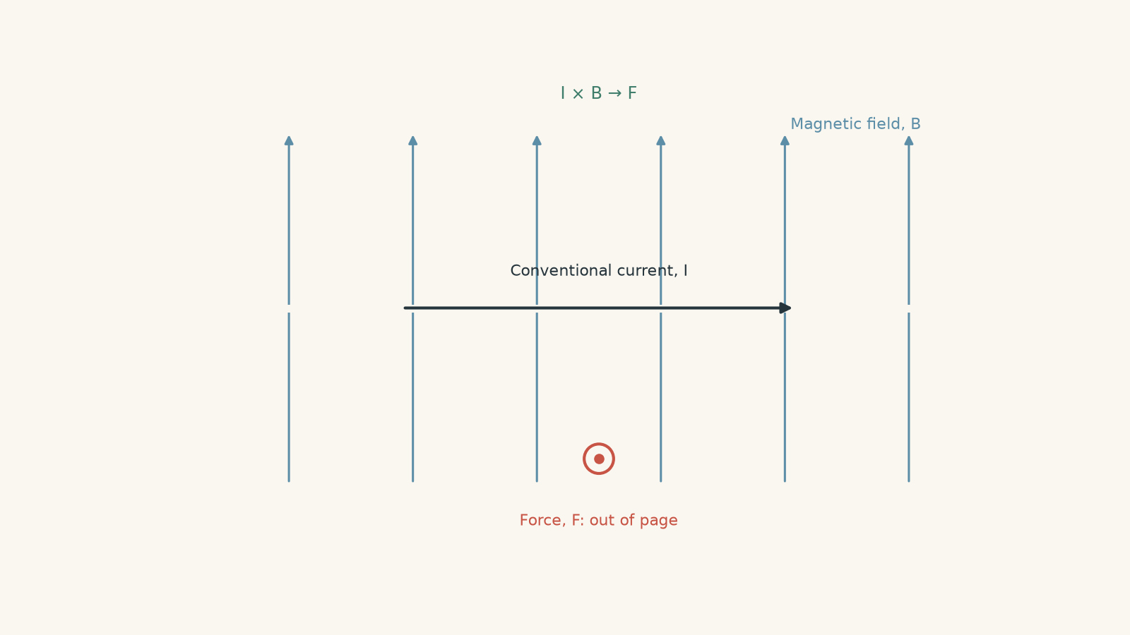
A straight wire sits between two magnet poles. The current runs to the right, and the magnetic field points upwards. The wire suddenly jumps either towards you or away from you.
Before reading on, make a prediction: which way does it move?
If you tried to combine “right” and “up” and got a diagonal direction, that is the first trap. The motor effect does something less intuitive. The force is perpendicular to both the current and the magnetic field. In this case, the force is out of the page, towards you.
That sideways relationship is what makes electric motors possible. Once you can reliably connect current, magnetic field, and force directions, motor-effect questions stop being a memory test and start becoming geometry.
01The three directions you need to track
For a straight current-carrying conductor in a magnetic field, there are three directions:
| Quantity | What direction means |
|---|---|
| Current, \(I\) | The direction of conventional current |
| Magnetic field, \(\vec B\) | The direction a north magnetic pole would be pushed |
| Force, \(\vec F\) | The direction the conductor is pushed |
The important relationship is:
\[ \vec F = I\vec L \times \vec B \]
Here, \(\vec L\) is a vector pointing along the conventional current, with magnitude equal to the length of conductor inside the magnetic field.
The \(\times\) symbol is a vector cross product. You do not need advanced vector algebra to use it in HSC Physics. Its main message is:
- the force is perpendicular to the current,
- the force is perpendicular to the magnetic field, and
- reversing either the current or the magnetic field reverses the force.
Picture the three directions before using a rule
Imagine the page as the floor.
Current runs east. The magnetic field runs north. The force cannot run north-east because it has to be perpendicular to both directions already on the floor. That leaves only two possibilities: straight up from the floor or straight down through it.
The direction rule tells you which one.
This mental picture matters. A hand rule should choose between the two possible perpendicular directions, not magically produce an answer you cannot visualise.
02Reading into and out of the page
A lot of motor-effect questions use a direction that cannot be drawn as an ordinary arrow on the page.
Two symbols solve that problem:
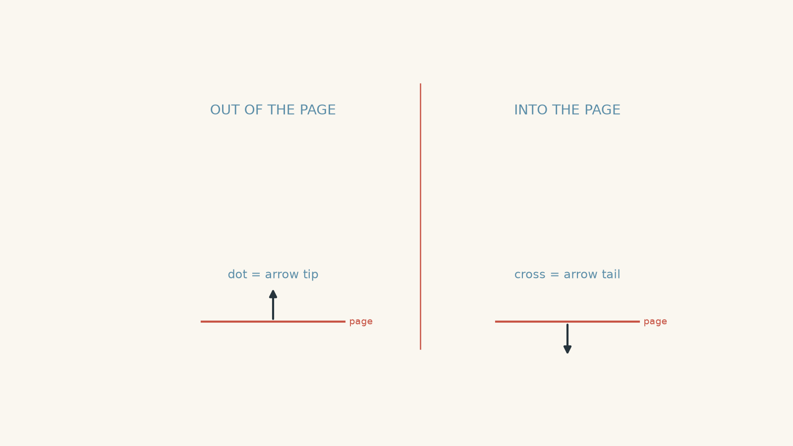
- \(\odot\) means out of the page, towards you.
- \(\otimes\) means into the page, away from you.
Think of an actual arrow flying through the page.
If the arrow is coming towards you, you see its pointed tip: a dot.
If the arrow is flying away from you, you see the crossed feathers at its tail: a cross.
That analogy is only for remembering the symbols. There is no literal arrow travelling through the wire.
03A reliable direction method
You may have been taught Fleming’s left-hand rule. It works. A right-hand cross-product rule also works. The important thing is to use one system consistently.
For the cross-product version:
- Point your right index finger along the conventional current.
- Point your middle finger along the magnetic field.
- Your thumb gives the force direction.
The order matters. It is current crossed with field:
\[ \vec F \propto \vec I \times \vec B \]
Swapping them gives the opposite direction.
For Fleming’s left-hand rule, the usual mapping is:
| Finger | Quantity |
|---|---|
| First finger | magnetic Field |
| seCond finger | Current |
| thuMb | Motion or force |
You only need one of these rules in a calculation. Using half of one rule and half of another is a surprisingly efficient way to get every direction backwards.
A useful reversal test
Suppose you already know the original force direction.
Then you often do not need to use the hand rule again.
| Change | What happens to force? |
|---|---|
| Reverse current only | Force reverses |
| Reverse magnetic field only | Force reverses |
| Reverse both | Force stays the same |
| Make current parallel to field | Force becomes zero |
The third row is especially useful. Reversing twice cancels out.
04Why does the wire feel a force at all?
A current means electric charge is moving through the conductor.
A moving charge in a magnetic field experiences a magnetic force:
\[ \vec F = q\vec v \times \vec B \]
where \(q\) is the charge, \(\vec v\) is its velocity, and \(\vec B\) is the magnetic field.
In a current-carrying wire, this microscopic magnetic interaction produces a force on the conductor as a whole. When we scale from individual moving charges to a straight section of wire, the magnitude becomes
\[ F = BIL\sin\theta \]
where:
- \(F\) is the magnetic force in newtons, N,
- \(B\) is magnetic field strength in tesla, T,
- \(I\) is conventional current in amperes, A,
- \(L\) is the length of conductor inside the field in metres, m, and
- \(\theta\) is the angle between the current direction and the magnetic field.
Notice what is missing from this equation: it does not directly tell you whether the force is left, right, into the page, or out of the page. The equation gives the magnitude. The direction rule gives the direction.
You usually need both.
05The angle tells you how much of the current direction matters
Suppose a wire is carrying current directly along the magnetic field.
Predict the force before using the equation.
There is no magnetic force on the wire.
That can feel strange at first because both \(B\) and \(I\) may be large. But
\[ F = BIL\sin 0^\circ = 0 \]
The magnetic field only produces this motor-effect force from the component of the conductor that is perpendicular to the field.
At \(90^\circ\),
\[ \sin 90^\circ = 1 \]
so the force is maximum:
\[ F_{\text{max}} = BIL \]
At an intermediate angle, only part of the geometry contributes.
This gives you a useful check before calculating. If your wire is almost parallel to the field, the force should be small. If it is perpendicular, the force should be as large as possible for those values of \(B\), \(I\), and \(L\).
Worked example: A perpendicular wire
A \(0.40\text{ m}\) section of wire carries a conventional current of \(3.0\text{ A}\) to the right through a uniform magnetic field of \(0.25\text{ T}\) directed upwards. Find the magnitude and direction of the magnetic force.
Step 1
The current points right and the magnetic field points up, so
\[ \theta = 90^\circ \]
Step 2
\[ \begin{aligned} F &= BIL\sin\theta\\ &=(0.25)(3.0)(0.40)\sin 90^\circ\\ &=0.30\text{ N} \end{aligned} \]
Step 3
Current is to the right. Field is upwards.
Using \(\vec I\times\vec B\), the force is out of the page.
So the conductor experiences a force of \(0.30\text{ N}\) out of the page.
The number tells us how strongly the wire is pushed. The direction rule tells us where it goes.
06The most tempting mistake: using electron flow as current direction
In a metal wire, electrons drift opposite to conventional current.
So suppose conventional current points right. Electrons drift left.
A student may reason:
“The charges actually move left, so I should put left into the hand rule.”
That gives the wrong answer if the rule is defined using conventional current.
There is a neat reason the conventional-current method still works.
For an individual charge,
\[ \vec F=q\vec v\times\vec B \]
An electron has two differences from a positive conventional charge:
- its velocity is opposite to the conventional current, and
- its charge \(q\) is negative.
Those are two reversals. They cancel.
For example, suppose conventional current is right and magnetic field is up. The current rule predicts force out of the page.
An electron moves left instead. The vector \(\vec v\times\vec B\) therefore points into the page. But \(q\) is negative, so the force reverses again and points out of the page.
Same physical answer.
So for motor-effect questions involving a wire, use conventional current unless the question explicitly asks you to analyse individual charge carriers.
07Magnetic-field direction is another common source of errors
Between the poles of a magnet, the external magnetic field points from north to south.
So if a north pole is drawn above a south pole, the field points downwards between them.
Do not decide the field direction from where you think a wire “should move”. Find the field first, then use it to determine the force.
A clean order is:
- mark conventional current,
- mark magnetic field,
- determine the force.
That order stops one guessed direction from contaminating the next one.
Worked example: The conductor is at an angle
A \(0.55\text{ m}\) conductor carries a current of \(4.2\text{ A}\). It lies in the plane of the page at \(30^\circ\) above a magnetic field that points to the right. The field strength is \(0.80\text{ T}\). Determine the force on the conductor.
Step 1
The conductor, and therefore the conventional current, is \(30^\circ\) above the field direction.
So
\[ \theta=30^\circ \]
Step 2
\[ \begin{aligned} F&=BIL\sin\theta\\ &=(0.80)(4.2)(0.55)\sin30^\circ\\ &=0.924\text{ N} \end{aligned} \]
To two significant figures,
\[ F=0.92\text{ N} \]
Step 3
The current has a component upwards while the field points right.
Using \(\vec I\times\vec B\), an upward current crossed with a rightward magnetic field gives a force into the page.
So the force is \(0.92\text{ N}\) into the page.
The important point is that the whole \(0.55\text{ m}\) length did not contribute as though it were perpendicular to the field. The \(\sin30^\circ\) factor accounts for the conductor’s angle.
08A faster way to check a direction answer
Hand rules are useful, but you should still test the result.
Three checks catch most mistakes.
Check whether the force is perpendicular
A non-zero motor-effect force cannot point along the current or along the magnetic field.
If current and field are both drawn in the plane of the page, the force must be either into or out of the page.
If your answer says “left”, something has gone wrong.
Reverse one quantity mentally
If you reverse the current, your force answer must reverse.
If it does not, your direction rule has been applied incorrectly.
Reverse both quantities mentally
If current and magnetic field are both reversed, the force must return to its original direction:
\[ (-\vec I)\times(-\vec B)=\vec I\times\vec B \]
This is a very useful check in motor questions involving a commutator, because the current may change direction while the geometry is also changing.
09Force direction does not tell you the whole motion
There is one more distinction that becomes important when you move from a single wire to a coil.
Two sides of a coil can experience equal forces in opposite directions. That does not necessarily mean “nothing happens”.
If those forces act at different positions, they can form a turning effect, or torque.
Think of opening a door. Two equal pushes in opposite directions could cancel if they act at the same point. Put them on opposite sides of an object and they can instead make it rotate.
The analogy breaks because a current loop is not literally a door with people pushing it. The useful idea is simply that both force and position matter when deciding whether something rotates.
That is the bridge from the motor effect on one conductor to the operation of an electric motor.
10Questions and solutions
Question 1
A \(0.24\text{ m}\) wire carries a conventional current of \(2.5\text{ A}\) vertically upwards through a uniform magnetic field of \(0.40\text{ T}\) directed into the page.
Determine the magnitude and direction of the magnetic force on the wire.
Solution 1
The force is \(0.24\text{ N}\) to the left.
The current is perpendicular to the magnetic field, so \(\theta=90^\circ\).
\[ \begin{aligned} F&=BIL\sin\theta\\ &=(0.40)(2.5)(0.24)\sin90^\circ\\ &=0.24\text{ N} \end{aligned} \]
For the direction, take conventional current as upwards and magnetic field as into the page.
Using \(\vec I\times\vec B\), the force points left.
A tempting mistake is to decide that a field “into the page” must produce a force further into the page. It cannot: the magnetic force has to be perpendicular to the field.
Question 2
A \(0.50\text{ m}\) conductor carries a current of \(3.0\text{ A}\) at \(35^\circ\) above the horizontal. A uniform \(1.2\text{ T}\) magnetic field points horizontally to the right.
Calculate the magnetic force on the conductor. State both its magnitude and direction.
The current is then reversed without changing anything else. State the new force.
Solution 2
The initial force is \(1.0\text{ N}\) into the page. After the current is reversed, it is \(1.0\text{ N}\) out of the page.
The angle between the current and field is \(35^\circ\), so
\[ \begin{aligned} F&=BIL\sin\theta\\ &=(1.2)(3.0)(0.50)\sin35^\circ\\ &\approx1.03\text{ N} \end{aligned} \]
To two significant figures,
\[ F=1.0\text{ N} \]
For the initial direction, the current has an upward component while the magnetic field points right. Therefore \(\vec I\times\vec B\) points into the page.
Reversing the current changes \(\vec I\) to \(-\vec I\):
\[ (-\vec I)\times\vec B=-(\vec I\times\vec B) \]
so the force reverses but keeps the same magnitude.
The tempting route is to use the full \(BIL\) value of \(1.8\text{ N}\). That would only be correct if the conductor were perpendicular to the field. The \(35^\circ\) angle reduces the force.
Question 3
A horizontal copper wire carries conventional current to the right through a magnetic field directed vertically upwards.
A student says:
“Electrons in copper drift to the left, so the magnetic force must be into the page, opposite to what the conventional-current rule predicts.”
Determine the actual force direction. Then explain, using \(\vec F=q\vec v\times\vec B\), why analysing the electrons directly gives the same answer.
Finally, suppose a hypothetical conductor had positive mobile charge carriers but the same conventional current. Would the force direction change?
Solution 3
The wire is forced out of the page, and analysing the electrons directly gives exactly the same direction. Positive charge carriers carrying the same conventional current would also produce a force out of the page.
Using conventional current first:
- current is right,
- magnetic field is up,
- \(\vec I\times\vec B\) is out of the page.
Now consider an electron.
Its drift velocity is left, opposite to conventional current. Therefore
\[ \vec v\times\vec B \]
points into the page.
But an electron has negative charge, \(q=-e\). Multiplying by negative \(q\) reverses that direction:
\[ \vec F=q\vec v\times\vec B \]
so the electron’s magnetic force is out of the page.
There are two reversals: opposite velocity and negative charge. They cancel.
If the mobile carriers were positive, they would move in the conventional-current direction, to the right. Their positive \(q\) would introduce no additional reversal, so their force would again be out of the page.
The tempting mistake is to replace conventional current with electron velocity but forget that the charge is negative. Changing only one part of \(q\vec v\times\vec B\) produces the wrong result.
Question 4
A wire of arbitrary bent shape lies entirely in the plane of the page. It carries a current of \(2.0\text{ A}\) from point \(A\) to point \(B\).
Relative to \(A\), point \(B\) is \(0.30\text{ m}\) to the right and \(0.40\text{ m}\) upwards. The whole wire lies in a uniform \(0.50\text{ T}\) magnetic field directed into the page.
A student argues that making the wire more crooked must increase the total magnetic force because a longer length of wire is inside the field.
Determine the net magnetic force on the wire, including its direction, and assess the student’s claim.
Assume the field is uniform over the entire wire.
Solution 4
The net force is \(0.50\text{ N}\), directed \(0.40\text{ N}\) to the left and \(0.30\text{ N}\) upwards. Making the path more crooked does not change the net force as long as its endpoints, current, and uniform magnetic field remain unchanged.
For a small straight section,
\[ \Delta\vec F=I\,\Delta\vec L\times\vec B \]
Adding the forces on all sections gives
\[ \vec F =I\left(\sum\Delta\vec L\right)\times\vec B \]
The vector sum of every small displacement along the wire is simply the displacement from \(A\) to \(B\):
\[ \sum\Delta\vec L = (0.30\hat{\mathbf i}+0.40\hat{\mathbf j})\text{ m} \]
The field points into the page. Because the entire \(A\)-to-\(B\) displacement is perpendicular to the field, its magnitude is
\[ L_{\text{effective}} = \sqrt{0.30^2+0.40^2} = 0.50\text{ m} \]
Hence
\[ \begin{aligned} F &=BIL_{\text{effective}}\\ &=(0.50)(2.0)(0.50)\\ &=0.50\text{ N} \end{aligned} \]
For the components, consider the two parts of the net displacement.
A \(0.30\text{ m}\) rightward current direction crossed with an into-page field produces an upward force:
\[ F_y=(2.0)(0.50)(0.30)=0.30\text{ N} \]
A \(0.40\text{ m}\) upward current direction crossed with an into-page field produces a leftward force:
\[ F_x=(2.0)(0.50)(0.40)=0.40\text{ N} \]
So the resultant has magnitude
\[ \sqrt{0.40^2+0.30^2}=0.50\text{ N} \]
and points up and left.
The student’s argument is tempting because every small section really does experience its own magnetic force. But those forces point in different directions. Extra length created by bending the wire does not simply add more force in one direction.
The crucial constraint is that the field is uniform. Under that condition, the vector contributions combine according to the net displacement between the endpoints, not the total distance travelled along the wire.
Question 5
A rectangular current loop lies in the plane of the page in a uniform magnetic field directed to the right.
The current is clockwise as viewed by you.
The horizontal sides of the loop each have length \(0.30\text{ m}\). The vertical sides each have length \(0.20\text{ m}\). The current is \(2.5\text{ A}\), and the magnetic field strength is \(0.60\text{ T}\).
The loop is free to rotate about a vertical axis through its centre.
Determine:
(a) the magnetic force on each of the four sides in the initial position,
(b) the net magnetic force on the complete loop,
(c) whether the loop can still begin rotating even though the net force is zero, and
(d) whether a steady direct current with no commutator would make the loop continue accelerating in the same rotational direction through repeated full turns.
Explain the constraint that decides part (d).
Solution 5
The horizontal sides experience zero force, the left and right vertical sides each experience \(0.30\text{ N}\) in opposite into-page and out-of-page directions, the net force on the loop is zero, but the loop initially experiences a turning effect. Without current reversal by a commutator or another switching mechanism, it will not keep receiving torque in the same rotational direction through repeated full turns.
For part (a), the top side carries current to the right because the current is clockwise. The magnetic field also points right.
Therefore
\[ \theta=0^\circ \]
and
\[ F=BIL\sin0^\circ=0 \]
The bottom side carries current to the left, opposite to the field. Here,
\[ \theta=180^\circ \]
so again,
\[ F=BIL\sin180^\circ=0 \]
Now consider the vertical sides.
Clockwise current means the right-hand side carries current downwards. Its force magnitude is
\[ \begin{aligned} F&=BIL\\ &=(0.60)(2.5)(0.20)\\ &=0.30\text{ N} \end{aligned} \]
Downward current crossed with a rightward field gives a force out of the page.
The left-hand side carries current upwards, giving the opposite force direction: into the page.
So:
- top side: \(0\text{ N}\),
- bottom side: \(0\text{ N}\),
- right side: \(0.30\text{ N}\) out of the page,
- left side: \(0.30\text{ N}\) into the page.
For part (b), the two non-zero forces are equal and opposite, so
\[ \vec F_{\text{net}}=0 \]
The centre of mass therefore has no net translational magnetic force.
For part (c), zero net force does not mean zero turning effect.
The two \(0.30\text{ N}\) forces act on opposite sides of the loop. Because their lines of action are separated, they form a couple. One side is pushed towards you while the other is pushed away, so the loop begins to rotate about its vertical axis.
The tempting argument is:
“Equal and opposite forces cancel, so nothing moves.”
They do cancel for translation. They do not cancel their turning effects about the centre.
For part (d), the loop cannot continue receiving torque in the same rotational direction indefinitely if the current direction is never changed.
As the loop rotates, the geometry between the loop and magnetic field changes. Eventually it reaches an orientation where the magnetic torque falls to zero. If inertia carries the loop beyond that orientation, the magnetic torque changes sense and tends to rotate it back.
That is the key constraint: motor-effect force depends not only on which way the current flows but also on the changing orientation of each conductor relative to the magnetic field.
A simple DC motor avoids this reversal of useful torque by reversing the current in the coil every half-turn using a split-ring commutator. Reversing the current reverses the magnetic forces at the appropriate point, allowing the turning effect to continue in the same rotational sense.
That is the next step beyond direction rules: once you can determine \(\vec I\times\vec B\) for each side of a coil, you can work out the torque on the coil and then see exactly why a commutator is needed in a DC motor.