
Resistive Heating Losses in Transformers for HSC Physics
Learn how winding resistance causes transformer heating, how to calculate copper losses with I²R, and how practical design choices improve efficiency.
A transformer can have the correct turns ratio, produce the expected secondary voltage, and still get warm under load. Nothing is rubbing. Nothing is burning. So where is the electrical energy going?
Suppose the secondary carries ten times the current of the primary. Which winding loses more power as heat? It is tempting to say the secondary straight away. That might be true, but current alone is not enough information. The heating depends on both the current and the resistance of each winding.
That is the key idea behind winding losses.
01Why transformer windings heat up
A transformer winding is made from conducting wire. Copper is an excellent conductor, but it is not a perfect conductor. It still has some electrical resistance.
As charges move through the wire, electrical energy is transferred into thermal energy. The rate of this energy transfer is the familiar resistive-heating equation
\[
P_{\text{loss}} = I^2R
\]
where:
- \(P_{\text{loss}}\) is the power converted to heat, in watts (W),
- \(I\) is the current through the winding, in amperes (A), and
- \(R\) is the resistance of the winding, in ohms (\(\Omega\)).
For an AC transformer, \(I\) is the RMS current. RMS current is useful because it tells us the DC current that would produce the same average heating effect in a resistor.
You can see where the square comes from by combining two equations you already know:
\[
P = VI
\]
and
\[
V = IR
\]
Substituting \(V = IR\) into \(P = VI\) gives
\[
P = (IR)I = I^2R
\]
So doubling the current does not double the heating. It makes the heating four times as large, provided the resistance stays constant.
That square is why winding losses become especially important when a transformer carries a large current.
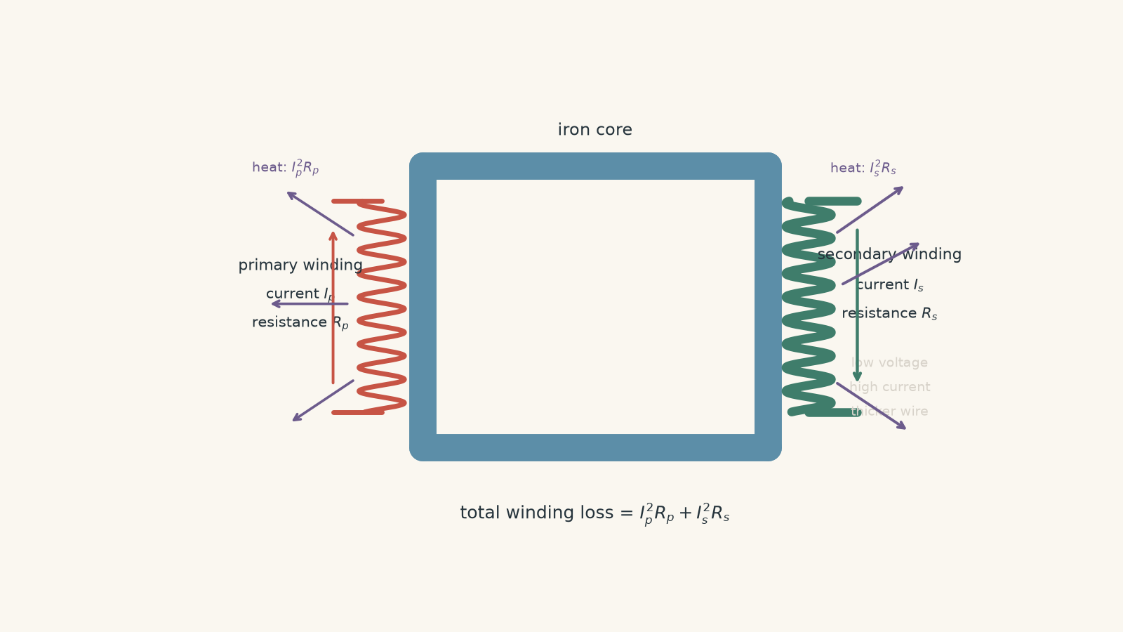
02Both windings contribute to the loss
A practical transformer has resistance in both its primary and secondary windings.
If the primary winding has current \(I_p\) and resistance \(R_p\), its resistive loss is
\[
P_p = I_p^2R_p
\]
If the secondary has current \(I_s\) and resistance \(R_s\), its resistive loss is
\[
P_s = I_s^2R_s
\]
The total winding loss is therefore
\[
P_{\text{winding}} = I_p^2R_p + I_s^2R_s
\]
These losses are often called copper losses because transformer windings are commonly made from copper. The more general term is winding loss, because other conducting materials can also be used.
Picture current as people trying to move through a hallway. Current tells you how many people are passing each second. Resistance tells you how awkward the hallway is to get through.
A packed hallway creates more trouble, but a wider hallway reduces the trouble. That gives the right basic picture: high current tends to increase heating, while low resistance tends to reduce it.
The analogy stops there. It does not explain why heating depends on \(I^2\). The electrical equations do.
03Which winding should get hotter?
Consider a step-down transformer.
If it reduces 240 V to 24 V while transferring roughly the same power, the secondary current must be much larger than the primary current. For an ideal transformer,
\[
V_pI_p = V_sI_s
\]
so
\[
\frac{I_s}{I_p} = \frac{V_p}{V_s}
\]
A 240 V to 24 V transformer therefore has a secondary current about ten times its primary current for the same transferred power.
If the ideal transformer voltage and turns ratio is unfamiliar, it is worth getting that relationship clear before continuing.
You might now predict that the secondary must waste \(10^2=100\) times as much power as the primary.
Not necessarily.
The secondary is normally made from thicker wire, which gives it a much smaller resistance. The whole design problem is a competition between \(I^2\) and \(R\).
For example, suppose
\[
I_p = 1.0\text{ A}, \qquad R_p = 1.5\ \Omega
\]
and
\[
I_s = 10.0\text{ A}, \qquad R_s = 0.015\ \Omega
\]
Then
\[
P_p = (1.0)^2(1.5) = 1.5\text{ W}
\]
while
\[
P_s = (10.0)^2(0.015) = 1.5\text{ W}
\]
The secondary carries ten times the current, yet both windings dissipate the same power.
So there is no reliable rule saying that the high-current winding must produce more heat. Calculate \(I^2R\) for each winding.
04What controls winding resistance?
For a uniform conductor, a useful model is
\[
R = \rho\frac{L}{A}
\]
where:
- \(R\) is resistance in ohms,
- \(\rho\) is the resistivity of the conductor,
- \(L\) is the conductor length, and
- \(A\) is its cross-sectional area.
This immediately gives several practical ways to reduce winding resistance.
| Change | Effect if other quantities stay constant |
|---|---|
| Use a material with lower resistivity | Decreases \(R\) |
| Increase wire cross-sectional area | Decreases \(R\) |
| Reduce unnecessary conductor length | Decreases \(R\) |
| Increase current | Does not change \(R\) directly, but increases \(I^2R\) heating strongly |
| Allow a metal winding to become hotter | Usually increases its resistance |
At HSC level, \(R=\rho L/A\) is the useful model. Real AC windings can have additional effects that make their effective resistance somewhat different from their simple DC resistance, but these effects are not normally needed for HSC transformer questions.
05Why thicker wire helps so much
Suppose a winding carries 8.0 A and has resistance \(0.20\ \Omega\).
Its heating loss is
\[
P_{\text{loss}} = (8.0)^2(0.20) = 12.8\text{ W}
\]
Now imagine the wire cross-sectional area is doubled without changing its material or length.
Because
\[
R \propto \frac{1}{A}
\]
doubling \(A\) halves the resistance:
\[
R_{\text{new}} = 0.10\ \Omega
\]
If the current remains 8.0 A,
\[
P_{\text{loss,new}} = (8.0)^2(0.10) = 6.4\text{ W}
\]
The winding loss has been halved.
This is why high-current windings need thick conductors. A thin wire carrying a large current would have both a substantial \(I\) and a substantial \(R\), which is exactly the combination a transformer designer wants to avoid.
There is a practical limit, of course. Thicker wire takes up more space, uses more material, adds mass, and costs more. Transformer design is not simply a competition to install the chunkiest possible copper noodle.
06Why you cannot just remove turns
Another tempting idea is to shorten the wire by using fewer turns.
Fewer turns means less wire, so the resistance falls. That sounds like an easy efficiency improvement.
But the number of turns is doing another job.
The induced emf depends on the number of turns and the changing magnetic flux. In simplified form,
\[
|\mathcal{E}| = N\left|\frac{\Delta\Phi}{\Delta t}\right|
\]
where \(N\) is the number of turns and \(\Phi\) is magnetic flux.
If the applied primary voltage and frequency stay fixed while \(N\) is reduced, the magnetic flux must change more strongly during each cycle to produce the required emf. That can push the core towards magnetic saturation and increase other losses.
So reducing winding resistance by simply removing turns can damage the magnetic design of the transformer.
This is a good example of why transformer efficiency cannot be understood from \(I^2R\) alone. Faraday’s law constrains what you are allowed to change.
07Practical ways to reduce winding losses
For a transformer intended to provide the same useful output, the most direct improvements are these:
- Use a low-resistivity conductor such as copper.
- Use a larger conductor cross-sectional area, especially where the current is large.
- Avoid unnecessary wire length while still maintaining the required number of turns and winding geometry.
- Make electrical joints and connections with low resistance.
- Keep the transformer within its rated current so that \(I^2R\) losses do not rise excessively.
- Manage temperature so that resistance does not increase unnecessarily and insulation remains within safe limits.
Cooling deserves a careful distinction.
A fan or heatsink can make a transformer run cooler. That is valuable because excessive temperature damages insulation, and a cooler metal winding generally has a lower resistance.
But cooling does not make the electrical loss vanish. If a winding is generating 20 W of resistive heat, the cooling system mainly helps transfer that 20 W to the surroundings.
Reducing the resistance would attack the source of the loss more directly.
08Winding loss and transformer efficiency
Transformer efficiency is
\[
\eta = \frac{P_{\text{out}}}{P_{\text{in}}}\times100\%
\]
where \(P_{\text{out}}\) is the useful output power and \(P_{\text{in}}\) is the input power.
Energy conservation gives
\[
P_{\text{in}} = P_{\text{out}} + P_{\text{loss}}
\]
If winding resistance is the only loss being considered,
\[
P_{\text{in}} = P_{\text{out}} + P_{\text{winding}}
\]
so
\[
\eta =
\frac{P_{\text{out}}}
{P_{\text{out}}+P_{\text{winding}}}
\times100\%
\]
If the question also gives core losses or another loss mechanism, those must be added as well.
A common mistake is to subtract a stated loss from \(P_{\text{out}}\). Usually the output power is already the useful power received by the load. The losses are added to it to reconstruct the larger input power.
Worked example: Calculate winding loss and efficiency
A transformer delivers 180 W to a load. The primary current is \(0.75\text{ A}\), and the primary winding resistance is \(2.4\ \Omega\). The secondary current is \(6.0\text{ A}\), and the secondary winding resistance is \(0.050\ \Omega\). Assume winding resistance is the only energy loss. Calculate the total winding loss and the efficiency.
Step 1
\[
P_p = I_p^2R_p
= (0.75)^2(2.4)
= 1.35\text{ W}
\]
Step 2
\[
P_s = I_s^2R_s
= (6.0)^2(0.050)
= 1.80\text{ W}
\]
Notice that the secondary resistance is far smaller, but its larger current makes its loss slightly greater.
Step 3
\[
P_{\text{winding}}
= 1.35 + 1.80
= 3.15\text{ W}
\]
Step 4
\[
P_{\text{in}}
= P_{\text{out}} + P_{\text{winding}}
= 180 + 3.15
= 183.15\text{ W}
\]
Step 5
\[
\eta
= \frac{180}{183.15}\times100\%
= 98.3\%
\]
The transformer converts about \(98.3\%\) of its input power into useful output power in this simplified model. About \(3.15\text{ W}\) is continuously converted into heat in the windings.
Worked example: Does thicker secondary wire make much difference?
A transformer delivers 240 W to a load. At this operating point, the primary current is \(1.05\text{ A}\), the secondary current is \(10.0\text{ A}\), the primary resistance is \(0.80\ \Omega\), and the secondary resistance is \(0.030\ \Omega\). The transformer also has 5.0 W of other losses.
The secondary wire is redesigned with twice the cross-sectional area, so its resistance is halved. Assume the output power and winding currents remain approximately unchanged for this design comparison.
Calculate the efficiency before and after the change.
Step 1
\[
P_p
= (1.05)^2(0.80)
= 0.882\text{ W}
\]
Step 2
\[
P_s
= (10.0)^2(0.030)
= 3.00\text{ W}
\]
Therefore,
\[
P_{\text{winding}}
= 0.882 + 3.00
= 3.882\text{ W}
\]
Step 3
\[
P_{\text{loss,total}}
= 3.882 + 5.0
= 8.882\text{ W}
\]
So
\[
P_{\text{in}}
= 240 + 8.882
= 248.882\text{ W}
\]
and
\[
\eta
= \frac{240}{248.882}\times100\%
\approx 96.4\%
\]
Step 4
Doubling conductor area halves its resistance:
\[
R_{s,\text{new}}
= \frac{0.030}{2}
= 0.015\ \Omega
\]
The new secondary loss is
\[
P_{s,\text{new}}
= (10.0)^2(0.015)
= 1.50\text{ W}
\]
The primary loss is unchanged, so
\[
P_{\text{winding,new}}
= 0.882 + 1.50
= 2.382\text{ W}
\]
Step 5
\[
P_{\text{loss,total,new}}
= 2.382 + 5.0
= 7.382\text{ W}
\]
\[
P_{\text{in,new}}
= 240 + 7.382
= 247.382\text{ W}
\]
\[
\eta_{\text{new}}
= \frac{240}{247.382}\times100\%
\approx 97.0\%
\]
The secondary winding loss was halved, but the transformer’s total losses were not halved because the primary winding and the other 5.0 W of losses are still present. That is why a substantial improvement to one part of a transformer may produce a smaller change in the overall efficiency percentage.
09The misconception to avoid: high current automatically means high loss
High current is dangerous for efficiency because the loss depends on \(I^2\). But high current does not, by itself, tell you how much power is wasted.
Compare these two windings:
- Winding A: \(I=2.0\text{ A}\), \(R=1.0\ \Omega\)
- Winding B: \(I=8.0\text{ A}\), \(R=0.040\ \Omega\)
For A,
\[
P_A=(2.0)^2(1.0)=4.0\text{ W}
\]
For B,
\[
P_B=(8.0)^2(0.040)=2.56\text{ W}
\]
Winding B carries four times the current but loses less power.
The correct decision rule is simple: calculate \(I^2R\). Do not rank winding losses by current or resistance separately.
There is one more subtlety. Saying that halving \(R\) halves \(I^2R\) assumes the current stays constant. In some circuits, changing the winding resistance also changes the current. The final practice question explores exactly that case.
10Questions and solutions
Question 1
A transformer winding has a resistance of \(0.30\ \Omega\) and carries an RMS current of \(2.0\text{ A}\).
Calculate:
a. the power converted into heat in the winding, and
b. the thermal energy produced in 5.0 minutes if the current remains constant.
Solution 1
The winding loses \(1.2\text{ W}\) as heat and produces \(360\text{ J}\) of thermal energy in 5.0 minutes.
The governing equation for resistive heating is
\[
P_{\text{loss}}=I^2R
\]
so
\[
P_{\text{loss}}
=(2.0)^2(0.30)
=1.2\text{ W}
\]
For part b, convert 5.0 minutes to seconds:
\[
t=5.0\times60=300\text{ s}
\]
Energy transferred is
\[
E=Pt
=(1.2)(300)
=360\text{ J}
\]
The tempting mistake is to use \(P=IR\). But \(IR\) gives voltage, not power. Once the winding’s resistance and current are known, \(I^2R\) gives the rate at which electrical energy becomes thermal energy.
Question 2
A transformer has the following winding data at a particular load:
\[
I_p=0.60\text{ A}, \qquad R_p=4.0\ \Omega
\]
\[
I_s=6.0\text{ A}, \qquad R_s=0.050\ \Omega
\]
a. Calculate the resistive power loss in each winding and the total winding loss.
b. The load increases so that both winding currents rise by \(20\%\). Assume both resistances remain constant. By what percentage does the total winding loss increase?
Solution 2
The primary loses \(1.44\text{ W}\), the secondary loses \(1.80\text{ W}\), and the original total winding loss is \(3.24\text{ W}\). A \(20\%\) increase in both currents produces a \(44\%\) increase in total winding loss.
For the primary,
\[
P_p
=I_p^2R_p
=(0.60)^2(4.0)
=1.44\text{ W}
\]
For the secondary,
\[
P_s
=I_s^2R_s
=(6.0)^2(0.050)
=1.80\text{ W}
\]
Therefore,
\[
P_{\text{winding}}
=1.44+1.80
=3.24\text{ W}
\]
For part b, each current becomes \(1.20\) times its original value.
Because
\[
P_{\text{loss}}\propto I^2
\]
each winding loss is multiplied by
\[
(1.20)^2=1.44
\]
So the new total loss is
\[
P_{\text{new}}
=(1.44)(3.24)
=4.67\text{ W}
\]
The percentage increase is
\[
\frac{4.67-3.24}{3.24}\times100\%
\approx44\%
\]
A very tempting answer is \(20\%\), because the current increased by \(20\%\). The square in \(I^2R\) is the constraint that changes the result.
Question 3
A 240 V to 12 V transformer delivers 120 W to a load. Use the ideal transformer model to estimate its primary and secondary currents.
The primary winding resistance is \(1.6\ \Omega\), the secondary winding resistance is \(0.010\ \Omega\), and the core loses 3.0 W.
a. Calculate the primary and secondary winding losses.
b. Calculate the transformer’s efficiency using these losses.
c. Explain why the secondary is likely to use much thicker wire than the primary even though its resistance is much smaller.
Solution 3
The primary current is approximately \(0.50\text{ A}\), the secondary current is \(10\text{ A}\), the total winding loss is \(1.40\text{ W}\), and the efficiency is approximately \(96.5\%\). The secondary needs thicker wire because its much larger current would otherwise create excessive \(I^2R\) heating.
For an ideal transformer,
\[
P=VI
\]
On the primary side,
\[
I_p
=\frac{P}{V_p}
=\frac{120}{240}
=0.50\text{ A}
\]
On the secondary side,
\[
I_s
=\frac{120}{12}
=10\text{ A}
\]
The primary winding loss is
\[
P_p
=(0.50)^2(1.6)
=0.40\text{ W}
\]
The secondary winding loss is
\[
P_s
=(10)^2(0.010)
=1.00\text{ W}
\]
Therefore,
\[
P_{\text{winding}}
=0.40+1.00
=1.40\text{ W}
\]
Including the 3.0 W core loss,
\[
P_{\text{loss,total}}
=1.40+3.0
=4.40\text{ W}
\]
Hence,
\[
P_{\text{in}}
=120+4.40
=124.40\text{ W}
\]
and
\[
\eta
=\frac{120}{124.40}\times100\%
\approx96.5\%
\]
The secondary carries twenty times the primary current. If both windings had similar resistance, the secondary’s resistive heating would be enormous because of the \(I^2\) dependence.
Using much thicker secondary wire lowers \(R_s\). This is why the secondary can have a much smaller resistance despite carrying much more current.
The tempting shortcut is to say that the primary has the greater resistance, so it must lose more power. The actual comparison is \(I^2R\), not \(R\) alone.
Question 4
A transformer has 1200 primary turns and 120 secondary turns and operates from a 240 V AC supply at a fixed frequency.
A designer proposes reducing both windings by \(25\%\), giving 900 primary turns and 90 secondary turns. The turns ratio is still \(10:1\). Assume, as a first approximation, that each winding’s wire length and resistance would also fall by \(25\%\).
A student argues:
The voltage ratio stays the same and both resistances fall, so the new transformer must be more efficient.
a. Explain why keeping the same turns ratio does not make this conclusion valid.
b. By what factor must the rate of change of magnetic flux increase if the primary is still supplied with 240 V at the same frequency?
c. What primary voltage would approximately preserve the original magnetic-flux behaviour with 900 primary turns?
d. Explain why this redesign therefore does not provide a free reduction in winding loss.
Solution 4
The student’s conclusion is not valid: reducing both turn counts preserves the voltage ratio, but it changes the volts per turn and therefore the required magnetic flux in the core. The rate of change of flux would have to increase by a factor of \(4/3\), and about 180 V rather than 240 V would be required to preserve the original flux behaviour.
The student’s tempting route is to focus only on resistance:
\[
R=\rho\frac{L}{A}
\]
If wire length falls by \(25\%\), then, under the stated approximation,
\[
R_{\text{new}}=0.75R_{\text{old}}
\]
That would indeed reduce \(I^2R\) loss if the current stayed similar.
But the winding also has to satisfy Faraday’s law. In simplified form,
\[
|\mathcal{E}|
=
N\left|\frac{\Delta\Phi}{\Delta t}\right|
\]
Originally,
\[
240
\propto
1200\left|\frac{\Delta\Phi}{\Delta t}\right|_{\text{old}}
\]
After the redesign,
\[
240
\propto
900\left|\frac{\Delta\Phi}{\Delta t}\right|_{\text{new}}
\]
Dividing gives
\[
\frac{
\left|\frac{\Delta\Phi}{\Delta t}\right|_{\text{new}}
}{
\left|\frac{\Delta\Phi}{\Delta t}\right|_{\text{old}}
}
=
\frac{1200}{900}
=
\frac{4}{3}
\]
So the required rate of change of flux is about \(33\%\) larger.
That increased magnetic flux can increase core losses and may push the core towards saturation. Saturation can cause a large magnetising current, creating still more winding heating.
For part c, if the number of primary turns is reduced to \(75\%\) of its original value, the applied voltage must also be reduced to approximately \(75\%\) to preserve the original volts per turn:
\[
V_{\text{new}}
=(0.75)(240)
=180\text{ V}
\]
But with the same \(10:1\) turns ratio, a 180 V primary supply would ideally produce only
\[
V_s=\frac{180}{10}=18\text{ V}
\]
rather than the original 24 V.
That is the exact constraint the simple resistance argument misses. Removing turns can reduce conductor resistance, but those turns are required to produce the correct induced emf without demanding excessive magnetic flux from the core.
The redesign might reduce one loss while worsening another. Overall efficiency therefore cannot be declared higher from the resistance change alone.
Question 5
Model the secondary side of a transformer as an ideal 24 V RMS induced emf in series with a winding resistance of \(0.40\ \Omega\). It supplies a purely resistive \(2.0\ \Omega\) load.
Ignore primary and core losses.
A designer doubles the cross-sectional area of the secondary winding, reducing its resistance from \(0.40\ \Omega\) to \(0.20\ \Omega\).
A student predicts that the winding loss must exactly halve because \(P_{\text{loss}}=I^2R\).
a. Calculate the original secondary current, winding loss, load power, and efficiency.
b. Calculate the same quantities after the winding resistance is reduced.
c. Does the winding loss exactly halve? Explain why the student’s reasoning fails.
d. Explain why the transformer nevertheless becomes more efficient in this model.
Solution 5
The winding loss falls from \(40\text{ W}\) to about \(23.8\text{ W}\), not to \(20\text{ W}\), because reducing the winding resistance also increases the circuit current. The efficiency rises from \(83.3\%\) to \(90.9\%\).
Initially, the ideal induced emf of 24 V drives current through both the winding resistance and the load resistance.
The total resistance is
\[
R_{\text{total}}
=2.0+0.40
=2.40\ \Omega
\]
so the current is
\[
I
=\frac{V}{R_{\text{total}}}
=\frac{24}{2.40}
=10.0\text{ A}
\]
The original winding loss is
\[
P_{\text{winding}}
=I^2r
=(10.0)^2(0.40)
=40\text{ W}
\]
where \(r\) is the secondary winding resistance.
The useful load power is
\[
P_{\text{load}}
=I^2R_L
=(10.0)^2(2.0)
=200\text{ W}
\]
The power supplied by the ideal secondary emf is therefore
\[
P_{\text{in}}
=200+40
=240\text{ W}
\]
and the efficiency of this simplified secondary model is
\[
\eta
=\frac{200}{240}\times100\%
=83.3\%
\]
After the winding area is doubled,
\[
r_{\text{new}}=0.20\ \Omega
\]
The total resistance becomes
\[
R_{\text{total,new}}
=2.0+0.20
=2.20\ \Omega
\]
so the new current is
\[
I_{\text{new}}
=\frac{24}{2.20}
\approx10.91\text{ A}
\]
The new winding loss is
\[
P_{\text{winding,new}}
=(10.91)^2(0.20)
\approx23.8\text{ W}
\]
The new useful load power is
\[
P_{\text{load,new}}
=(10.91)^2(2.0)
\approx238\text{ W}
\]
Therefore,
\[
P_{\text{in,new}}
\approx238+23.8
=261.8\text{ W}
\]
and
\[
\eta_{\text{new}}
=
\frac{238}{261.8}\times100\%
\approx90.9\%
\]
The student’s prediction of exactly \(20\text{ W}\) quietly assumes that \(I\) stays at \(10.0\text{ A}\):
\[
(10.0)^2(0.20)=20\text{ W}
\]
But the current is not fixed here. Reducing the winding resistance reduces the total circuit resistance, which increases the current to about \(10.91\text{ A}\). The larger current partly offsets the benefit of the smaller resistance.
This is an important limit on the shortcut “halve \(R\), halve \(I^2R\)”. It is only exact when \(I\) remains unchanged.
Even so, the fraction of the secondary power wasted inside the winding falls. More of the induced emf appears across the useful load rather than across the winding resistance, so the efficiency rises.
This same habit of separating the useful transfer of energy from each loss mechanism becomes important when you move beyond winding resistance. A real transformer can also lose efficiency through effects such as leakage flux and losses in the magnetic core. The useful next step is to analyse those mechanisms separately rather than treating every missing watt as the same kind of loss.