
Magnetic Field Lines Around Permanent Magnets: HSC Physics
Learn how to draw and interpret magnetic field patterns around bar magnets and multiple magnets, including direction, field strength, and neutral points.
Put a small compass near the north pole of a bar magnet and its needle turns. Move the compass around the magnet and the needle keeps changing direction. Nothing visible is touching the compass, so how do we record what the magnet is doing in the space around it?
Magnetic field lines solve that problem. They give us a map of both the direction of a magnetic field and, approximately, its relative strength. The important skill is not memorising one curved pattern. It is being able to draw and interpret the pattern when magnets are moved, flipped, or combined.
Before reading on, predict this: if you place the north poles of two identical bar magnets facing each other, will the field lines connect straight across the gap?
They won’t. Understanding why is the key to drawing multi-magnet field patterns correctly.
01Start with what a compass actually tells you
Imagine placing lots of tiny compasses around a bar magnet.
At each position, the compass needle settles in a particular direction. If you joined those directions smoothly, you would trace out magnetic field lines.
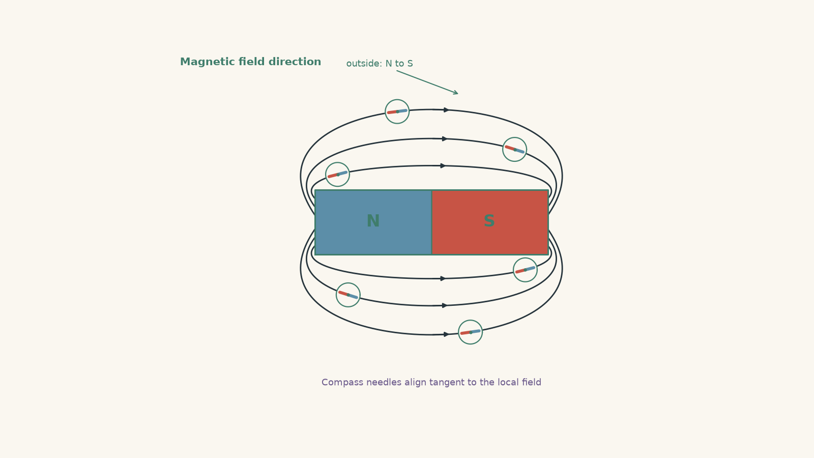
A magnetic field line therefore tells you two things:
- the tangent to the line gives the magnetic field direction at that point
- the spacing of neighbouring lines indicates relative field strength, with closer lines representing a stronger field
The direction of the magnetic field is defined as the direction in which the north pole of a tiny test compass would point.
That convention explains an important rule:
Outside a permanent magnet, magnetic field lines point from north to south.
So for a bar magnet, arrows leave the north pole, curve through the surrounding space, and enter the south pole.
If you want a fuller explanation of why magnets attract or repel once their fields overlap, see Forces Between Magnets: Attraction, Repulsion and Fields.
02Magnetic field lines form closed loops
There is one detail that simplified school diagrams sometimes hide.
A field line does not really start at the north pole and vanish at the south pole. Magnetic field lines form closed loops.
Outside the magnet:
\[ \text{N} \rightarrow \text{S} \]
Inside the magnet:
\[ \text{S} \rightarrow \text{N} \]
That closes the loop.
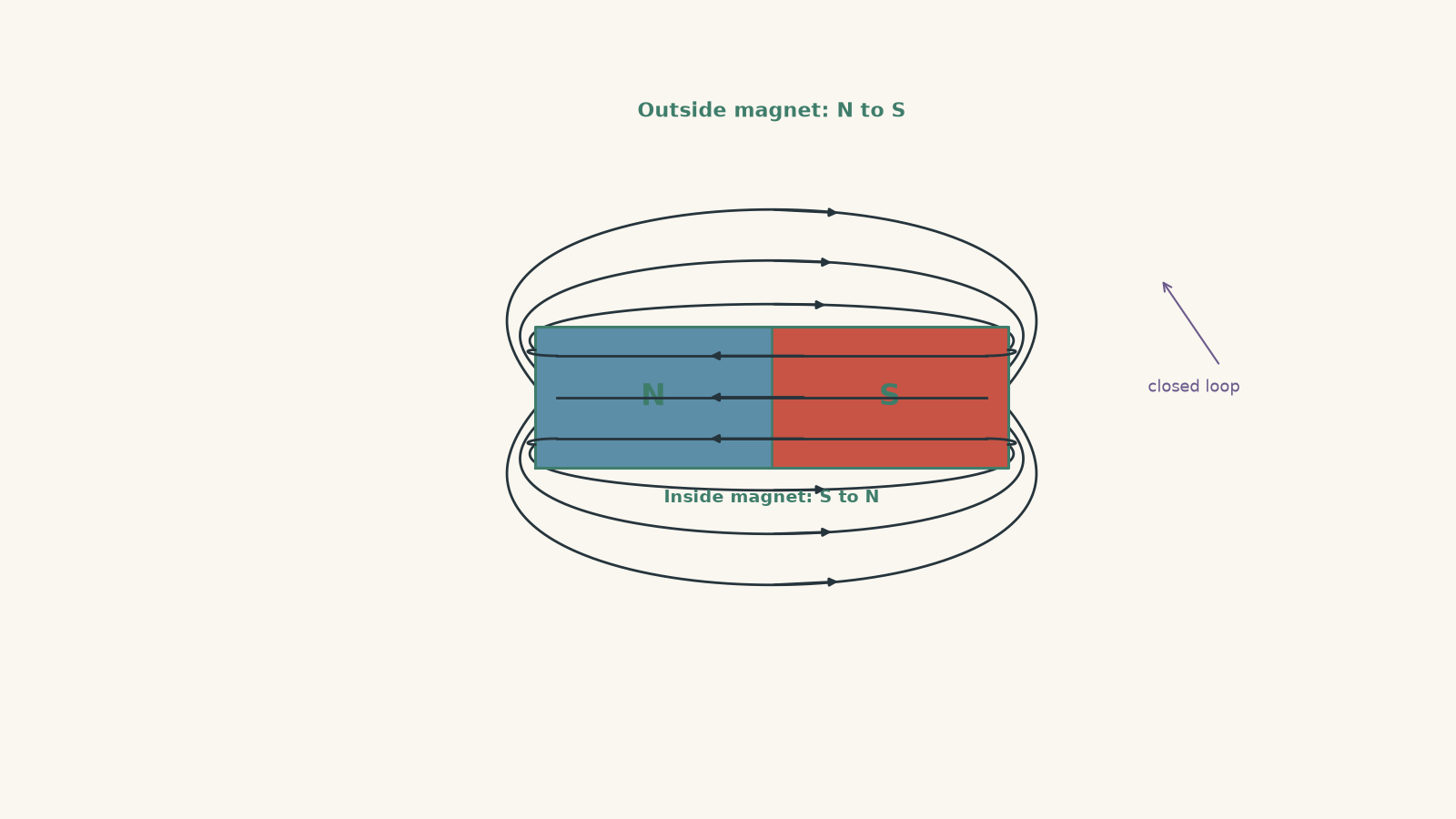
This matters because permanent magnets do not behave as though isolated north and south magnetic poles are sitting separately in space. A normal bar magnet always has both poles.
You can picture field lines as the contour lines on a map, with one important difference: the arrows also tell you which way a compass would point. The analogy is useful because a drawing lets us represent an invisible field. It breaks down if you imagine the lines as actual strings or tubes. There is magnetic field throughout the region, not only on the drawn lines.
03The four rules that make a field-line diagram useful
When drawing magnetic field patterns around permanent magnets, use these rules.
| Rule | What it means |
|---|---|
| Lines point from N to S outside a magnet | This gives the field direction |
| Lines continue through the magnet from S to N | Magnetic field lines form closed loops |
| Lines are closer together where the field is stronger | Field strength is usually greatest near the poles |
| Field lines never cross | The magnetic field at one point cannot have two different directions |
The last rule is especially useful.
Suppose two drawn field lines cross. At the crossing point, one line might say the field points north-east while another says it points south-east. A compass placed at one exact point cannot point both ways at once.
So crossing field lines are not just an ugly sketch. They represent an impossible magnetic field.
04Worked example: Draw the field around one bar magnet
A bar magnet lies horizontally with its north pole on the left and its south pole on the right. Describe how a correct magnetic field-line diagram should be drawn.
Step 1
Draw several lines emerging from the north pole and curving around the outside of the magnet towards the south pole.
Step 2
Place arrowheads on the external lines pointing
\[ \text{N} \rightarrow \text{S}. \]
A compass placed anywhere along one of these lines would point in the direction of the arrow.
Step 3
Draw the field lines more closely spaced near the two poles. This represents the stronger magnetic field in those regions.
Step 4
The lines should curve continuously. They should not suddenly change direction or cross one another.
Step 5
The diagram does not mean that the magnetic field exists only on those lines. The selected lines are a way of showing the direction and relative strength of a continuous magnetic field.
05What changes when there is more than one magnet?
With two magnets, there is not a separate field for each magnet occupying its own private patch of space. At every point, the magnetic effects of the magnets combine.
In more formal language, magnetic field is a vector quantity. If two magnets create fields \(\vec B_1\) and \(\vec B_2\) at the same point, the total field is
\[ \vec B_{\text{total}} = \vec B_1 + \vec B_2. \]
Here, \(\vec B\) represents magnetic field, including both its magnitude and direction.
You do not normally need to calculate those vectors numerically when sketching HSC permanent-magnet field patterns. But the vector idea explains the shape of the lines.
At each point, the line follows the direction of the resultant field.
06Opposite poles facing each other
Put a north pole opposite a south pole.
What would you expect the field to do in the gap?
Because external field lines leave N and enter S, the fields from the two magnets generally point in the same overall direction between the facing poles.
The result is a region containing many fairly direct field lines running from the north pole to the south pole.
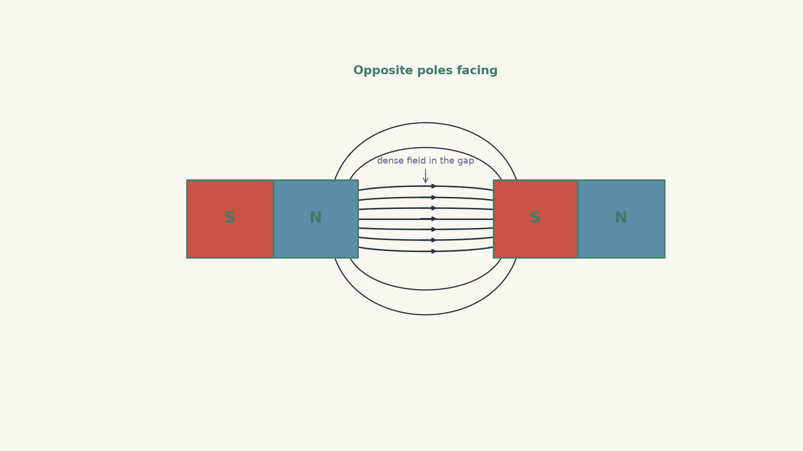
The close spacing tells you something important: the magnetic field in the gap is relatively strong.
This pattern is associated with attraction, but be careful with the logic. Field lines are not elastic bands physically pulling the magnets together. They are a representation of the magnetic field.
07Like poles facing each other
Now return to the prediction from the beginning.
Place two identical north poles facing each other.
A common first guess is that the field lines will join across the gap because “field lines connect magnets”. That feels reasonable if you have memorised the opposite-pole picture rather than the rules.
But field lines outside a magnet must leave a north pole. A line cannot leave one north pole and then enter another north pole.
Instead, the lines emerging from the facing poles bend away from the central region.
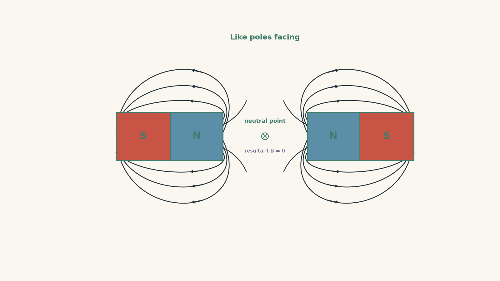
If the magnets are identical and arranged symmetrically, something especially interesting happens at the exact midpoint.
Each magnet produces a field there. The two fields have equal magnitude but opposite directions.
Therefore,
\[ \vec B_{\text{total}} = \vec 0. \]
That location is called a neutral point, meaning the resultant magnetic field is zero there.
Notice what “zero field” means. It does not mean there is no magnetic influence from either magnet. Both magnets produce fields there. Their vector contributions cancel.
That distinction turns up again and again in physics.
08Worked example: Two north poles facing each other
Two identical bar magnets are placed horizontally so that their north poles face one another across a small gap. A student draws several field lines travelling directly from one north pole to the other. Explain what is wrong and describe the correct pattern.
Step 1
Outside a permanent magnet, magnetic field lines leave the north pole. Therefore, both facing north poles have field lines directed outwards into the gap.
Step 2
At the exact midpoint, symmetry means the two magnets produce fields of equal magnitude.
Their directions are opposite.
So the resultant is
\[ \vec B_{\text{total}} = \vec B_1 + \vec B_2 = \vec 0. \]
Step 3
The lines cannot run directly from N to N. Instead, lines emerging from each north pole bend away from the region between them and eventually return to south poles elsewhere on the magnets.
Step 4
The midpoint is a neutral point for this symmetric arrangement. A tiny ideal compass placed exactly there would have no net magnetic field from these magnets telling it which direction to align.
The student’s mistake was treating field lines as connectors between magnets. They are not. Their direction must always agree with the actual resultant magnetic field.
09Field-line density is about field strength, not “number of lines”
Suppose one diagram has ten field lines leaving a magnet and another has twenty.
Does the second diagram automatically represent a magnet twice as strong?
No.
The number of lines drawn is chosen by the person making the diagram. It is not a direct count of physical objects.
What matters within a sensible diagram is the relative spacing. Where the same set of lines bunches closer together, the field is represented as stronger.
This gives you a useful interpretation rule:
Do not count field lines. Compare their local spacing.
For a bar magnet, the field is generally represented as strongest near the poles, where the lines are most densely packed.
10Unequal magnets make the pattern asymmetric
Now imagine two north poles facing each other again, but one magnet is stronger.
Would the neutral point still be halfway between them?
No.
At the midpoint, the stronger magnet would produce the larger field, so the two fields would not cancel.
To get equal opposing field magnitudes, you must move closer to the weaker magnet and farther from the stronger one.
That sounds backwards at first, so picture the goal. The weaker magnet needs help. Moving closer to it strengthens its contribution. At the same time, moving farther from the stronger magnet weakens the stronger contribution.
The cancellation point therefore shifts towards the weaker magnet.
For real bar magnets, the exact position depends on the geometry and magnetic properties of both magnets. The important HSC reasoning is the direction of the shift, not pretending that every magnet follows a simple point-source formula.
11What a field-line diagram lets you predict
Once you can read these diagrams, several questions become much easier.
Which way would a compass point?
Place the compass at the point of interest.
The north end of its needle aligns with the magnetic field, so it points tangent to the field line in the direction of the arrow.
Do not point the compass towards the nearest pole unless the field line actually points that way.
Where is the field stronger?
Look for regions where the field lines are more closely spaced.
For one bar magnet, that is usually near the poles.
For opposite poles facing one another, the gap can contain a particularly strong field because the two fields reinforce one another there.
Where could the resultant field be zero?
Look for a region where field contributions oppose one another.
But opposite direction is not enough. Their magnitudes must also be equal.
That is why symmetry makes neutral points easier to identify.
Can two field lines meet or cross?
They can join smoothly as part of the way a sketch represents a field pattern, but distinct field lines cannot cross at an ordinary point.
A crossing would assign two directions to one magnetic field vector.
12A useful drawing method for unfamiliar arrangements
When several magnets appear in an unfamiliar configuration, do not try to remember a finished picture. Build it.
- Label every north and south pole.
- Mark the rule that external field lines go from N to S.
- Consider the field direction from each magnet in the important regions.
- Ask whether those contributions reinforce or oppose.
- Draw smooth lines that follow the resultant direction.
- Make the lines denser in stronger-field regions.
- Check that no field lines cross.
- Check for symmetry or possible neutral points.
This method is much more reliable than trying to memorise every possible pair of magnets.
13The misconception to avoid: field lines show the path of a moving particle
A field line is not automatically the path followed by an object.
That distinction is easy to miss because arrows often look like motion.
A magnetic field line tells you the direction of the magnetic field. A small compass aligns with it, but the motion of a charged particle is a different question. For a moving electric charge, the magnetic force depends on both the magnetic field and the particle’s velocity.
So when you later study charged particles in magnetic fields, do not treat field lines as railway tracks.
For permanent magnets, think of them as a direction map, not a collection of physical paths.
14Questions and solutions
Question 1
A bar magnet is placed horizontally with N on the left and S on the right. A compass is positioned above the centre of the magnet.
In a correctly drawn field pattern, approximately which way does the north end of the compass needle point?
Solution 1
The north end points generally from left to right, following the external field from N towards S.
Outside a permanent magnet, magnetic field lines run from the north pole to the south pole. Above the centre of the magnet, the field line curves from the left-hand N pole towards the right-hand S pole.
The compass needle aligns tangent to that field line.
The trap is to assume that the compass must point directly towards the nearest pole. A compass responds to the local magnetic field direction, not simply to which pole is closest.
Question 2
Two identical bar magnets are placed with a north pole of one facing the south pole of the other.
A student says, “The field between the magnets must be weak because the two magnets pull in opposite directions.”
Explain whether the statement is correct.
Solution 2
The statement is incorrect. The magnetic fields between the facing N and S poles generally reinforce one another, producing a relatively strong field in the gap.
External magnetic field points away from the facing north pole and towards the facing south pole. These directions are the same across much of the gap.
The resultant field is therefore the vector sum
\[ \vec B_{\text{total}} = \vec B_1 + \vec B_2, \]
and the two contributions reinforce rather than cancel.
A field-line diagram represents this using closely spaced lines connecting the N pole to the S pole.
The misconception comes from mixing up forces on the magnets with directions of the magnetic fields. The magnets attract, but that does not mean their fields must oppose between them.
Question 3
Two identical magnets have their north poles facing each other. Point P is exactly halfway between the two north poles.
State the resultant magnetic field at P and explain what causes it.
Solution 3
The resultant magnetic field at P is zero, assuming the magnets and arrangement are perfectly symmetric.
Each magnet produces a magnetic field at P. Because P is equally far from two identical, symmetrically arranged poles, the field magnitudes are equal.
Their directions are opposite because the field points away from each north pole.
Therefore,
\[ \vec B_{\text{total}} = \vec B_1 + \vec B_2 = \vec 0. \]
P is a neutral point.
The important idea is that neither magnet’s field is individually zero at P. The resultant is zero because two non-zero vectors cancel.
Question 4
A student sketches two magnetic field lines that cross between a pair of bar magnets. They argue that this is possible because each line belongs to a different magnet.
Explain the flaw in this reasoning.
Solution 4
The field lines cannot cross, even if more than one magnet produces the field.
At any point in space, the fields due to all magnets combine to form one resultant magnetic field vector:
\[ \vec B_{\text{total}} = \vec B_1 + \vec B_2 + \cdots \]
That resultant has one definite direction at the point.
If two field lines crossed, their tangents at the crossing would usually point in different directions. The diagram would therefore claim that the magnetic field has two directions at one position, which is impossible.
The student’s mistake is treating each magnet as having an independent set of field lines that can pass through one another. Once the fields overlap, we represent the single resultant field, not separate overlapping direction maps.
Question 5
Two bar magnets have north poles facing each other. The magnet on the left produces a stronger magnetic field than the magnet on the right.
A neutral point exists somewhere along the line between the facing poles.
Is the neutral point closer to the stronger magnet, closer to the weaker magnet, or exactly halfway between them? Explain.
Solution 5
The neutral point is closer to the weaker magnet.
For the resultant field to be zero, the opposing field magnitudes must be equal:
\[ B_{\text{left}} = B_{\text{right}}. \]
If the left magnet is stronger, then at equal distances it produces the larger field.
The cancellation point must therefore shift away from the stronger magnet and towards the weaker magnet. Moving towards the weaker magnet increases its field contribution, while moving away from the stronger magnet decreases the stronger contribution.
Eventually the two opposing fields can have equal magnitudes.
The tempting mistake is to move the neutral point towards the stronger magnet because it seems like the stronger magnet should “pull” the neutral point towards itself. But the neutral point is not an object being pulled. It is simply the location where two field vectors happen to cancel.
Question 6
Two identical bar magnets are initially arranged with opposite poles facing each other across a gap. One magnet is then rotated by \(180^\circ\), so that the same poles now face each other.
A student claims that the only necessary change to the original field-line diagram is to reverse the arrows on the lines in the gap.
Explain why this cannot produce the correct new field pattern.
Solution 6
Reversing the arrows is not enough because rotating the magnet changes the direction of one magnet’s field, which changes the shape of the resultant field throughout the region.
With opposite poles facing, external field lines can run from the facing N pole towards the facing S pole. The field contributions in much of the gap reinforce, so lines can pass densely through that region.
After one magnet is rotated, like poles face one another. If they are north poles, both produce fields directed away from themselves in the gap. Those contributions oppose along the central line.
For identical magnets, they cancel at the midpoint:
\[ \vec B_{\text{total}} = \vec 0. \]
The surrounding resultant field directions also change. Field lines must therefore bend away from the central region rather than continuing straight across it.
Simply reversing arrowheads would leave the old geometric pattern in place, but a field-line diagram must show both direction and shape of the resultant field.
This is the deeper reason field patterns are worth understanding rather than memorising. Once you can combine magnetic field directions and recognise reinforcement, cancellation, and symmetry, you have the basis for analysing magnetic forces, current-carrying conductors, and moving charged particles in magnetic fields.