
Magnetic Field Inside a Solenoid: HSC Physics Explained
Learn how to determine the direction and strength of the magnetic field inside an ideal solenoid using right-hand rules and B = μ₀NI/L.
A single loop of wire carrying current produces a magnetic field, but that field spreads out through space. Now wind the wire into hundreds of closely spaced loops. What happens to the field in the middle?
Before reading on, make a prediction: do the fields from neighbouring loops mostly cancel inside the coil, or reinforce each other?
They reinforce. That is the useful trick behind a solenoid. By arranging many current-carrying loops in a row, we can produce a strong magnetic field that is approximately uniform through most of the coil’s interior.
The two HSC skills you need are closely connected:
- work out the direction of the magnetic field using a right-hand rule
- calculate the magnitude of the field using \(B = \mu_0 NI/L\)
The formula is short. The harder part is knowing why it works, what each quantity means, and when you are allowed to use it.
01From one loop to a solenoid
Start with one current-carrying wire. Current produces a magnetic field that circles the wire. If you need to refresh that idea first, see Magnetic Field Around a Current-Carrying Wire: HSC Physics.
Now bend the wire into a circular loop. The magnetic field still circles every small section of wire, but something useful happens near the centre of the loop: those individual field contributions point mostly in the same direction.
Add another loop beside it. Then another. Then a few hundred.
A solenoid is essentially many loops cooperating.
You can picture each turn as making its own contribution to the total magnetic field. Inside a long, tightly wound solenoid, these contributions largely reinforce one another. Outside, contributions from different sections point in competing directions and largely cancel.
That is why the field pattern looks roughly like this:
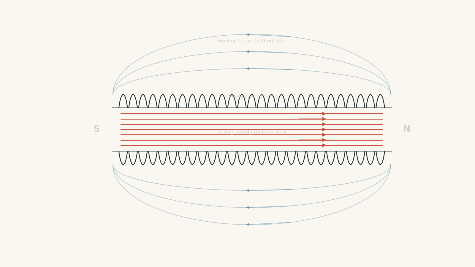
The field inside is strongest and approximately uniform away from the ends. The field outside an ideal solenoid is treated as zero.
That last statement is an idealisation. A real solenoid has a weak external field, especially near its ends.
02Why the inside field is approximately uniform
Look at the middle of a long solenoid.
There are turns to your left and turns to your right. Because the turns are closely spaced and repeat the same geometry, the combined magnetic field has almost the same strength and direction at nearby points along the interior.
The field lines there are therefore drawn:
- straight
- parallel
- evenly spaced
Those features represent an approximately uniform magnetic field.
Near an end, the situation changes. There are no more turns beyond the end to provide the same symmetrical contribution, so the field starts to spread out.
This gives an important decision rule:
Use the ideal solenoid model for points well inside a long, tightly wound solenoid. Be cautious near the ends.
The same idea explains why a shorter, wider coil behaves less like an ideal solenoid. End effects become more important.
03Finding the magnetic field direction
The solenoid’s direction comes from the direction of conventional current.
Conventional current is defined as the direction positive charge would move. In a metal wire, electrons actually drift the other way. HSC direction rules use conventional current unless the question explicitly says otherwise.
There are two useful versions of the right-hand rule.
Method 1: curl your fingers with the current
Wrap the fingers of your right hand around the solenoid so that your fingers curl in the direction of conventional current around the turns.
Your thumb points:
- in the direction of the magnetic field inside the solenoid
- towards the solenoid’s north pole
Suppose your thumb points to the right. The magnetic field inside the solenoid also points to the right, and the right-hand end is the north pole.
This matches the magnetic field pattern of a bar magnet. Inside a magnet or solenoid, the field runs from south to north. Outside, it curves from north back towards south.
For a refresher on this field-line convention, see Magnetic Field Lines Around Permanent Magnets: HSC Physics.
Method 2: look directly at one end
Sometimes the diagram shows the current as viewed from the end of the solenoid.
Use this shortcut:
| Current around the end you are viewing | That end is |
|---|---|
| Anticlockwise | North |
| Clockwise | South |
Why?
If the current looks anticlockwise to you, curl the fingers of your right hand anticlockwise. Your thumb points towards you. The field inside therefore points towards that end, making it the north end.
If the current looks clockwise, your thumb points away from you. The field inside points away from that end, so that end is south.
The most common direction mistake
A student sees electron motion marked on the wire and immediately applies the right-hand rule in that direction.
That feels reasonable. After all, the electrons are the charges actually moving.
But the standard right-hand rule is defined using conventional current, which runs opposite to electron motion in a metal.
So if electron flow is shown, reverse it first.
04Calculating the field inside an ideal solenoid
For an ideal air-core solenoid,
\[ B = \frac{\mu_0 NI}{L} \]
where:
- \(B\) is the magnetic flux density inside the solenoid, measured in tesla (\(\text{T}\))
- \(\mu_0\) is the permeability of free space, \(4\pi \times 10^{-7}\ \text{T m A}^{-1}\)
- \(N\) is the total number of turns
- \(I\) is the current through the solenoid, measured in amperes (\(\text{A}\))
- \(L\) is the length of the solenoid, measured in metres (\(\text{m}\))
You will sometimes see the equation written as
\[ B = \mu_0 nI \]
where
\[ n = \frac{N}{L} \]
and \(n\) is the number of turns per metre.
These are not two different formulas. They are the same relationship written in different forms.
05What the equation is really saying
Do not treat \(B = \mu_0 NI/L\) as four letters to substitute into.
It tells you how the field changes.
More current gives a stronger field
If \(N\) and \(L\) stay constant,
\[ B \propto I \]
Double the current and the field doubles.
That makes physical sense. Each turn produces a stronger magnetic field, so their combined field is stronger.
More turns gives a stronger field
If \(I\) and \(L\) stay constant,
\[ B \propto N \]
Double the number of turns packed into the same length and the field doubles.
You have doubled the number of field-producing loops per unit length.
Increasing the length can weaken the field
If \(N\) and \(I\) stay constant,
\[ B \propto \frac{1}{L} \]
Stretching the same \(N\) turns over a greater length lowers the number of turns per metre.
This is where students often make a bad prediction.
Suppose a 1000-turn solenoid is stretched until it is twice as long, but no turns are added. Does its field stay the same because it still has 1000 turns?
No. The turns are now more spread out. Since \(N/L\) has halved, the ideal magnetic field also halves.
The more fundamental quantity here is the turn density, \(N/L\), not simply the total number of turns.
06Worked example: Calculate the field inside a solenoid
A long air-core solenoid has 800 turns spread evenly over a length of \(0.40\ \text{m}\). It carries a current of \(1.50\ \text{A}\). Calculate the magnetic flux density inside the solenoid.
Step 1
\[ B = \frac{\mu_0 NI}{L} \]
Step 2
\[ \mu_0 = 4\pi \times 10^{-7}\ \text{T m A}^{-1} \]
\[ N = 800,\qquad I = 1.50\ \text{A},\qquad L = 0.40\ \text{m} \]
Step 3
\[ \begin{aligned} B &= \frac{(4\pi \times 10^{-7})(800)(1.50)}{0.40} \\ &= 3.77 \times 10^{-3}\ \text{T} \end{aligned} \]
Step 4
\[ \boxed{B = 3.77 \times 10^{-3}\ \text{T}} \]
So the field inside the ideal solenoid is about \(3.77\ \text{mT}\), where \(\text{mT}\) means millitesla.
07Worked example: What happens when a solenoid is stretched?
A long air-core solenoid has 900 turns and initially has a length of \(0.45\ \text{m}\). It carries a constant current of \(2.00\ \text{A}\). The solenoid is stretched uniformly until its length is \(0.75\ \text{m}\), without changing the number of turns or the current. Calculate the magnetic field before and after stretching, and determine the percentage decrease.
Step 1
\[ \begin{aligned} B_1 &= \frac{\mu_0 NI}{L_1} \\ &= \frac{(4\pi \times 10^{-7})(900)(2.00)}{0.45} \\ &= 5.03 \times 10^{-3}\ \text{T} \end{aligned} \]
The initial field is
\[ B_1 = 5.03\ \text{mT} \]
Step 2
The number of turns and current have not changed. Only the length has changed.
\[ \begin{aligned} B_2 &= \frac{\mu_0 NI}{L_2} \\ &= \frac{(4\pi \times 10^{-7})(900)(2.00)}{0.75} \\ &= 3.02 \times 10^{-3}\ \text{T} \end{aligned} \]
So
\[ B_2 = 3.02\ \text{mT} \]
Step 3
\[ \begin{aligned} \text{percentage decrease} &= \frac{B_1-B_2}{B_1}\times100\% \\ &= \frac{5.03-3.02}{5.03}\times100\% \\ &\approx 40.0\% \end{aligned} \]
The magnetic field decreases by about
\[ \boxed{40.0\%} \]
Stretching the solenoid reduces its turn density from \(900/0.45 = 2000\) turns per metre to \(900/0.75 = 1200\) turns per metre. That reduction in turn density is why the field becomes weaker.
08What “ideal solenoid” is hiding
The equation
\[ B = \frac{\mu_0 NI}{L} \]
does not describe every coil perfectly.
The ideal model assumes that the solenoid is:
- long compared with its diameter
- tightly and evenly wound
- carrying the same current through every turn
- being considered well away from its ends
- air-cored or effectively in free space when \(\mu_0\) is used
Under those conditions, we treat the interior field as uniform and the exterior field as approximately zero.
A real solenoid breaks those assumptions to some extent.
For example, near an open end, magnetic field lines spread out. The field there is not equal to the uniform central value predicted by the simple formula.
This is similar to calling a road “flat” over a short section. The approximation can be extremely useful, but it does not mean every point on the actual road has exactly the same height.
09A tempting misconception: more turns always means a stronger field
Imagine two ideal solenoids carrying the same current.
- Solenoid A has 500 turns over \(0.25\ \text{m}\).
- Solenoid B has 1000 turns over \(0.50\ \text{m}\).
Which has the stronger field?
It is tempting to choose B because it has twice as many turns.
But calculate the turn density:
\[ \frac{N_A}{L_A} = \frac{500}{0.25} = 2000\ \text{m}^{-1} \]
and
\[ \frac{N_B}{L_B} = \frac{1000}{0.50} = 2000\ \text{m}^{-1} \]
They have the same \(N/L\).
If their currents are also equal, the ideal magnetic fields are equal.
This is a useful general habit in physics: when a formula contains a ratio, changing the numerator alone is not enough information. You must check whether the denominator changed too.
10Direction and magnitude are separate jobs
A numerical value for \(B\) tells you the field’s magnitude, not its direction.
For example,
\[ B = 4.0 \times 10^{-3}\ \text{T} \]
does not tell you whether the field points left or right through the solenoid.
You normally need two steps:
- Use the current direction and a right-hand rule to determine the field direction.
- Use \(B = \mu_0 NI/L\) to calculate the field magnitude.
Do not try to put a negative current into the equation just because the field points left in a diagram. At HSC level, it is usually clearer to calculate the positive magnitude of \(B\), then state the direction separately.
11Questions and solutions
Question 1
A long air-core solenoid contains 600 turns over a length of \(0.30\ \text{m}\) and carries a current of \(1.20\ \text{A}\).
Calculate the magnetic flux density inside the solenoid. When viewed from its right-hand end, the conventional current flows anticlockwise around the turns. State the direction of the field inside the solenoid.
Solution 1
The magnetic field is \(\boxed{3.02 \times 10^{-3}\ \text{T}}\), directed towards the right-hand end of the solenoid.
For an ideal solenoid,
\[ B = \frac{\mu_0 NI}{L} \]
Substituting,
\[ \begin{aligned} B &= \frac{(4\pi \times 10^{-7})(600)(1.20)}{0.30} \\ &= 3.02 \times 10^{-3}\ \text{T} \end{aligned} \]
So
\[ \boxed{B = 3.02\ \text{mT}} \]
Viewed from the right-hand end, the current is anticlockwise. Curling the fingers of the right hand anticlockwise makes the thumb point towards the observer. The right-hand end is therefore the north end.
Inside the solenoid, the magnetic field points towards that north end, so it points to the right.
Question 2
An ideal solenoid initially has magnetic field strength \(B_0\). Its number of turns remains unchanged, but its length is doubled and its current is tripled.
Determine the new magnetic field strength in terms of \(B_0\).
Solution 2
The new magnetic field is \(\boxed{1.5B_0}\).
The field of an ideal solenoid is
\[ B = \frac{\mu_0 NI}{L} \]
Initially,
\[ B_0 = \frac{\mu_0 NI}{L} \]
After the change,
\[ I' = 3I \]
and
\[ L' = 2L \]
while \(N\) remains unchanged. Therefore,
\[ \begin{aligned} B' &= \frac{\mu_0 N(3I)}{2L} \\ &= \frac{3}{2}\frac{\mu_0 NI}{L} \\ &= 1.5B_0 \end{aligned} \]
Tripling the current would by itself triple the field, but doubling the length halves the turn density. The combined effect is therefore a factor of \(3/2\).
Question 3
Solenoid A has 450 turns spread evenly over \(0.18\ \text{m}\). Solenoid B has 750 turns spread evenly over \(0.30\ \text{m}\). Both are long air-core solenoids carrying \(0.80\ \text{A}\).
A student argues that Solenoid B must produce the stronger magnetic field because it has 300 additional turns.
Determine whether the student is correct and calculate the magnetic field in each solenoid.
Solution 3
The student is incorrect. The two ideal solenoids produce the same magnetic field, \(\boxed{2.51 \times 10^{-3}\ \text{T}}\).
The important quantity is not \(N\) alone. It is the turn density \(N/L\).
For Solenoid A,
\[ \frac{N_A}{L_A} = \frac{450}{0.18} = 2500\ \text{m}^{-1} \]
For Solenoid B,
\[ \frac{N_B}{L_B} = \frac{750}{0.30} = 2500\ \text{m}^{-1} \]
Their turn densities are identical.
For A,
\[ \begin{aligned} B_A &= \frac{\mu_0 N_A I}{L_A} \\ &= (4\pi \times 10^{-7})(2500)(0.80) \\ &= 2.51 \times 10^{-3}\ \text{T} \end{aligned} \]
For B,
\[ \begin{aligned} B_B &= \frac{\mu_0 N_B I}{L_B} \\ &= (4\pi \times 10^{-7})(2500)(0.80) \\ &= 2.51 \times 10^{-3}\ \text{T} \end{aligned} \]
Thus,
\[ \boxed{B_A = B_B = 2.51\ \text{mT}} \]
The trap is focusing on the total number of turns while ignoring the greater length over which Solenoid B’s turns are spread.
Question 4
A long solenoid contains 1200 evenly spaced turns over a length of \(0.60\ \text{m}\). It is divided at its midpoint into two separate solenoids. Each half therefore contains 600 turns over \(0.30\ \text{m}\).
Each new solenoid is connected separately so that it carries the same current as the original solenoid.
Using the ideal solenoid model, compare the magnetic field inside one new half with the field inside the original solenoid. Then explain one reason why the real fields may not be exactly equal.
Solution 4
The ideal model predicts that the magnetic field is unchanged, because the turn density remains the same. In reality, the shorter solenoids may show greater end effects.
Originally,
\[ \frac{N}{L} = \frac{1200}{0.60} = 2000\ \text{m}^{-1} \]
For either half,
\[ \frac{N_{\text{half}}}{L_{\text{half}}} = \frac{600}{0.30} = 2000\ \text{m}^{-1} \]
Since the current is also unchanged,
\[ B_{\text{original}} = \mu_0\left(2000\right)I \]
and
\[ B_{\text{half}} = \mu_0\left(2000\right)I \]
Therefore,
\[ \boxed{B_{\text{half}} = B_{\text{original}}} \]
according to the ideal model.
The tempting mistake is to say that halving the number of turns must halve the field. That ignores the fact that the length was also halved.
For a real solenoid, however, making each coil shorter can make end effects more significant. If the new length is no longer large compared with the coil diameter, the assumption of a uniform interior field becomes less accurate.
Question 5
A coil is constructed from two interleaved sets of turns over the same \(0.40\ \text{m}\) length. One set contains 500 turns carrying \(1.00\ \text{A}\) in a direction that produces a magnetic field to the right. The second set also contains 500 turns carrying \(1.00\ \text{A}\), but its current circulates in the opposite direction.
A student adds the turns together and calculates
\[ B = \frac{\mu_0(1000)(1.00)}{0.40} \]
for the magnetic field.
Explain the flaw in this method and determine the net magnetic field using the ideal-solenoid approximation.
Solution 5
The student’s method is incorrect. The two sets produce equal magnetic fields in opposite directions, so the net field is \(\boxed{0\ \text{T}}\) under the ideal approximation.
The formula \(B = \mu_0 NI/L\) assumes the turns contribute magnetic field in the same direction. Simply counting all 1000 turns ignores the direction of each contribution.
For the first set,
\[ \begin{aligned} B_1 &= \frac{\mu_0 N_1I_1}{L} \\ &= \frac{(4\pi \times 10^{-7})(500)(1.00)}{0.40} \\ &= 1.57 \times 10^{-3}\ \text{T} \end{aligned} \]
This field points to the right.
The second set has the same \(N\), \(I\), and \(L\), so its field has the same magnitude:
\[ B_2 = 1.57 \times 10^{-3}\ \text{T} \]
but it points to the left.
Magnetic fields are vectors, so opposing contributions subtract:
\[ \begin{aligned} B_{\text{net}} &= B_1-B_2 \\ &= 1.57\times10^{-3}-1.57\times10^{-3} \\ &= 0\ \text{T} \end{aligned} \]
Thus,
\[ \boxed{B_{\text{net}} = 0\ \text{T}} \]
The deeper point is that \(N\) is not just a number to count mechanically. The usual solenoid equation works because the turns reinforce one another. If some turns produce fields in the opposite direction, superposition must be considered before using a single total \(N\).
12What this lets you do next
A solenoid brings several magnetic-field ideas together in one clean model.
The right-hand rule tells you which way the field points. The ratio \(N/L\) tells you how densely the turns are packed. The current \(I\) controls how strongly each turn contributes. Together,
\[ B = \frac{\mu_0 NI}{L} \]
gives the field magnitude for an ideal air-core solenoid.
Once you can determine both the magnitude and direction of \(B\), you have the information needed for the next step: predicting what happens when charges or current-carrying conductors are placed in that magnetic field. That is where a solenoid stops being just a coil of wire and becomes a controlled magnetic environment for analysing magnetic forces.