
Torque on a Current-Carrying Coil for HSC Physics
Learn how and why a current-carrying coil experiences torque in a magnetic field, and how to use \ ( \ tau=nIAB \ sin \ theta \ ) correctly in motor problems.
A rectangular coil sits between two magnetic poles. Current flows through it. One side of the coil is pushed up, while the opposite side is pushed down.
If those two magnetic forces are equal and opposite, what should happen: nothing, sideways motion, or rotation?
The net force is zero, so the coil does not accelerate sideways. But the forces act along different lines. Together they produce a turning effect – a torque.
Now make a second prediction. When the flat face of the coil points directly towards the magnetic field, would you expect the torque to be largest? It sounds plausible: the field is going straight through the coil. In fact, the torque is zero there.
Understanding why gives you the motor equation
\[
\tau=nIAB\sin\theta
\]
without having to treat it as a formula to memorise.
01Why equal and opposite forces can still turn something
Imagine trying to twist a stubborn jar lid. Your two hands can push in opposite directions. Their forces can cancel as a net force, yet the lid still turns because the forces act at different positions.
That is a couple: two equal, opposite, parallel forces separated by a distance.
A current-carrying coil in a magnetic field behaves in a similar way. On two opposite sides of the coil, the currents run in opposite directions. The magnetic field therefore produces magnetic forces in opposite directions.
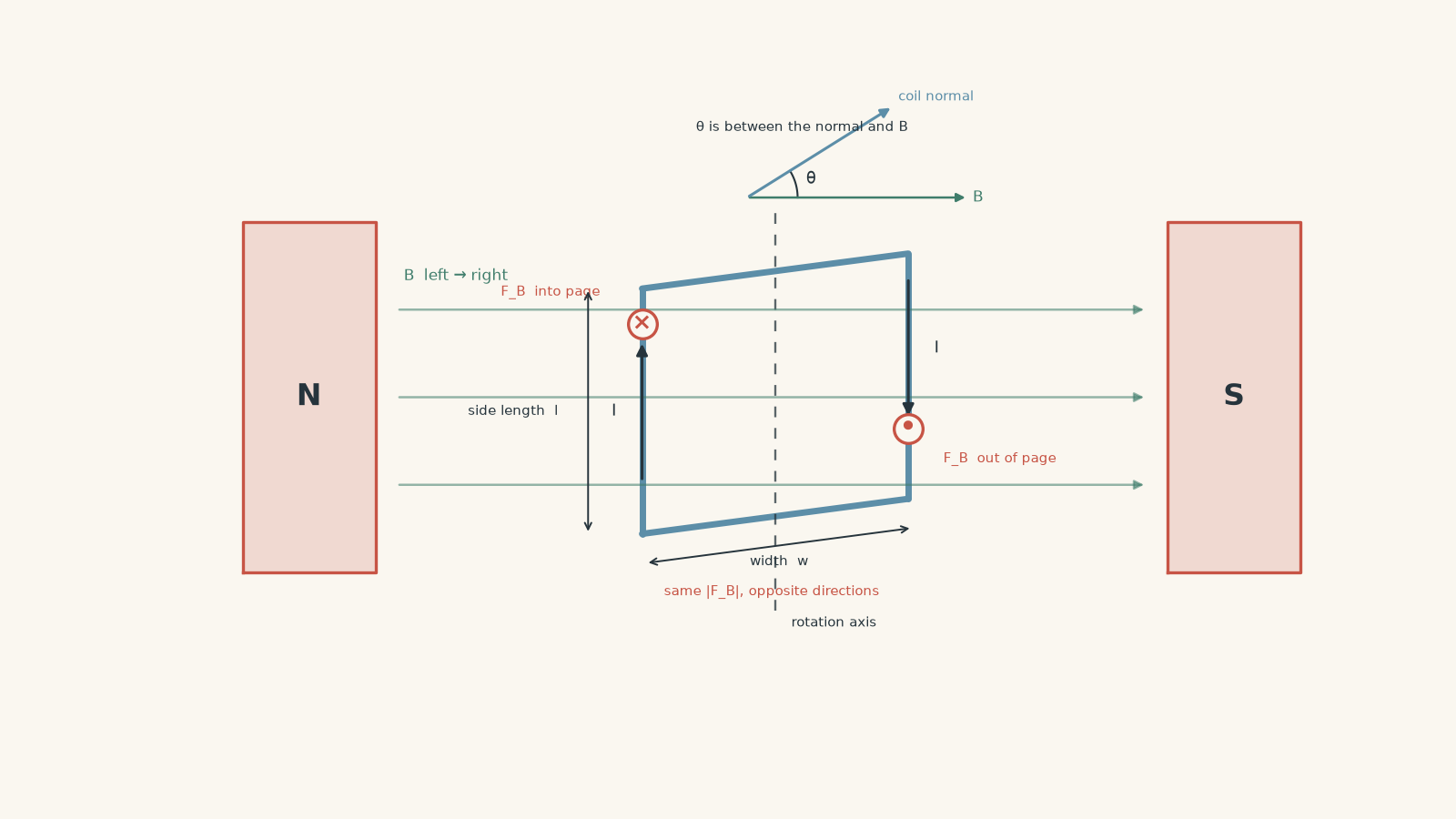
The jar-lid analogy has a limit. You can put your hands wherever you like and choose how to push. In the motor, the force is fixed by the current direction and magnetic field. We need the motor-effect equation to work out exactly what happens.
For a straight conductor of length \(l\) carrying current \(I\) in a magnetic field \(B\),
\[
F=BIl\sin\phi
\]
where \(\phi\) is the angle between the current and the magnetic field.
For the two active sides of a simple rectangular motor coil, the current is perpendicular to the field, so \(\phi=90^\circ\). Therefore,
\[
F=BIl
\]
on each active side.
02From magnetic force to torque
Suppose the rectangular coil has:
- active side length \(l\),
- width \(w\),
- current \(I\), and
- magnetic field strength \(B\).
Each active side experiences a force \(BIl\).
Torque depends on more than force. It also depends on the perpendicular distance between the forces’ lines of action.
For a couple,
\[
\tau=Fd
\]
where \(d\) is that perpendicular separation.
Here is the important geometry. Define \(\theta\) as the angle between the magnetic field and the normal to the plane of the coil.
The normal is an imaginary line sticking straight out of the coil’s flat face.
When the normal makes angle \(\theta\) with the field, the effective separation of the two forces is
\[
d=w\sin\theta
\]
so
\[
\tau=(BIl)(w\sin\theta)
\]
and because the area of the rectangular coil is \(A=lw\),
\[
\tau=IAB\sin\theta
\]
for one turn.
If the coil contains \(n\) identical turns, each turn contributes torque in the same direction:
\[
\boxed{\tau=nIAB\sin\theta}
\]
where:
| Symbol | Meaning | Unit |
|---|---|---|
| \(\tau\) | torque on the coil | N m |
| \(n\) | number of turns | no unit |
| \(I\) | current | A |
| \(A\) | area of one turn | \(\text{m}^2\) |
| \(B\) | magnetic field strength | T |
| \(\theta\) | angle between the coil’s normal and \(B\) | degrees or radians |
The equation gives the magnitude of the torque. Its rotational direction must be found from the directions of the current and magnetic field.
03The angle is the part most students mix up
The \(\theta\) in
\[
\tau=nIAB\sin\theta
\]
is not normally the angle between the plane of the coil and the magnetic field.
It is the angle between the field and the line normal to the coil.
That changes the result completely.
| \(\theta\), normal to field | Position of coil | Torque |
|---|---|---|
| \(0^\circ\) | plane perpendicular to field | \(0\) |
| \(30^\circ\) | tilted | \(0.5\tau_{\max}\) |
| \(90^\circ\) | plane parallel to field | \(\tau_{\max}\) |
| \(180^\circ\) | plane perpendicular to field again | \(0\) |
So maximum torque occurs when
\[
\theta=90^\circ
\]
because \(\sin90^\circ=1\).
Then
\[
\tau_{\max}=nIAB
\]
This is worth picturing rather than memorising. When the plane of the coil is parallel to the field, the two magnetic forces have their greatest effective separation. They have the largest possible lever arm, so they produce the largest torque.
When the plane is perpendicular to the field, the forces still exist on the active sides, but their lines of action have no effective separation about the rotation axis. The torque is zero.
If the question gives the angle of the plane
Suppose the plane of the coil makes an angle \(\alpha\) with the magnetic field.
For angles between \(0^\circ\) and \(90^\circ\),
\[
\theta=90^\circ-\alpha
\]
so
\[
\tau=nIAB\sin(90^\circ-\alpha)
\]
or
\[
\tau=nIAB\cos\alpha
\]
Both equations describe the same physics. The safest approach in an exam is usually to convert the stated angle into the normal-field angle \(\theta\), then use the formula exactly as given.
Worked example: maximum torque on a coil
A 50-turn motor coil carries a current of \(0.80\text{ A}\). Each turn has an area of \(30\text{ cm}^2\) and is in a uniform \(0.25\text{ T}\) magnetic field. Calculate the maximum torque.
Step 1
Maximum torque occurs at \(\theta=90^\circ\), so
\[
\sin\theta=1
\]
Step 2
Because
\[
1\text{ cm}^2=10^{-4}\text{ m}^2
\]
we have
\[
A=30\times10^{-4}=3.0\times10^{-3}\text{ m}^2
\]
Step 3
\[
\begin{aligned}
\tau_{\max}
&=nIAB\\
&=(50)(0.80)(3.0\times10^{-3})(0.25)\\
&=3.0\times10^{-2}\text{ N m}
\end{aligned}
\]
The maximum torque is
\[
\boxed{3.0\times10^{-2}\text{ N m}}
\]
The result means the coil experiences its greatest turning effect when its plane is parallel to the magnetic field.
Worked example: the angle is given for the plane
A rectangular 120-turn coil measures \(4.0\text{ cm}\) by \(6.0\text{ cm}\). It carries \(1.5\text{ A}\) in a \(0.35\text{ T}\) field. The plane of the coil makes an angle of \(30^\circ\) with the magnetic field.
Calculate the torque. Then find the torque after the plane rotates until it makes \(60^\circ\) with the field.
Step 1
Convert the dimensions first:
\[
4.0\text{ cm}=0.040\text{ m},\qquad 6.0\text{ cm}=0.060\text{ m}
\]
Therefore,
\[
A=(0.040)(0.060)=2.4\times10^{-3}\text{ m}^2
\]
Step 2
The plane is \(30^\circ\) to the field, so its normal is
\[
\theta=90^\circ-30^\circ=60^\circ
\]
to the field.
Step 3
\[
\begin{aligned}
\tau
&=nIAB\sin\theta\\
&=(120)(1.5)(2.4\times10^{-3})(0.35)\sin60^\circ\\
&=0.131\text{ N m}
\end{aligned}
\]
So the torque is approximately
\[
\boxed{0.13\text{ N m}}
\]
Step 4
Now the normal-field angle is
\[
\theta=90^\circ-60^\circ=30^\circ
\]
so
\[
\begin{aligned}
\tau
&=(120)(1.5)(2.4\times10^{-3})(0.35)\sin30^\circ\\
&=7.56\times10^{-2}\text{ N m}
\end{aligned}
\]
Therefore,
\[
\boxed{\tau=0.0756\text{ N m}}
\]
Notice what happened. As the plane became more perpendicular to the field, the torque decreased. A student who substitutes the plane angle directly into \(\sin\theta\) would predict exactly the wrong trend.
04Why a motor needs a commutator
There is a problem hiding inside the torque equation.
Imagine the coil rotating towards the position where its normal lines up with the magnetic field. As it approaches that position,
\[
\theta\rightarrow0^\circ
\]
and therefore
\[
\tau\rightarrow0
\]
If the current direction were left unchanged and the coil moved past this position, the magnetic torque would act back the other way. Instead of producing continuous rotation, the magnetic interaction would tend to bring the coil back towards an aligned orientation.
A simple DC motor avoids this using a split-ring commutator. The commutator reverses the current through the coil every half-turn. Reversing the current reverses the magnetic forces on both active sides, so the torque continues to act in the required rotational sense.
There is still an instant when the torque is zero. Reversing the current does not magically make \(\sin0^\circ\) non-zero. A real rotating system can pass this position because of its rotational motion, and practical motors can use several coils arranged at different angles so they are not all at zero torque simultaneously.
This is also why
\[
\tau=nIAB\sin\theta
\]
should be understood as an instantaneous torque equation. A rotating motor does not generally experience the same torque at every angle.
05A useful second way to picture the coil
A current loop behaves as though it has a magnetic direction perpendicular to its plane. This is described by its magnetic dipole moment.
Its magnitude is
\[
\mu=nIA
\]
so the torque equation can also be written as
\[
\tau=\mu B\sin\theta
\]
The magnetic field tends to turn the loop’s magnetic moment towards alignment with the field.
This picture explains both extremes neatly:
- if the magnetic moment is already parallel or antiparallel to the field, the torque is zero;
- if it is perpendicular to the field, the torque magnitude is maximum.
Reversing the current reverses the direction of the coil’s magnetic moment. That is another way to understand what the commutator is doing.
06What the formula assumes
The familiar motor formula is powerful, but it is not magic. It relies on a particular model.
We normally assume that the magnetic field is approximately uniform over the coil, each turn has the same area, the current is the same through each turn, and the coil is rigid and planar.
That matters because the equal-and-opposite-force argument can fail in a strongly non-uniform magnetic field. One side could experience a larger force than the other. The coil could then experience both a torque and a net force.
It also matters when comparing motor designs. The equation says that, if everything else stays fixed, doubling \(n\) doubles the torque. But in a real coil, changing the number of turns can also change its resistance and therefore its current. You cannot always change one symbol while pretending the others stay unchanged.
07Questions and solutions
Question 1
An 80-turn motor coil has an area of \(2.5\times10^{-3}\text{ m}^2\). It carries a current of \(1.2\text{ A}\) in a \(0.40\text{ T}\) magnetic field. The normal to the coil makes an angle of \(30^\circ\) with the field.
Calculate the torque.
Solution 1
The torque is
\[
\boxed{4.8\times10^{-2}\text{ N m}}
\]
The governing equation is
\[
\tau=nIAB\sin\theta
\]
where the stated \(30^\circ\) is already the angle between the normal and the field, so no angle conversion is needed.
Substituting,
\[
\begin{aligned}
\tau
&=(80)(1.2)(2.5\times10^{-3})(0.40)\sin30^\circ\\
&=(80)(1.2)(2.5\times10^{-3})(0.40)(0.5)\\
&=4.8\times10^{-2}\text{ N m}
\end{aligned}
\]
The tempting mistake is to assume that \(30^\circ\) means the torque is one-third of its maximum because \(30^\circ\) is one-third of \(90^\circ\). Torque does not vary linearly with angle. It varies with \(\sin\theta\).
At \(30^\circ\), the torque is exactly half its maximum value.
Question 2
A 200-turn coil carries \(0.80\text{ A}\). Each turn has an area of \(1.5\times10^{-3}\text{ m}^2\), and the magnetic field is \(0.50\text{ T}\).
At one instant, the measured torque magnitude is \(0.096\text{ N m}\).
Find all possible values of \(\theta\) between \(0^\circ\) and \(180^\circ\), where \(\theta\) is the angle between the coil’s normal and the field. Explain why the torque magnitude alone cannot identify a unique orientation.
Solution 2
The possible angles are approximately
\[
\boxed{\theta=53.1^\circ\text{ or }126.9^\circ}
\]
and the torque magnitude alone cannot distinguish between them.
First calculate the maximum possible torque:
\[
\begin{aligned}
\tau_{\max}
&=nIAB\\
&=(200)(0.80)(1.5\times10^{-3})(0.50)\\
&=0.120\text{ N m}
\end{aligned}
\]
Now use the measured torque:
\[
\begin{aligned}
0.096&=0.120\sin\theta\\
\sin\theta&=0.800
\end{aligned}
\]
The calculator gives the first solution,
\[
\theta=\sin^{-1}(0.800)=53.1^\circ
\]
but sine has the same positive value at \(180^\circ-\theta\). Therefore,
\[
180^\circ-53.1^\circ=126.9^\circ
\]
is also possible.
The tempting route is to stop after pressing inverse sine once. That misses the geometry of the full \(0^\circ\) to \(180^\circ\) range.
There is an even deeper limitation here. The scalar equation \( \tau=nIAB\sin\theta \) gives a torque magnitude. To determine the actual rotational direction, you also need the orientation of the coil and the directions of the current and magnetic field.
Question 3
A 60-turn coil of area \(4.0\times10^{-3}\text{ m}^2\) carries \(1.5\text{ A}\) in a \(0.25\text{ T}\) magnetic field.
The coil is rotating towards the position in which its normal is parallel to the field. Consider the coil when its normal is \(10^\circ\) from alignment.
Calculate the torque magnitude at this position. Then explain what happens immediately after the coil passes through alignment:
a. if the current is not reversed, and
b. if a correctly timed split-ring commutator reverses the current.
Also explain what happens at the exact instant of alignment.
Solution 3
The torque magnitude \(10^\circ\) from alignment is approximately
\[
\boxed{1.56\times10^{-2}\text{ N m}}
\]
Without current reversal, the torque reverses its rotational effect after the coil passes alignment. With correct commutation, the current reverses so the motor torque continues in the intended rotational sense. At exact alignment, the torque is zero in either case.
First calculate the magnitude:
\[
\begin{aligned}
\tau
&=nIAB\sin\theta\\
&=(60)(1.5)(4.0\times10^{-3})(0.25)\sin10^\circ\\
&=1.56\times10^{-2}\text{ N m}
\end{aligned}
\]
Immediately before alignment, the magnetic forces produce a torque tending to rotate the coil towards the aligned position.
If the coil passes that position while the current remains unchanged, the geometry has crossed to the other side of alignment. The magnetic interaction now tends to rotate the coil back towards alignment. Its torque therefore opposes the motion that carried the coil through.
A tempting argument is that the torque must remain unchanged because \(\sin10^\circ\) has the same magnitude on either side. The missing information is direction. The scalar equation tells us the magnitude, not the sign of the rotational effect.
With a split-ring commutator, the current through the coil reverses at the appropriate point. The magnetic force on each active side therefore reverses. This changes the torque direction relative to the coil and allows the torque to continue driving the same overall rotation.
At exact alignment,
\[
\theta=0^\circ
\]
so
\[
\tau=nIAB\sin0^\circ=0
\]
Reversing the current at that instant still gives zero torque. Inertia or additional coils at different orientations are needed to carry a practical motor through this dead position reliably.
Question 4
A 40-turn rectangular coil is in a non-uniform magnetic field. Each active side is \(0.050\text{ m}\) long, and the active sides are separated by \(0.030\text{ m}\). The current is \(2.0\text{ A}\).
The coil is positioned for maximum lever arm. The magnetic field at the left active side is \(0.60\text{ T}\), while at the right active side it is \(0.40\text{ T}\). The field has the same direction at both sides.
Assume each active side is perpendicular to the local field.
a. Calculate the total magnetic force magnitude on each active side.
b. Find the net force on the coil.
c. Calculate the torque about the coil’s centre.
d. A student uses \(B=0.50\text{ T}\), the average of the two fields, in \( \tau=nIAB \) and gets the same torque. Explain why this does not mean the standard uniform-field model completely describes the situation.
Solution 4
The active-side forces are
\[
\boxed{2.4\text{ N and }1.6\text{ N}}
\]
the coil has a net force of
\[
\boxed{0.80\text{ N}}
\]
towards the direction of the larger side force, and the torque about its centre is
\[
\boxed{6.0\times10^{-2}\text{ N m}}
\]
The average-field calculation happens to reproduce the torque for this symmetric geometry, but it completely misses the non-zero net force.
For the left side,
\[
\begin{aligned}
F_L
&=nB_LIl\\
&=(40)(0.60)(2.0)(0.050)\\
&=2.4\text{ N}
\end{aligned}
\]
For the right side,
\[
\begin{aligned}
F_R
&=nB_RIl\\
&=(40)(0.40)(2.0)(0.050)\\
&=1.6\text{ N}
\end{aligned}
\]
The forces point in opposite directions because the currents on the two active sides are opposite.
Their magnitudes are unequal, so they do not cancel:
\[
F_{\text{net}}=2.4-1.6=0.80\text{ N}
\]
Now calculate the torque. Each force acts \(0.015\text{ m}\) from the centre because
\[
\frac{0.030}{2}=0.015\text{ m}
\]
Although the forces point in opposite directions, both produce torque in the same rotational sense:
\[
\begin{aligned}
\tau
&=F_L(0.015)+F_R(0.015)\\
&=(2.4)(0.015)+(1.6)(0.015)\\
&=0.060\text{ N m}
\end{aligned}
\]
Now consider the student’s average-field method.
The coil area is
\[
A=(0.050)(0.030)=1.5\times10^{-3}\text{ m}^2
\]
Using \(B_{\text{avg}}=0.50\text{ T}\),
\[
\begin{aligned}
\tau
&=nIAB_{\text{avg}}\\
&=(40)(2.0)(1.5\times10^{-3})(0.50)\\
&=0.060\text{ N m}
\end{aligned}
\]
So the numerical torque agrees.
The tempting conclusion is that replacing the non-uniform field with its average has solved the whole problem. It has not. The standard simple-motor picture assumes equal and opposite side forces, giving zero net force. Here the coil has a \(0.80\text{ N}\) net force.
The correct deeper method is to calculate the magnetic force on each part of the coil and then find both the resultant force and the resultant torque. The average field works for this particular torque calculation because the two sides have equal lever arms. That coincidence does not make the field uniform.
Question 5
Two stalled motor coils use the same rectangular frame, so every turn has the same area \(A=2.0\times10^{-3}\text{ m}^2\). Both are placed for maximum torque in the same \(0.50\text{ T}\) field and connected separately to an ideal \(12\text{ V}\) supply.
Coil A has 100 turns and resistance \(4.0\,\Omega\).
Coil B is rewound with 200 turns but uses the same total volume of copper as Coil A. Assume each turn has the same length because the frame is unchanged.
Use
\[
R=\rho\frac{L}{S}
\]
where \(\rho\) is the copper resistivity, \(L\) is total wire length, and \(S\) is wire cross-sectional area.
a. Determine the resistance and current of Coil B.
b. Calculate the maximum torque of each coil.
c. Explain why doubling the number of turns has reduced the torque in this situation.
d. If an ideal current source instead forced \(3.0\text{ A}\) through both coils, compare their maximum torques.
Neglect heating changes in resistance and back emf.
Solution 5
With the fixed-voltage supply, Coil B has
\[
\boxed{R_B=16\,\Omega,\qquad I_B=0.75\text{ A}}
\]
and produces only
\[
\boxed{0.15\text{ N m}}
\]
compared with Coil A’s
\[
\boxed{0.30\text{ N m}}
\]
Despite having twice as many turns, Coil B produces half the torque. With an ideal \(3.0\text{ A}\) current source instead, Coil B would produce twice Coil A’s torque.
The key constraint is the fixed amount of copper.
Coil B has twice as many turns on the same frame, so its total wire length is doubled:
\[
L_B=2L_A
\]
To keep the copper volume unchanged, use
\[
V_{\text{copper}}=LS
\]
If \(L\) doubles, the wire cross-sectional area must halve:
\[
S_B=\frac{S_A}{2}
\]
Now compare resistances:
\[
R=\rho\frac{L}{S}
\]
so
\[
\frac{R_B}{R_A}
=
\frac{2L_A/(S_A/2)}{L_A/S_A}
=4
\]
Therefore,
\[
R_B=4(4.0)=16\,\Omega
\]
At stall, with back emf neglected, Ohm’s law gives Coil A’s current:
\[
I_A=\frac{V}{R_A}=\frac{12}{4.0}=3.0\text{ A}
\]
For Coil B,
\[
I_B=\frac{12}{16}=0.75\text{ A}
\]
Now calculate the maximum torque of Coil A:
\[
\begin{aligned}
\tau_A
&=nIAB\\
&=(100)(3.0)(2.0\times10^{-3})(0.50)\\
&=0.30\text{ N m}
\end{aligned}
\]
For Coil B,
\[
\begin{aligned}
\tau_B
&=(200)(0.75)(2.0\times10^{-3})(0.50)\\
&=0.15\text{ N m}
\end{aligned}
\]
The tempting argument is simply
\[
\tau\propto n
\]
so doubling \(n\) should double the torque.
That proportionality is only valid when \(I\), \(A\), \(B\), and \(\theta\) remain fixed. Here they do not. Doubling the turns while keeping the same amount of copper increases the resistance by a factor of four. With a fixed voltage, the current falls by a factor of four.
The important product is \(nI\):
\[
(nI)_A=(100)(3.0)=300
\]
while
\[
(nI)_B=(200)(0.75)=150
\]
so Coil B has only half the maximum torque.
Now change the constraint. Suppose an ideal current source forces \(3.0\text{ A}\) through either coil.
Then
\[
\tau_A=(100)(3.0)(2.0\times10^{-3})(0.50)=0.30\text{ N m}
\]
while
\[
\tau_B=(200)(3.0)(2.0\times10^{-3})(0.50)=0.60\text{ N m}
\]
so Coil B now produces twice the torque.
The physics has not contradicted itself. The supply condition changed. The statement “more turns gives more torque” is only safe when the current can genuinely be treated as unchanged.
08What this lets you understand next
The equation
\[
\tau=nIAB\sin\theta
\]
does more than calculate one number. It explains why a motor’s torque changes as the rotor turns, why the coil has dead positions, why a commutator must reverse the current, and why changing a motor’s winding can affect more than one variable at once.
The next useful step is to connect this changing torque to electromagnetic induction. Once a motor is actually rotating, the moving coil also generates an induced emf that opposes the supply. That back emf changes the current, which changes the torque again. A real motor is therefore a feedback system between motion, induced emf, current, and torque – not just a coil with a constant \(nIAB\).