
Simple DC Motor Components and How They Work | HSC Physics
Understand how the coil, magnets, brushes, and split-ring commutator work together to produce continuous rotation in a simple DC motor.
Connect a battery to a coil of wire sitting between two magnets and something odd happens: the coil starts to turn. But a current-carrying wire in a magnetic field does not automatically produce continuous rotation. In fact, if you remove one small part of the motor – the split-ring commutator – the coil tends to turn, slow down, and then get pushed back the other way.
Before reading on, predict which part of a simple DC motor actually creates the turning force: the coil, the magnets, the commutator, or the brushes. The best answer is that the turning effect comes from the interaction between the current in the coil and the magnetic field from the magnets. The commutator and brushes have different jobs: they make that turning effect continue in the same rotational direction.
01The basic problem: a force is not enough
Imagine one straight wire carrying current through a magnetic field. If the current is not parallel to the field, the wire experiences a magnetic force.
For a straight section of wire,
\[
F = BIL\sin\theta
\]
where:
- \(F\) is the magnetic force in newtons, N
- \(B\) is the magnetic field strength in tesla, T
- \(I\) is the current in amperes, A
- \(L\) is the length of wire inside the field in metres, m
- \(\theta\) is the angle between the current direction and the magnetic field
A motor needs more than one force. It needs forces arranged so that they produce a turning effect, or torque.
That is why the wire is formed into a coil.
02What the coil does
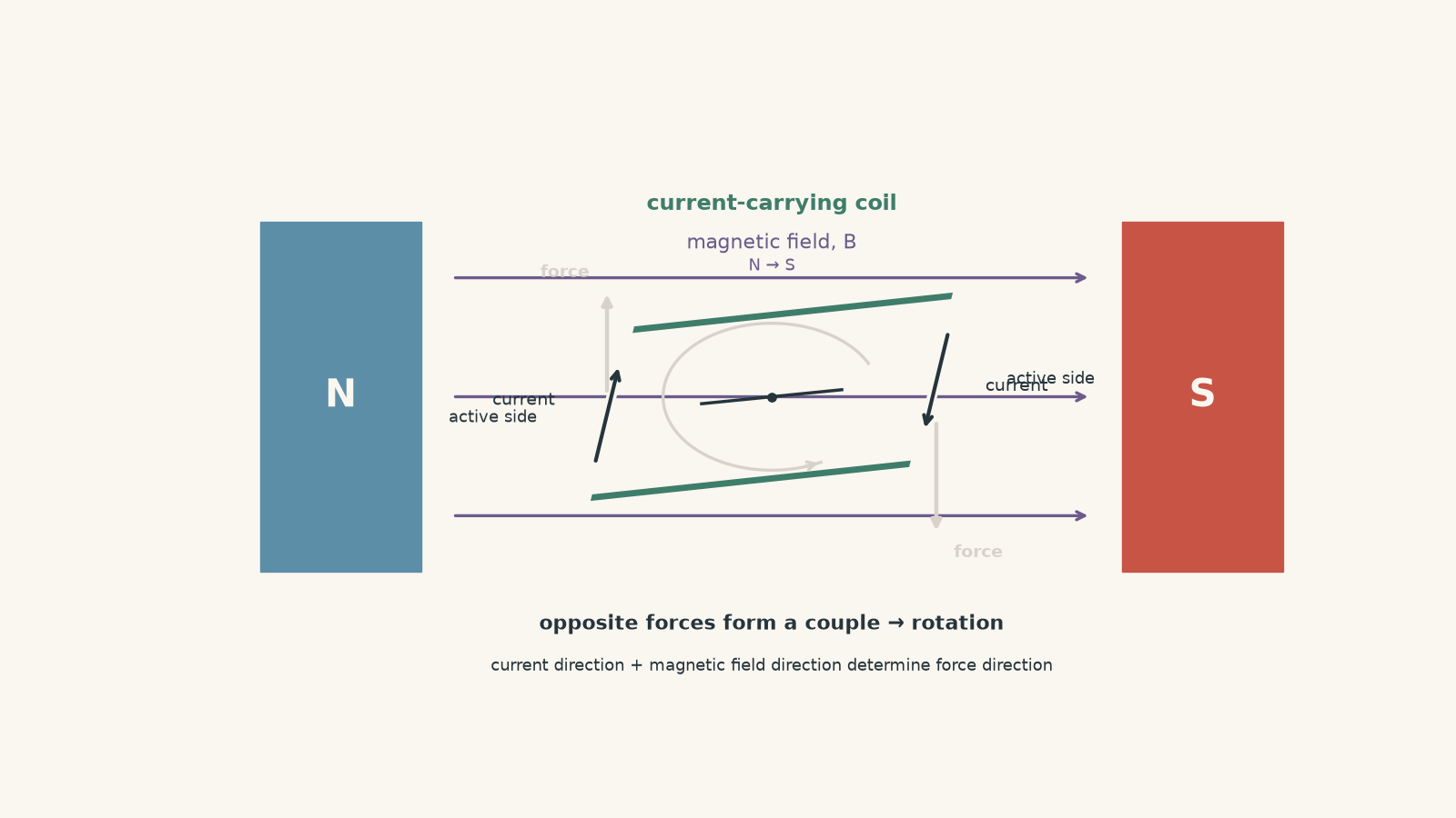
Picture a rectangular coil sitting between a north and south magnetic pole. Magnetic field lines run from north to south across the gap.
Current enters the coil through one side, travels around the loop, and leaves through the other connection. On the two opposite sides of the coil, the currents are in opposite directions.
That matters because the magnetic force also reverses when the current reverses.
So one side of the coil is forced upwards while the opposite side is forced downwards. The forces are equal and opposite, but they act at different positions.
They form a couple.
A couple produces torque, so the coil rotates.
For an ideal rectangular coil, the maximum torque can be written as
\[
\tau_{\text{max}} = nBIA
\]
where:
- \(\tau_{\text{max}}\) is maximum torque in newton metres, N m
- \(n\) is the number of turns in the coil
- \(B\) is magnetic field strength in T
- \(I\) is current in A
- \(A\) is the area of one turn in \(\text{m}^2\)
More generally,
\[
\tau = nBIA\sin\theta
\]
where \(\theta\) is the angle between the magnetic field and a line perpendicular to the plane of the coil.
That angle definition is easy to muddle. If the plane of the coil is parallel to the magnetic field, its perpendicular is at \(90^\circ\) to the field, so the torque is maximum. If the plane of the coil is perpendicular to the field, its perpendicular is parallel to the field, so the torque is zero.
Worked example: torque on a motor coil
A 25-turn rectangular coil has an area of \(3.0\times10^{-3}\text{ m}^2\). It carries a current of \(1.8\text{ A}\) in a uniform magnetic field of \(0.40\text{ T}\). The perpendicular to the coil makes an angle of \(90^\circ\) with the field. Calculate the torque on the coil.
Step 1
Since \(\theta=90^\circ\),
\[
\sin 90^\circ = 1
\]
Step 2
\[
\begin{aligned}
\tau &= nBIA\sin\theta\\
&=(25)(0.40)(1.8)(3.0\times10^{-3})(1)\\
&=5.4\times10^{-2}\text{ N m}
\end{aligned}
\]
Step 3
The magnetic field produces a torque of \(0.054\text{ N m}\) on the coil at this instant. As the coil rotates away from this orientation, the torque decreases.
So the coil converts the magnetic forces into a turning effect. But this creates another problem.
03Why the coil would not keep rotating by itself
Suppose the current direction never changed.
The coil begins rotating because one side is pushed up and the other is pushed down. After half a turn, those same pieces of wire have moved to opposite sides of the motor.
What happens if the currents in them are still flowing in their original directions?
The magnetic forces now produce torque in the opposite rotational direction.
The motor has effectively started arguing with itself.
A useful picture is two people pushing a playground merry-go-round. If they keep standing in fixed positions while the handles rotate past them, they eventually push the handles back the way they came. To keep the merry-go-round turning in one direction, they would have to change which way they push at the right moment.
The analogy breaks because people deliberately choose how to push. A motor uses electrical contacts to make the change automatically.
That is the job of the split-ring commutator.
04What the split-ring commutator does
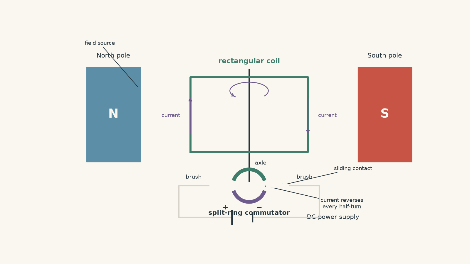
The split-ring commutator consists of two conducting half-rings attached to the rotating axle. Each end of the coil connects to one half of the ring.
The two halves are electrically insulated from each other.
As the coil rotates through each half-turn, each commutator segment moves from one brush to the other. This swaps which end of the coil is connected to the positive and negative sides of the supply.
The current through the coil therefore reverses every half-turn.
That sounds as though it should reverse the motor. It does not.
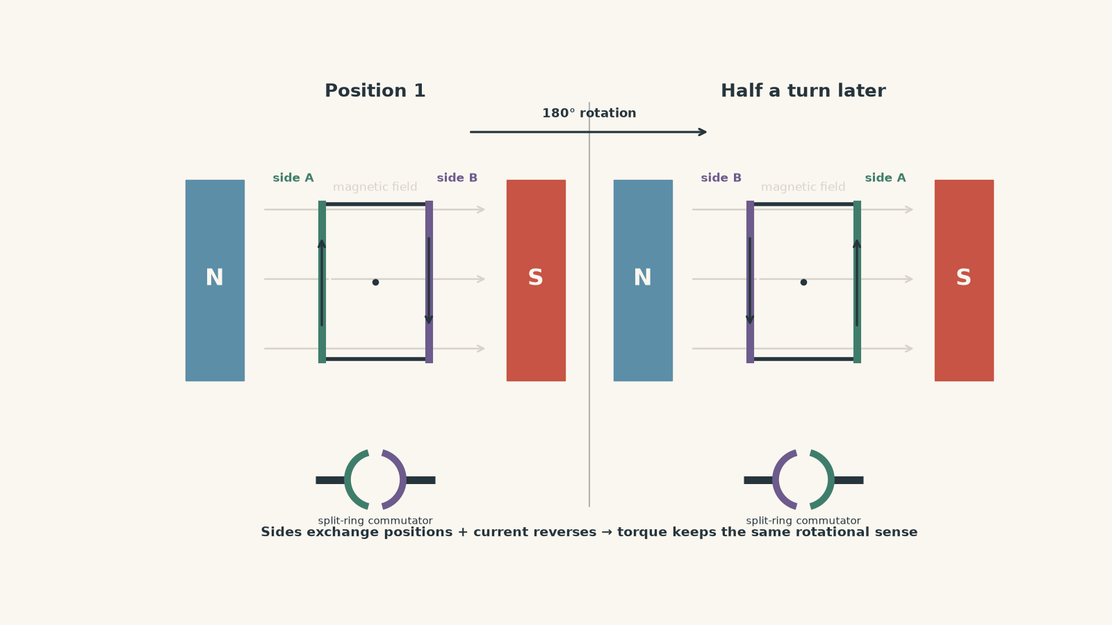
The crucial point is that the coil has also physically turned through half a revolution.
Both changes happen together:
- the two active sides of the coil exchange positions, and
- the current in the coil reverses.
Because the current reverses just as the sides swap positions, the magnetic forces continue to produce torque in the same rotational direction.
This is the central idea of the simple DC motor.
A tempting misconception
A student might reason:
If reversing current reverses magnetic force, the motor should reverse every half-turn.
That would be true if the wire stayed in the same position.
But it does not. After half a turn, each side of the coil is physically on the opposite side of the magnetic field. The commutator reverses the current to compensate for that change in position.
The force on each particular piece of wire reverses, but the torque on the rotating coil continues in the same rotational direction.
05What the brushes do
The power supply does not rotate. The coil and commutator do.
Somehow, electrical current must pass from a stationary circuit into a rotating component.
That is the job of the brushes.
The brushes are stationary conducting contacts pressed against the rotating commutator. In many real motors they are made from carbon-based materials, although the HSC idea is simply that they provide sliding electrical contact.
Their job is to:
- connect the external DC supply to the commutator,
- allow current to enter and leave the rotating coil, and
- maintain contact while the commutator spins.
The brushes do not reverse the current by themselves. They stay in place.
The geometry of the rotating split-ring commutator causes each half-ring to contact the opposite brush after every half-turn, which reverses the coil current.
That distinction is worth keeping clean:
| Component | Main role |
|---|---|
| Coil | Carries current and experiences magnetic forces that produce torque |
| Magnets | Produce the external magnetic field |
| Split-ring commutator | Reverses the current through the coil every half-turn |
| Brushes | Provide sliding electrical contact between the stationary circuit and rotating commutator |
06What the magnets do
The magnets provide the magnetic field in which the coil sits.
In a school model, these are often shown as permanent magnets labelled N and S. The field across the gap is usually treated as approximately uniform and directed from north to south.
Without an external magnetic field, the current-carrying coil would not experience the motor-effect forces described by \(F=BIL\sin\theta\).
Increasing \(B\) increases the magnetic force on the coil and therefore increases the available torque, assuming the other variables remain unchanged.
The simplified school diagram can make it look as though the north pole is somehow “pulling” one wire while the south pole “pushes” another. That is not the useful model. The magnetic field fills the region between the poles, and the force depends on the interaction between that field and the moving charges that make up the current.
07Following one complete rotation
The easiest way to understand all four components is to track the motor through a full cycle.
Position 1: the coil has large torque
The DC supply drives current through a brush, into one commutator segment, around the coil, through the other commutator segment, and back through the second brush.
The coil’s opposite sides carry currents in opposite directions.
The magnetic field produces opposite forces on those sides, creating a torque.
The coil accelerates rotationally.
Position 2: the coil approaches the zero-torque position
As the coil turns, the angle \(\theta\) in
\[
\tau=nBIA\sin\theta
\]
changes.
The torque decreases and eventually reaches zero when the perpendicular to the coil is parallel or antiparallel to the magnetic field.
The coil does not normally stop instantly at that point because it already has angular velocity and therefore rotational inertia.
Position 3: commutation occurs
Near this position, the split-ring contacts change brushes.
The connection between the supply and the two ends of the coil is reversed.
The current in the coil reverses.
Position 4: torque builds again in the same rotational direction
After passing the zero-torque position, the coil is on the other side.
Because the current has reversed, the magnetic forces now produce torque that continues the existing rotation rather than opposing it.
The sequence repeats every half-turn.
In an idealised HSC motor, we often treat the reversal as instantaneous. A real motor has more complicated contact behaviour and is designed to make this switching process work reliably.
Worked example: force and torque in a coil
A simple DC motor has a 40-turn rectangular coil. Each active side inside the magnetic field is \(5.0\text{ cm}\) long. The two active sides are \(4.0\text{ cm}\) apart. The coil carries \(2.5\text{ A}\) in a magnetic field of \(0.30\text{ T}\). At this instant, the active sides are perpendicular to the magnetic field.
Calculate:
- the magnetic force on each active side, and
- the torque on the entire 40-turn coil.
Step 1
\[
5.0\text{ cm}=0.050\text{ m}
\]
and
\[
4.0\text{ cm}=0.040\text{ m}
\]
Step 2
Since the wire is perpendicular to the field, \(\sin90^\circ=1\).
\[
\begin{aligned}
F&=BIL\sin\theta\\
&=(0.30)(2.5)(0.050)(1)\\
&=3.75\times10^{-2}\text{ N}
\end{aligned}
\]
So each active side of one turn experiences a force of \(0.0375\text{ N}\).
Step 3
The two forces form a couple. The perpendicular separation between their lines of action is \(0.040\text{ m}\).
\[
\begin{aligned}
\tau_{\text{one turn}}
&=F\times d\\
&=(0.0375)(0.040)\\
&=1.50\times10^{-3}\text{ N m}
\end{aligned}
\]
where \(d\) is the separation of the forces.
Step 4
\[
\begin{aligned}
\tau_{\text{total}}
&=40(1.50\times10^{-3})\\
&=6.0\times10^{-2}\text{ N m}
\end{aligned}
\]
The total torque is therefore
\[
\tau_{\text{total}}=0.060\text{ N m}
\]
Each turn experiences the same basic motor effect, so using more turns increases the total torque.
08What happens if one component is removed?
Thinking about failure is often more useful than memorising a definition.
Remove the magnets
There is no useful external magnetic field through the coil.
From \(F=BIL\sin\theta\), if \(B=0\), the magnetic force is zero. The motor produces no electromagnetic torque.
Break the coil
The circuit is open, so current cannot flow.
If \(I=0\), the magnetic force and torque are zero.
Remove the brushes
The stationary supply no longer has a continuous electrical connection to the rotating commutator.
Current cannot be maintained through the rotating coil.
Replace the split ring with two continuous rings
Now each end of the coil stays connected to the same supply terminal throughout the rotation.
The current no longer reverses every half-turn.
The magnetic torque therefore changes rotational direction after the coil passes the neutral position. The arrangement will not behave like the simple continuously rotating DC motor being studied here.
Continuous rings are instead associated with another machine: an AC generator. The contrast becomes especially useful when studying AC generators, sinusoidal emf, and slip rings.
09A better way to remember the four components
Avoid memorising four isolated definitions. Follow the energy and the forces.
The magnets provide the field.
The supply drives current through the brushes and commutator into the coil.
The current-carrying coil interacts with the field and experiences magnetic forces.
Those forces produce torque.
The commutator reverses the current at the right stage of each rotation so the torque continues in one rotational direction.
That is the whole motor as one causal chain:
\[
\text{electrical input}
\rightarrow
\text{current in magnetic field}
\rightarrow
\text{magnetic forces}
\rightarrow
\text{torque}
\rightarrow
\text{rotation}
\]
The brushes and commutator are not extra decorations on that chain. They are what allow the rotating electrical circuit to stay connected and keep producing useful torque.
10Questions and solutions
Question 1
A simple DC motor contains a rectangular coil between two permanent magnets.
Explain the role of:
a. the magnets
b. the coil
c. the brushes
d. the split-ring commutator
Solution 1
The magnets provide the magnetic field, the coil carries current and experiences the forces that produce torque, the brushes connect the stationary supply to the rotating commutator, and the split-ring commutator reverses the coil current every half-turn.
The magnetic force on a current-carrying wire is described by
\[
F=BIL\sin\theta
\]
so both a magnetic field and a current are required for the motor effect.
The opposite active sides of the coil carry current in opposite directions, so they experience forces in opposite directions. Because the forces act at different positions, they form a couple and produce torque.
A common mistake is to say that the commutator “makes the motor spin”. More precisely, the coil-field interaction produces the torque. The commutator reverses current at the appropriate point so that the torque continues in the same rotational direction.
Question 2
A 60-turn coil in a simple DC motor has an area of \(2.5\times10^{-3}\text{ m}^2\). It carries a current of \(1.6\text{ A}\) in a \(0.35\text{ T}\) magnetic field.
a. Calculate the maximum torque.
b. The current is doubled while all other quantities remain unchanged. Calculate the new maximum torque.
c. Explain why doubling the current does not mean that the motor must rotate at exactly twice its original steady speed.
Solution 2
The maximum torque is \(0.084\text{ N m}\), increasing to \(0.168\text{ N m}\) when the current is doubled, but this does not imply twice the steady rotational speed.
For maximum torque,
\[
\tau_{\text{max}}=nBIA
\]
For part a,
\[
\begin{aligned}
\tau_{\text{max}}
&=(60)(0.35)(1.6)(2.5\times10^{-3})\\
&=8.4\times10^{-2}\text{ N m}
\end{aligned}
\]
Therefore,
\[
\tau_{\text{max}}=0.084\text{ N m}
\]
For part b, the new current is
\[
I=3.2\text{ A}
\]
so
\[
\begin{aligned}
\tau_{\text{max}}
&=(60)(0.35)(3.2)(2.5\times10^{-3})\\
&=0.168\text{ N m}
\end{aligned}
\]
Doubling current doubles the magnetic torque at a given orientation because torque is directly proportional to \(I\).
The tempting conclusion is that twice the torque must produce twice the speed. Torque, however, is related directly to angular acceleration, not directly to angular speed. As the motor speeds up, other effects become important, including mechanical resistance and the induced voltage known as back emf. These affect the current and eventual steady operating speed.
The role of that induced voltage is developed further in tutorgum’s guide to back emf in a DC motor.
Question 3
A student says:
“The split-ring commutator cannot keep a DC motor rotating in one direction because it reverses the current every half-turn. Reversing current reverses the magnetic force, so the motor must reverse.”
Explain precisely why the conclusion is wrong.
Solution 3
The conclusion is wrong because after half a turn, the coil has changed position as well as current direction; these two reversals together keep the torque in the same rotational direction.
For a given piece of wire, reversing the current does reverse its magnetic force if the magnetic field is unchanged. The student’s statement is correct that far.
The missing step is spatial.
After half a rotation, the side of the coil that was originally on the left is now on the right, and the side that was on the right is now on the left. If the current were not reversed, the resulting forces would produce torque opposite to the original rotational direction.
The split-ring commutator reverses the current just as the coil passes through this change of orientation. The magnetic force on each physical side reverses, but that side is now in the opposite position.
The result is that the pair of forces continues to produce torque in the original rotational direction.
The tempting route is to track only current direction. For rotational problems, force direction is not enough. You must also ask where the force acts relative to the axis.
Question 4
A simple DC motor is rotating clockwise when viewed from one end of its axle. A technician accidentally fixes the split-ring commutator so that its two segments can no longer exchange brushes. The electrical supply remains connected, and the coil is initially rotating rapidly.
Assume friction is small but not zero.
Describe what happens to the coil over the next several half-turns. Do not simply state that “the motor stops”. Explain the changes in torque and motion.
Solution 4
The coil will not continue receiving torque in one rotational direction; after crossing the neutral position, the electromagnetic torque reverses, so the coil’s motion will generally slow, reverse, and tend towards oscillation about a preferred orientation before friction removes its mechanical energy.
While the current remains fixed in direction, the magnetic forces on the coil are tied to the coil’s orientation.
Suppose the coil initially has clockwise angular velocity. Before it reaches the zero-torque orientation, the electromagnetic torque may still act clockwise and increase or support that motion.
The coil then passes the orientation where
\[
\tau=nBIA\sin\theta=0
\]
Because it already has angular velocity, it can coast through this point.
Once it moves beyond that orientation, the same fixed current now produces torque in the opposite, anticlockwise direction. That torque reduces the clockwise angular velocity.
If the coil has enough rotational kinetic energy, it overshoots the next zero-speed position before reversing. It then rotates anticlockwise, but the magnetic torque changes with angle and can again act to restore it towards the stable orientation.
The coil therefore behaves more like a rotational oscillator than a functioning motor. With friction and electrical losses, the oscillations die away.
The tempting answer is “no commutator means no torque”. That is not correct. Current still flows, so magnetic torque can still exist. What is lost is the automatic reversal that keeps the torque driving one continuous rotational direction.
Question 5
Consider an ideal simple DC motor with negligible friction. Its rectangular coil is initially stationary exactly at an orientation where its magnetic torque is zero. A DC supply is connected correctly through brushes and a split-ring commutator.
A student argues:
“The commutator guarantees continuous rotation, so the motor must start turning.”
Another student argues:
“The torque is zero initially, so it can never start.”
Using only the simple motor model, decide what can actually be concluded. Then explain how the answer changes if the coil is displaced by a tiny angle before the supply is connected.
Solution 5
If the ideal coil begins exactly at a zero-torque orientation with exactly zero angular velocity, the simple model does not predict that it will spontaneously start rotating; with a tiny angular displacement, however, a non-zero torque acts and the coil can begin rotating.
The governing equation is
\[
\tau=nBIA\sin\theta
\]
At a zero-torque orientation, \(\theta=0^\circ\) or \(180^\circ\), so
\[
\sin\theta=0
\]
and therefore
\[
\tau=0
\]
With zero torque, the coil has zero angular acceleration at that exact instant. If it is also perfectly stationary and nothing disturbs it, the ideal model contains no mechanism that selects a direction and starts the rotation.
This shows the limitation of saying that the commutator “makes the motor rotate”. The commutator does not create torque when the coil-field geometry gives zero torque. It switches the electrical connection as an already rotating coil passes through appropriate positions.
Now displace the coil by a tiny angle. Then \(\sin\theta\neq0\), so a small magnetic torque appears.
That torque produces angular acceleration. Once the coil begins moving, it can gain angular velocity before reaching the next zero-torque position. Its inertia can carry it through that position, and the commutator can then reverse the current so that torque builds again in the same rotational direction.
The subtle point is that the zero-torque position and a guaranteed stopping point are not the same thing. A moving coil can pass through zero torque because it has angular momentum. A perfectly stationary ideal coil placed exactly there has no such motion to carry it through.
Real motors avoid relying on such a fragile single-coil arrangement. Multiple coils and commutator segments can be arranged so that useful torque is available over more of the rotation. That takes the simple four-component picture and leads naturally into the design of practical motors, while the next major physics step is understanding why a spinning motor also behaves partly like a generator and develops back emf.