
DC generators: how rotating coils produce direct current
Learn how rotating coils induce emf and how a split-ring commutator converts the changing coil output into pulsating direct current.
Spin a rectangular coil between the poles of a magnet and you can produce an emf. But there is an immediate problem: after half a turn, each side of the coil moves through the magnetic field in the opposite direction. So why doesn’t a DC generator simply produce alternating current?
Predict it before reading on. If the induced emf in the rotating coil reverses every half-turn, what could keep the current through an external resistor travelling in the same direction?
The answer is not a special kind of electromagnetic induction. The emf in the coil really does reverse. A DC generator uses a split-ring commutator to swap the coil’s connections to the external circuit at exactly the same time. Two reversals happen together, leaving the external current pointing the same way.
That is the central idea of a DC generator.
01Start with one moving conductor
Imagine a straight metal wire moving sideways through a magnetic field. The wire contains mobile electrons, and those charges are moving with the wire.
A moving charge in a magnetic field experiences a magnetic force:
\[
F = qvB\sin\theta
\]
where \(F\) is the magnetic force in newtons, \(q\) is the charge in coulombs, \(v\) is the charge’s velocity in metres per second, \(B\) is the magnetic field strength in tesla, and \(\theta\) is the angle between the velocity and the magnetic field.
When the wire moves perpendicular to the field, \(\theta = 90^\circ\), so the magnetic force is largest. Positive and negative charges are pushed towards opposite ends of the conductor. That separation of charge creates a potential difference, or emf, across the wire.
This gives us a useful first picture: move a conductor through a magnetic field, and charges inside it can be pushed along the conductor.
It is not yet the complete explanation of a generator. A practical generator uses a whole rotating coil, so different parts of the conductor move in different directions and the magnetic flux through the coil changes continuously.
02Put the conductor into a rotating coil
Take a rectangular coil and place it between a north and south magnetic pole. Suppose an external force turns the coil at a steady angular speed.
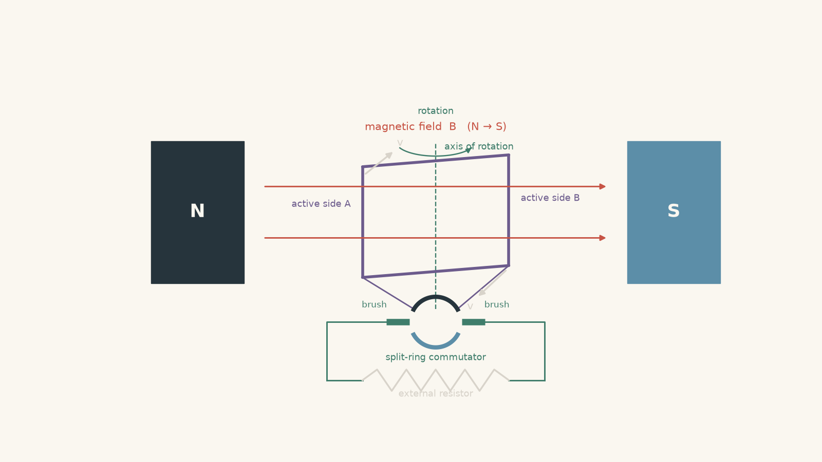
Focus first on the two sides of the coil that cut across the magnetic field.
As the coil turns:
- one side moves upwards while the other moves downwards,
- magnetic forces push charges in opposite directions on those two sides,
- the effects add around the loop, producing an emf.
Now follow the coil for half a revolution. Each side is physically on the opposite part of its path and has reversed its velocity through the field.
What should happen to the induced emf?
It reverses.
If we connected the spinning coil directly to two continuous slip rings, the external current would therefore reverse every half-turn. That arrangement produces alternating current.
A DC generator needs one more component.
03The split-ring commutator changes what the external circuit sees
A split-ring commutator consists of two conducting half-rings attached to opposite ends of the rotating coil. Stationary carbon brushes press against the rotating segments and connect them to the external circuit.
During one half-turn, one end of the coil touches brush A and the other touches brush B.
After half a turn, the commutator segments have swapped brushes.
That swap occurs just as the polarity of the induced emf in the coil reverses.
So we get two reversals:
- the induced emf around the rotating coil reverses;
- the commutator reverses which end of the coil is connected to each brush.
The reversals cancel as far as the external circuit is concerned. The current through the load continues in the same direction.
A slightly silly analogy helps here. Imagine two people taking turns carrying a tray through a doorway, but every time they swap sides, they also swap which hand passes the tray forward. Lots of reversing is happening internally, yet the tray still moves through the doorway in one overall direction.
The analogy breaks because a commutator is not physically handing current from one carrier to another. It is switching electrical connections. But it captures the important point: the internal direction can reverse while the external direction stays unchanged.
04A DC generator does not produce perfectly constant DC
This is one of the most tempting mistakes in this topic.
A student sees the words “DC generator” and pictures a horizontal voltage line like a battery.
An elementary DC generator does not produce that.
The rotating coil produces a sinusoidally varying emf. The split-ring commutator flips the negative halves of that waveform so that the external polarity stays the same.
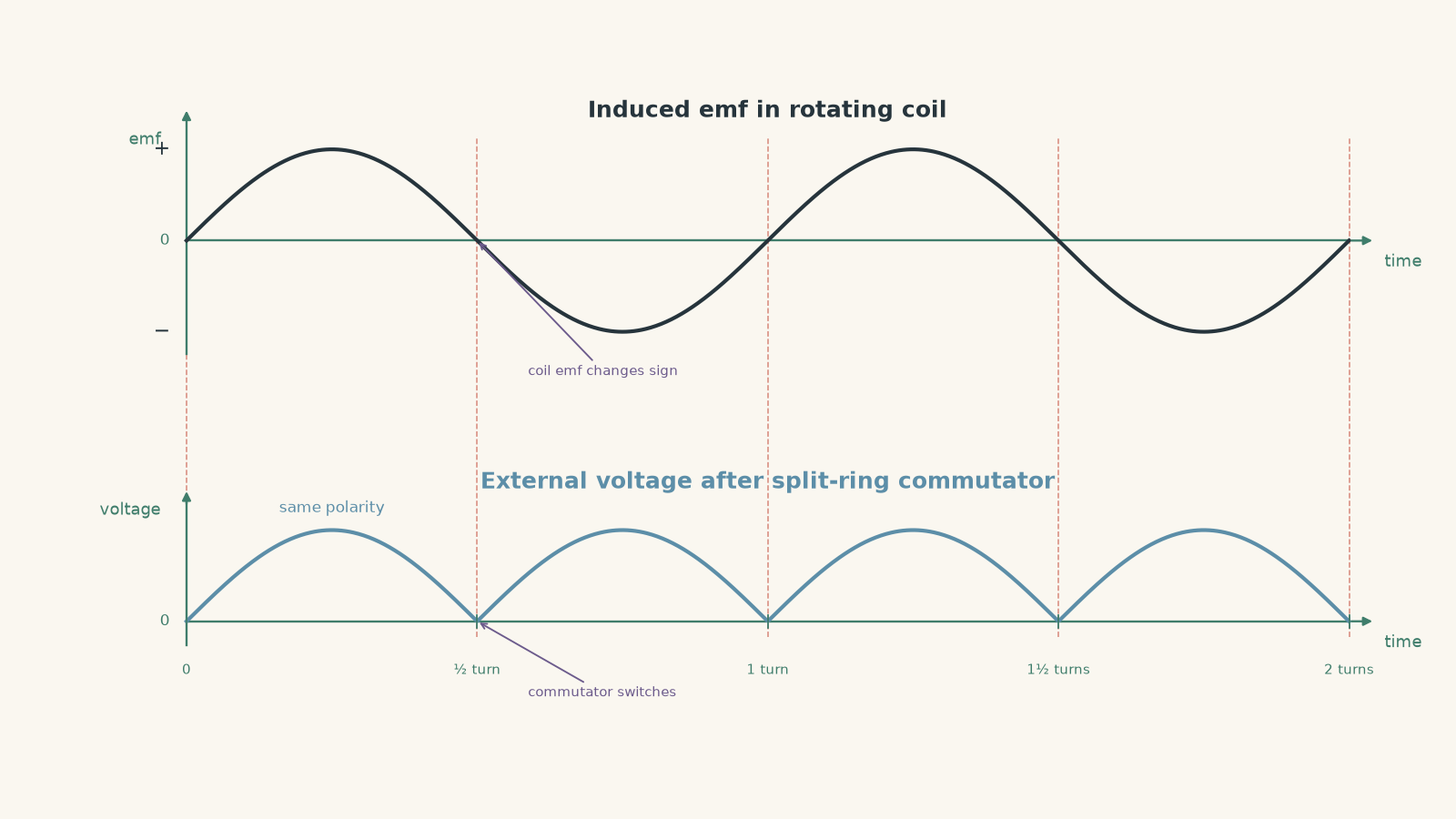
The result is pulsating DC. It has one direction, but its magnitude changes continuously.
Real DC generators can use many coils and many commutator segments. Their emf peaks occur at different times, so the total output is much smoother.
05Why the emf changes during each rotation
We can now make the model more precise using magnetic flux.
For a uniform magnetic field passing through a flat coil,
\[
\Phi = BA\cos\theta
\]
where \(\Phi\) is the magnetic flux through one turn in webers, \(B\) is magnetic field strength in tesla, \(A\) is the area of the loop in square metres, and \(\theta\) is the angle between the magnetic field and the normal to the plane of the coil.
The normal is an imaginary line perpendicular to the face of the coil.
That angle definition matters. If the plane of the coil is perpendicular to the magnetic field, its normal is parallel to the field, so \(\theta = 0^\circ\) and the flux is maximum.
If the plane of the coil is parallel to the magnetic field, the normal is at \(90^\circ\) to the field, so the flux is zero.
Faraday’s law tells us that an emf is induced when the magnetic flux linkage changes:
\[
\varepsilon = -N\frac{\Delta\Phi}{\Delta t}
\]
where \(\varepsilon\) is the induced emf in volts and \(N\) is the number of turns.
The minus sign represents Lenz’s law: the induced effect acts in a direction that opposes the change that produced it.
Here is the subtle part. The emf is not greatest when the flux is greatest. It is greatest when the flux is changing fastest.
Suppose the coil is momentarily perpendicular to the field. The flux is at a maximum, but for that instant its rate of change is zero. The induced emf is therefore zero.
A quarter-turn later, the flux is zero, but it is changing most rapidly. The magnitude of the emf is then maximum.
That distinction appears constantly in generator questions.
06The emf equation for a rotating coil
If the coil rotates at constant angular speed \(\omega\), its angle can be written as
\[
\theta = \omega t
\]
where \(\omega\) is angular speed in radians per second and \(t\) is time in seconds.
Substituting this into the flux expression gives
\[
\Phi = BA\cos(\omega t)
\]
For \(N\) turns, differentiating the flux linkage gives
\[
\varepsilon = NBA\omega\sin(\omega t)
\]
if we choose \(t=0\) when the flux is maximum.
The peak induced emf is therefore
\[
\varepsilon_{\text{max}} = NBA\omega
\]
This equation gives a useful decision rule:
| Change | Effect on peak emf |
|---|---|
| Double \(N\) | doubles \(\varepsilon_{\text{max}}\) |
| Double \(B\) | doubles \(\varepsilon_{\text{max}}\) |
| Double \(A\) | doubles \(\varepsilon_{\text{max}}\) |
| Double \(\omega\) | doubles \(\varepsilon_{\text{max}}\) |
Notice what the commutator does not appear in this equation. The commutator does not make the electromagnetic induction stronger. It changes the connections so that the external polarity remains the same.
For an ideal single-coil DC generator, the external emf can be represented as
\[
\varepsilon_{\text{out}} = \left|\varepsilon_{\text{max}}\sin(\omega t)\right|
\]
The absolute-value signs are the mathematical version of the split-ring action.
Worked example: Find the maximum emf
A 120-turn rectangular coil has an area of \(3.0\times10^{-3}\text{ m}^2\). It rotates at \(25\text{ rad s}^{-1}\) in a uniform magnetic field of \(0.40\text{ T}\). Calculate the maximum induced emf.
Step 1
We have
\[
N=120,\qquad
B=0.40\text{ T},\qquad
A=3.0\times10^{-3}\text{ m}^2,\qquad
\omega=25\text{ rad s}^{-1}.
\]
Step 2
\[
\varepsilon_{\text{max}}=NBA\omega
\]
Step 3
\[
\varepsilon_{\text{max}}
=(120)(0.40)(3.0\times10^{-3})(25)
=3.6\text{ V}
\]
The maximum induced emf is
\[
\boxed{\varepsilon_{\text{max}}=3.6\text{ V}}
\]
This means the external voltage of an ideal single-coil DC generator rises from zero to \(3.6\text{ V}\), falls back to zero, and then repeats with the same polarity.
07Where in the rotation is the emf largest?
Try to predict this from the physical motion before using the equation.
When the plane of the coil is perpendicular to the magnetic field, each active side is momentarily moving roughly parallel to the field. It is not cutting across field lines effectively. The emf is zero.
After a quarter-turn, the plane of the coil is parallel to the field. The active sides move perpendicular to the field, so they cut through the field most rapidly. The emf magnitude is maximum.
Another quarter-turn later, the emf returns to zero.
So during one complete rotation of the coil, the magnitude follows this pattern:
\[
0\rightarrow \varepsilon_{\text{max}}\rightarrow0
\rightarrow\varepsilon_{\text{max}}\rightarrow0
\]
The two maxima have opposite polarity inside the rotating coil. After commutation, both appear with the same polarity at the external brushes.
Worked example: Find the output at a particular angle
A 200-turn coil of area \(4.0\times10^{-3}\text{ m}^2\) rotates in a \(0.30\text{ T}\) magnetic field at \(50\text{ rad s}^{-1}\). At one instant, the normal to the coil makes an angle of \(30^\circ\) with the magnetic field.
Calculate the magnitude of the external emf from an ideal split-ring DC generator at this instant.
Step 1
\[
\varepsilon_{\text{max}}=NBA\omega
\]
Substituting,
\[
\varepsilon_{\text{max}}
=(200)(0.30)(4.0\times10^{-3})(50)
=12\text{ V}
\]
Step 2
Because \(\theta\) is measured between the field and the coil’s normal,
\[
|\varepsilon|
=\varepsilon_{\text{max}}|\sin\theta|
\]
so
\[
|\varepsilon|
=(12)|\sin30^\circ|
=(12)(0.5)
=6.0\text{ V}.
\]
Step 3
The external emf is
\[
\boxed{6.0\text{ V}}
\]
at that instant. The split-ring commutator determines the external polarity, so on the chosen output terminal this \(6.0\text{ V}\) belongs to the same polarity as the corresponding pulse during the next half-turn.
The common trap is using \(12\cos30^\circ\). Cosine describes the flux here, not the induced emf. Emf depends on the rate of change of flux.
08Current requires a complete circuit
An emf can exist even if no load is connected. Current requires a closed conducting path.
If we model the generator as having internal resistance \(r\) and connect it to an external load resistance \(R\), then at any instant
\[
I=\frac{\varepsilon_{\text{out}}}{R+r}
\]
where \(I\) is the current in amperes.
For a simple resistive load, the current therefore has the same pulsating shape as the output emf.
Increasing the rotation speed does more than make the pulses arrive more often. Since
\[
\varepsilon_{\text{max}}=NBA\omega,
\]
a larger angular speed also increases their height.
Double \(\omega\), and the peak emf doubles.
09Why generating electrical energy makes the generator harder to turn
Suppose the generator is connected to a resistor. Current now flows through the rotating coil.
A current-carrying conductor in a magnetic field experiences a magnetic force. The resulting torque acts against the rotation that is producing the current.
That is Lenz’s law showing up mechanically.
This gives an important energy check. If connecting a load caused the generator to speed itself up, the machine would be producing both electrical energy and extra rotational energy with no additional input. That cannot happen.
Instead, when more electrical power is drawn, the external device driving the generator must supply more mechanical energy.
This also explains a result that can initially feel odd: although the current in the rotating coil reverses every half-turn, the electromagnetic torque does not suddenly start helping the rotation. The commutator and the induced-current reversal work together so that the generator’s electromagnetic effect continues to oppose the driving motion.
The same underlying induction idea appears from the other direction in a motor. When a DC motor is already spinning, its rotating conductors generate a voltage that opposes the supply. That is back emf in a DC motor.
10The three ideas to keep separate
Most DC-generator mistakes come from blending together three different things.
| Quantity | What happens every half-turn? |
|---|---|
| Induced emf in the rotating coil | reverses polarity |
| Coil current when supplying a load | reverses direction within the rotating coil |
| External current through the load | remains in the same overall direction because the commutator swaps the connections |
So saying “the current never reverses” is too vague.
The external current does not reverse. The current direction relative to the rotating coil does.
Likewise, saying “the split ring produces the emf” is incorrect. Electromagnetic induction produces the emf. The split ring mechanically switches the external connections.
11Questions and solutions
Question 1
A 150-turn coil with area \(2.5\times10^{-3}\text{ m}^2\) rotates at \(40\text{ rad s}^{-1}\) in a uniform magnetic field of \(0.20\text{ T}\).
Calculate the maximum emf produced by the coil.
Solution 1
The maximum induced emf is \(\boxed{3.0\text{ V}}\).
For a rotating coil,
\[
\varepsilon_{\text{max}}=NBA\omega.
\]
Here,
\[
N=150,\qquad
B=0.20\text{ T},\qquad
A=2.5\times10^{-3}\text{ m}^2,\qquad
\omega=40\text{ rad s}^{-1}.
\]
Therefore,
\[
\varepsilon_{\text{max}}
=(150)(0.20)(2.5\times10^{-3})(40)
=3.0\text{ V}.
\]
The coil’s induced emf varies between \(+3.0\text{ V}\) and \(-3.0\text{ V}\). With an ideal split-ring commutator, the external circuit instead receives pulses between \(0\) and \(3.0\text{ V}\) with one polarity.
A tempting mistake is to assume that a DC generator supplies \(3.0\text{ V}\) continuously. The calculated value is the maximum, not a constant output.
Question 2
A DC generator has a peak induced emf of \(18\text{ V}\). At one instant, the normal to its rotating coil makes an angle of \(140^\circ\) with the magnetic field.
The generator is connected to a \(5.0\,\Omega\) resistor and has an internal resistance of \(1.0\,\Omega\).
Calculate:
a. the magnitude of the induced emf at this instant, and
b. the magnitude of the load current.
Explain why the current through the external resistor can still have the same direction as it did when the coil was at \(40^\circ\).
Solution 2
The emf magnitude is approximately \(\boxed{11.6\text{ V}}\), and the current magnitude is approximately \(\boxed{1.93\text{ A}}\). The external current retains its direction because the split-ring commutator has swapped the coil’s connections during the half-turn.
For the rotating coil,
\[
|\varepsilon|
=\varepsilon_{\text{max}}|\sin\theta|.
\]
Substituting,
\[
|\varepsilon|
=(18)|\sin140^\circ|
\approx(18)(0.643)
\approx11.6\text{ V}.
\]
The total circuit resistance is
\[
R_{\text{total}}=5.0+1.0=6.0\,\Omega.
\]
Using Ohm’s law,
\[
I=\frac{\varepsilon}{R_{\text{total}}}
=\frac{11.6}{6.0}
\approx1.93\text{ A}.
\]
The tempting argument is that \(140^\circ\) lies in a different half-turn from \(40^\circ\), so the external current must have reversed. The first part is true for the emf inside the rotating coil: its polarity has reversed.
However, the commutator also swaps which coil end contacts each brush. The two reversals occur together, so the external resistor sees the same polarity.
Question 3
A single-coil DC generator rotates at constant angular speed. Its maximum emf is \(24\text{ V}\), and its total circuit resistance is \(8.0\,\Omega\).
At an instant when the angle between the coil’s normal and the magnetic field is \(30^\circ\):
a. calculate the current magnitude,
b. calculate the electrical power being delivered to the circuit, and
c. compare the opposing electromagnetic torque at this instant with its value when the angle is \(90^\circ\). Assume the rotation speed and resistance remain constant.
Solution 3
The current is \(\boxed{1.5\text{ A}}\), the electrical power is \(\boxed{18\text{ W}}\), and the opposing electromagnetic torque is \(\boxed{\tfrac14}\) of its maximum value at \(90^\circ\).
First find the instantaneous emf:
\[
|\varepsilon|
=\varepsilon_{\text{max}}|\sin30^\circ|
=(24)(0.5)
=12\text{ V}.
\]
The current is therefore
\[
I=\frac{\varepsilon}{R}
=\frac{12}{8.0}
=1.5\text{ A}.
\]
The electrical power is
\[
P=\varepsilon I
=(12)(1.5)
=18\text{ W}.
\]
Now compare this with the \(90^\circ\) position.
At \(90^\circ\),
\[
\varepsilon=24\text{ V},
\]
so
\[
I=\frac{24}{8.0}=3.0\text{ A}
\]
and
\[
P=(24)(3.0)=72\text{ W}.
\]
At constant angular speed, mechanical power associated with the opposing electromagnetic torque satisfies
\[
P=\tau\omega,
\]
where \(\tau\) is torque in newton metres and \(\omega\) is angular speed. Since \(\omega\) is unchanged,
\[
\frac{\tau_{30}}{\tau_{90}}
=
\frac{P_{30}}{P_{90}}
=
\frac{18}{72}
=
\frac14.
\]
So the opposing torque at \(30^\circ\) is one quarter of its value at \(90^\circ\).
A plausible wrong route is to argue that the torque should be half as large because the emf is half as large. But the current is also halved. For a fixed resistance, electrical power varies as
\[
P=\frac{\varepsilon^2}{R},
\]
so halving the emf reduces the power, and therefore the required opposing torque at fixed speed, to one quarter.
Question 4
An ideal DC generator has a single rotating coil and a split-ring commutator. Normally, the brushes change from one commutator segment to the other at the instant when the induced emf passes through zero.
Suppose the brushes are incorrectly positioned so that the connection switches \(20^\circ\) of rotation after each zero crossing of the coil’s induced emf.
Explain what happens to the polarity of the external voltage during each revolution. Does the generator still produce current in only one direction at all times?
Assume perfect instantaneous switching and ignore sparking.
Solution 4
No. The external voltage has the intended polarity for most of each revolution, but it has the opposite polarity for a \(20^\circ\) interval after each emf zero crossing. There are two such intervals per revolution.
The key is that two events are supposed to occur together:
- the induced emf in the coil reverses sign;
- the commutator swaps the coil’s connection to the brushes.
With correct timing, these two reversals cancel from the external circuit’s point of view.
Here they do not happen together.
Immediately after a zero crossing, the coil emf has already reversed because the coil has entered the next half of its rotation. But for another \(20^\circ\), the old commutator connection is still being used.
During that interval, there has been only one reversal rather than two. The external polarity therefore reverses.
Once the delayed commutator switch finally occurs, the second reversal happens and the intended external polarity is restored.
The same problem occurs at the next zero crossing, so there are two wrong-polarity intervals in every \(360^\circ\) revolution.
Their total angular extent is
\[
2(20^\circ)=40^\circ.
\]
Thus the output has the wrong polarity for the fraction
\[
\frac{40^\circ}{360^\circ}
=\frac19
\]
of each revolution.
A tempting argument is that the commutator will “fix the direction eventually”, so the output still counts as unidirectional DC. The timing is the constraint that breaks that argument. A split-ring commutator works only because it switches as the coil emf changes sign. Delaying the switch allows a short reverse-voltage pulse into the external circuit.
This also explains why real commutation is an engineering problem rather than merely having two bits of metal shaped like semicircles.
Question 5
A designer wants to make the output of a DC generator smoother.
Instead of one coil, the generator contains two identical coils mounted \(90^\circ\) apart around the same axis. Each coil has its own ideal commutator. Their rectified output voltages are connected in series so that they add.
Each coil would have a maximum emf \(E_0\) if used alone.
Let \(\theta\) be the angle for which the first coil has output
\[
E_1=E_0|\sin\theta|.
\]
Because the second coil is \(90^\circ\) ahead, its output is
\[
E_2=E_0|\cos\theta|.
\]
a. Find the total output at \(\theta=0^\circ\), \(45^\circ\), and \(90^\circ\).
b. A student claims: “The coils are \(90^\circ\) apart, so when one loses voltage the other gains exactly the same amount. Their total must be constant.” Determine whether this is correct.
c. Find the minimum and maximum total voltage during a quarter-turn, \(0^\circ\leq\theta\leq90^\circ\), and explain what this shows about using multiple coils in a real DC generator.
Solution 5
The total output is \(\boxed{E_0}\) at \(0^\circ\), \(\boxed{\sqrt2E_0}\) at \(45^\circ\), and \(\boxed{E_0}\) at \(90^\circ\). It is therefore smoother than the output from one coil but not constant.
The total voltage is
\[
E_{\text{total}}
=
E_1+E_2.
\]
During the first quadrant, both sine and cosine are positive, so
\[
E_{\text{total}}
=
E_0(\sin\theta+\cos\theta).
\]
At \(\theta=0^\circ\),
\[
E_{\text{total}}
=
E_0(\sin0^\circ+\cos0^\circ)
=
E_0(0+1)
=
E_0.
\]
At \(\theta=45^\circ\),
\[
E_{\text{total}}
=
E_0\left(\frac{\sqrt2}{2}+\frac{\sqrt2}{2}\right)
=
\sqrt2E_0.
\]
At \(\theta=90^\circ\),
\[
E_{\text{total}}
=
E_0(\sin90^\circ+\cos90^\circ)
=
E_0(1+0)
=
E_0.
\]
So the student’s claim cannot be correct. The total changes from \(E_0\) to \(\sqrt2E_0\) and back to \(E_0\).
The tempting reasoning comes from a genuine identity:
\[
\sin^2\theta+\cos^2\theta=1.
\]
But the generator is adding voltages, not squared voltages. Its total is proportional to
\[
\sin\theta+\cos\theta,
\]
which is not constant.
To find the extrema without heavy calculus, rewrite the sum as
\[
\sin\theta+\cos\theta
=
\sqrt2\sin(\theta+45^\circ).
\]
Over
\[
0^\circ\leq\theta\leq90^\circ,
\]
the maximum occurs at
\[
\theta=45^\circ,
\]
giving
\[
E_{\text{max,total}}=\sqrt2E_0.
\]
At either end of the interval,
\[
E_{\text{min,total}}=E_0.
\]
So
\[
\boxed{E_0\leq E_{\text{total}}\leq\sqrt2E_0}.
\]
The important conclusion is not merely that “more coils give more voltage”. Their different rotational positions make their emf peaks occur at different times. One coil can therefore provide substantial output while another is near a low point.
With more coils distributed around the rotor and more commutator segments, these overlapping contributions can make the external DC much smoother. But a finite set of ordinary rotating coils does not magically turn the induction process into a perfectly constant emf. The smoothing comes from combining staggered pulsating outputs.
That idea is the next useful step: once you understand that the commutator controls polarity while the coil geometry controls the changing magnitude, the design of practical generators becomes much easier to reason about.