
Magnetic Braking: Eddy Currents, Lenz’s Law and Energy
Learn how eddy-current braking works using Lenz's law, magnetic forces, and conservation of energy, with worked HSC Physics examples.
Drop a strong magnet through a plastic tube and it falls normally. Drop the same magnet through a copper tube and it can drift down strangely slowly, even though copper is not ferromagnetic.
So what is pushing back on the magnet?
Before reading on, make a prediction. Is the copper simply becoming attracted to the magnet, or is something happening only because the magnet is moving?
The second idea is the important one. Motion changes the magnetic flux through parts of the conductor. That changing flux produces circulating currents in the metal. Those currents create their own magnetic fields, and the resulting interaction opposes the change that produced them.
Those circulating currents are called eddy currents. Put them in the right geometry, and you have a magnetic brake.
01Why a moving conductor can experience magnetic drag
Imagine an aluminium plate moving to the right through the narrow gap between two strong permanent magnets.
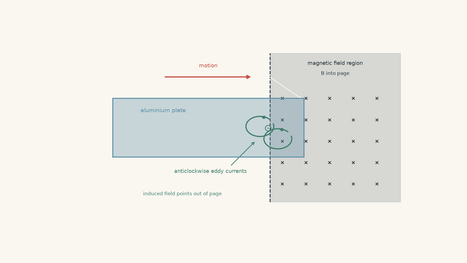
The plate is a conductor, so electrons can move through it. As different parts of the plate enter the magnetic field, the magnetic flux through possible current loops inside the metal changes.
That matters because of Faraday’s law:
\[ \varepsilon=-\frac{\Delta\Phi_B}{\Delta t} \]
where:
- \(\varepsilon\) is the induced emf in volts, \(\text{V}\),
- \(\Phi_B\) is magnetic flux in webers, \(\text{Wb}\), and
- \(t\) is time in seconds, \(\text{s}\).
For a uniform magnetic field perpendicular to an area,
\[ \Phi_B=BA \]
where \(B\) is magnetic field strength in tesla, \(\text{T}\), and \(A\) is the area in square metres, \(\text{m}^2\).
The minus sign in Faraday’s law is Lenz’s law. It tells us the direction of the induced effect.
The induced current creates a magnetic field that opposes the change in magnetic flux.
That wording is worth getting exactly right.
Lenz’s law does not say, “the induced current opposes the magnetic field”. It also does not fundamentally say, “the induced current opposes motion”. It opposes the change in flux.
In a magnetic brake, opposing the flux change happens to produce a force opposing the motion.
02Build the picture before using the rule
Suppose the plate moves right into a region where the external magnetic field points into the page.
Focus on a tiny possible current loop near the leading edge of the plate.
As that loop enters the field, the magnetic flux into the page increases.
What direction should the induced magnetic field point?
If you predicted out of the page, good. That induced field opposes the increase in into-the-page flux.
Using the right-hand grip rule, an out-of-page magnetic field requires an anticlockwise induced current.
Now imagine a loop at the other edge, leaving the magnetic field. Its into-page flux is decreasing. This time, the induced current produces an into-page field, trying to oppose that decrease.
So the current direction reverses between entering and leaving.
Yet the braking force still opposes the motion in both cases.
That can feel contradictory at first. It isn’t. The current reverses, but the part of the current loop sitting in the external magnetic field also changes. The resulting magnetic force still points against the plate’s motion.
This is why memorising “clockwise means braking” is useless. The direction depends on the geometry.
A useful mental model for eddy currents
A solid metal plate does not contain one tidy wire loop drawn by a textbook artist. Currents can take many closed paths through the bulk metal.
You can picture the plate as containing a huge number of possible overlapping loops. Wherever changing flux induces an emf, currents circulate through those available paths.
A slightly silly analogy is a shopping centre with no marked walking lanes. If something suddenly changes near one entrance, people can circulate around many different paths rather than following one prescribed circuit. Cutting slots through the floor would destroy some of those possible loops.
The analogy breaks because electrons are not choosing routes, and real eddy-current patterns are determined by electromagnetic fields, conductivity, and geometry. But the “many available loops” idea is useful.
03Why Lenz’s law has to oppose the change
Suppose the opposite happened.
Imagine the plate enters a magnetic field, its flux increases, and the induced current creates a field that makes that increase even larger. The stronger flux would then induce an effect that strengthened it again.
The plate could gain kinetic energy while also producing electrical energy and heat, with no external energy source.
That would violate conservation of energy.
Lenz’s law is therefore not an arbitrary direction rule. Its direction is exactly what prevents electromagnetic induction from creating energy from nowhere.
In an eddy-current brake, the energy chain is approximately:
\[ \text{mechanical energy}\rightarrow\text{electrical energy in induced currents}\rightarrow\text{thermal energy} \]
The metal warms because it has electrical resistance.
For an induced current \(I\) flowing through an effective resistance \(R\), the rate of thermal energy production is
\[ P=I^2R \]
where \(P\) is power in watts, \(\text{W}\), \(I\) is current in amperes, \(\text{A}\), and \(R\) is resistance in ohms, \(\Omega\).
The permanent magnet is not a fuel tank being “used up”. The energy being dissipated comes from the moving system, or from whatever external agent is keeping that system moving.
04A simple model of magnetic braking force
Real eddy currents in a metal sheet can have complicated shapes. To understand the main relationships, it helps to replace the sheet temporarily with a simple conducting loop.
Suppose a vertical section of wire of length \(\ell\) moves sideways at speed \(v\) through a magnetic field \(B\), with the motion, wire, and field mutually perpendicular.
The motional emf is
\[ \varepsilon=B\ell v \]
If the complete loop has resistance \(R\),
\[ I=\frac{\varepsilon}{R} =\frac{B\ell v}{R} \]
The current-carrying section in the field experiences a magnetic force of magnitude
\[ F=BI\ell \]
so
\[ F =B\left(\frac{B\ell v}{R}\right)\ell =\frac{B^2\ell^2v}{R} \]
In this simple model, the braking force is proportional to speed.
That immediately predicts something useful: as the object slows down, the magnetic braking force becomes weaker.
At zero speed, there is no changing flux in this model, so there is no eddy-current braking force.
Real brakes can depart from this simple proportional relationship, especially at high speeds or with complicated conductor shapes. But the model captures the HSC idea: faster flux change generally produces a larger induced emf, larger eddy currents, and stronger magnetic drag.
Worked example: Find the induced current in a braking plate
A region of an aluminium plate can be modelled as a conducting loop of area \(0.020\text{ m}^2\) and resistance \(0.040\,\Omega\). As the plate enters a magnetic brake, the perpendicular magnetic field through this effective loop increases uniformly from \(0\) to \(0.50\text{ T}\) in \(0.10\text{ s}\).
Calculate the average induced emf and current. The external field points into the page.
Step 1
The field is perpendicular to the loop, so
\[ \Delta\Phi_B=A\Delta B =(0.020)(0.50) =0.010\text{ Wb} \]
Step 2
\[ |\varepsilon| =\frac{|\Delta\Phi_B|}{\Delta t} =\frac{0.010}{0.10} =0.10\text{ V} \]
Step 3
\[ I=\frac{\varepsilon}{R} =\frac{0.10}{0.040} =2.5\text{ A} \]
Step 4
The external flux into the page is increasing. The induced current must therefore create a field out of the page.
By the right-hand grip rule, the current is anticlockwise.
So the effective loop has an average induced emf of \(0.10\text{ V}\) and an induced current of \(2.5\text{ A}\), anticlockwise.
The important physical result is not just the current direction. That current exists because the plate is entering the field. Its interaction with the external field produces the drag that removes mechanical energy from the plate.
05Where the lost kinetic energy goes
Magnetic braking can look mysterious because nothing needs to touch the moving object.
But “no contact” does not mean “no energy transfer”.
Suppose the magnetic force on a moving plate is \(40\text{ N}\) opposite its motion while the plate travels at \(6.0\text{ m s}^{-1}\).
The rate at which the braking force removes mechanical energy is
\[ P=Fv \]
so
\[ P=(40)(6.0)=240\text{ W} \]
The plate is losing mechanical energy at \(240\text{ J s}^{-1}\).
If the idealised brake has no other significant energy transfers, that same \(240\text{ W}\) appears as thermal energy in the conductor.
This is the energy version of Lenz’s law. The magnetic interaction cannot continually speed the plate up while also heating it. The heating has to be paid for by a decrease in mechanical energy, or by external work supplied to keep the plate moving.
Worked example: Connect braking force to resistive heating
A conducting loop moves at \(5.0\text{ m s}^{-1}\) through the edge of a magnetic field. The active side of the loop is \(0.30\text{ m}\) long, the magnetic field strength is \(0.80\text{ T}\), and the loop resistance is \(0.12\,\Omega\).
Assume the simple model \(\varepsilon=B\ell v\).
Calculate the induced current, the magnetic braking force, and the rate of thermal energy production.
Step 1
\[ \varepsilon =B\ell v =(0.80)(0.30)(5.0) =1.2\text{ V} \]
Step 2
\[ I=\frac{\varepsilon}{R} =\frac{1.2}{0.12} =10\text{ A} \]
Step 3
\[ F=BI\ell =(0.80)(10)(0.30) =2.4\text{ N} \]
The force acts opposite the motion.
Step 4
\[ P_{\text{mech}} =Fv =(2.4)(5.0) =12\text{ W} \]
Step 5
\[ P_{\text{thermal}} =I^2R =(10)^2(0.12) =12\text{ W} \]
The two values agree.
The brake removes mechanical energy at \(12\text{ W}\), and the loop converts electrical energy into heat at \(12\text{ W}\).
That agreement is not a coincidence. Using the simple equations,
\[ Fv =(BI\ell)v =I(B\ell v) =I\varepsilon =I^2R \]
So the magnetic drag and the resistive heating are two parts of the same energy transfer.
06What controls the strength of eddy-current braking?
The simple model gives
\[ F=\frac{B^2\ell^2v}{R} \]
Do not treat that as a universal eddy-current-brake equation. A solid disc or plate does not have one clearly defined \(\ell\) and \(R\).
It does, however, reveal several useful trends.
| Change | Typical effect | Why |
|---|---|---|
| Increase magnetic field strength | Stronger braking | Larger induced emf and stronger force on the induced current |
| Increase speed | Stronger braking, within the simple model | Flux changes more rapidly |
| Use a better conductor | Stronger eddy currents | Lower resistance permits a larger induced current |
| Cut slots in the conductor | Weaker braking | Slots interrupt possible circulating current paths |
| Stop the conductor relative to the field | Eddy-current braking falls to zero | The magnetic flux is no longer changing |
The \(B^2\) dependence in the simple loop model is particularly interesting. A larger magnetic field both induces a larger current and exerts a larger force on that current.
Again, real devices can be more complicated. The table is about the physical trends expected under otherwise similar conditions.
07Why slots weaken an eddy-current brake
A solid conducting disc gives induced currents plenty of closed paths.
Now cut radial slots through the disc.
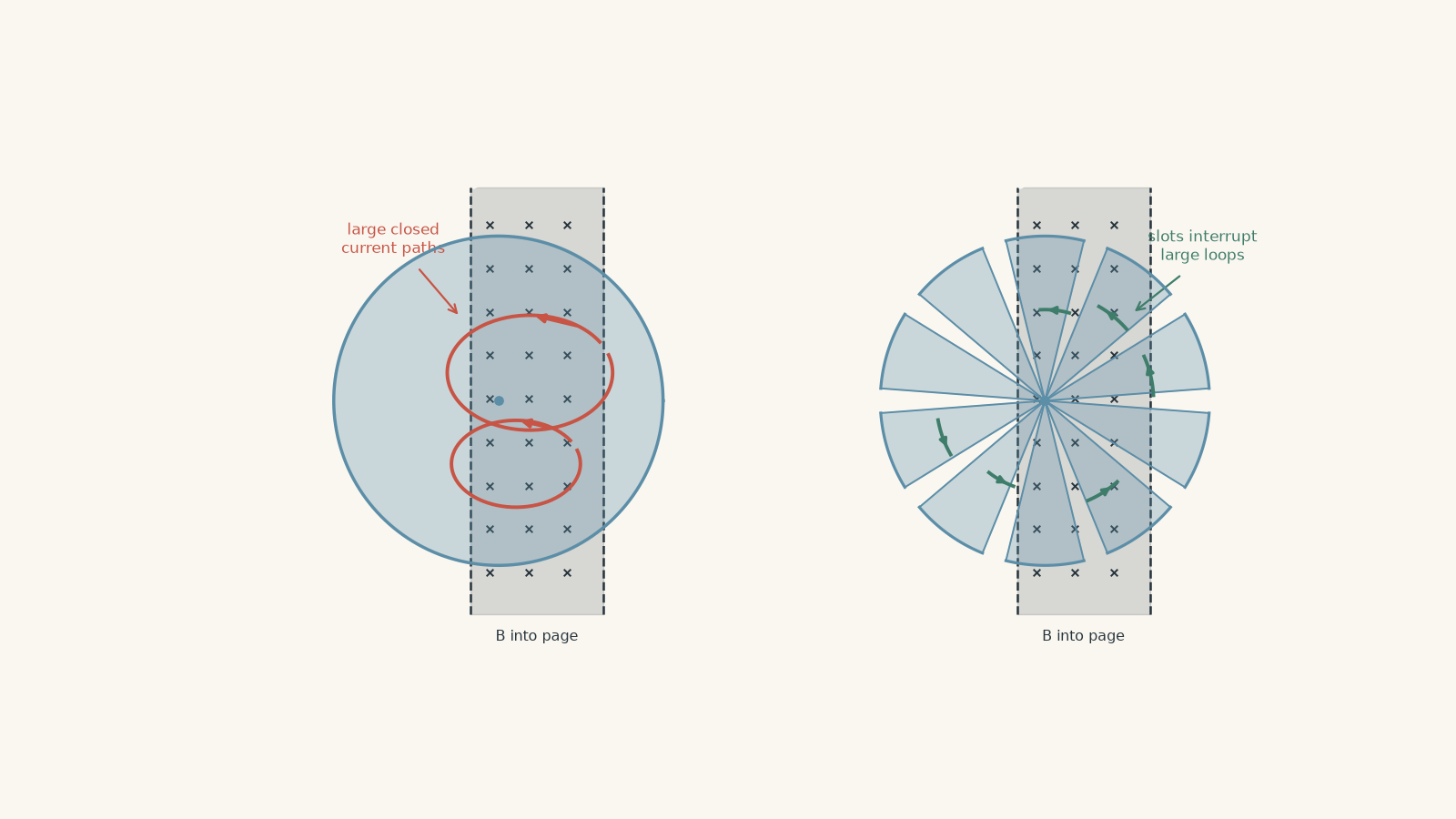
The magnetic field can still change through the metal. Faraday’s law has not disappeared.
What has changed is the current path.
The slots break large circulating loops and usually increase the effective resistance of the remaining paths. That reduces the eddy-current magnitude and therefore reduces the magnetic drag.
This distinction is useful in experimental questions. A smaller braking effect after cutting slots is evidence that circulating induced currents matter. It is not simply evidence that “there is less metal”.
08The most tempting misconception: Lenz’s law opposes motion
In magnetic braking problems, saying “Lenz’s law opposes motion” often gives the correct direction.
It is still an unsafe rule.
Consider a metal plate sitting completely still in a steady magnetic field. There is a magnetic field, but nothing is changing. There is no continuing eddy-current brake.
Now imagine a conductor translating through an ideal, perfectly uniform magnetic field while the magnetic flux through each relevant closed path stays constant. The simple flux-change model does not predict continuing eddy-current braking just because the conductor has a velocity.
What matters is changing flux.
Real magnetic brakes therefore use a localised or non-uniform magnetic field, relative motion past magnets, or another arrangement that produces changing magnetic flux within the conductor.
The better decision rule is:
- Identify a possible conducting path.
- Decide whether its magnetic flux is increasing or decreasing.
- Use Lenz’s law to find the induced field that opposes that change.
- Use the right-hand rule to find the induced current.
- Use the magnetic force on that current to determine the mechanical effect.
That takes slightly longer than chanting “opposes motion”, but it keeps working when the geometry becomes harder.
09Why the brake cannot hold something still
Suppose an eddy-current brake slows a rotating metal disc almost to rest.
Could it then keep the disc locked in position?
Not by eddy currents alone.
As the speed approaches zero, the rate of flux change approaches zero. The induced emf becomes smaller, the eddy currents become smaller, and the braking force becomes smaller.
At rest,
\[ \frac{\Delta\Phi_B}{\Delta t}=0 \]
so an ideal steady-field eddy-current brake produces no continuing induced emf.
That makes eddy-current brakes excellent for smooth, contactless slowing, but unsuitable as the only device for holding a stationary load. A real system that must stay still needs another mechanism, such as a mechanical brake or lock.
10Questions and solutions
Question 1
A conducting region in an aluminium plate is modelled as a loop of area \(0.015\text{ m}^2\) and resistance \(0.030\,\Omega\). As the plate enters a magnetic field directed into the page, the field through the loop increases uniformly from \(0\) to \(0.40\text{ T}\) in \(0.050\text{ s}\).
Calculate:
a. the average induced emf,
b. the induced current, and
c. the direction of the current.
Solution 1
The induced emf is \(0.12\text{ V}\), the current is \(4.0\text{ A}\), and the current is anticlockwise.
The tempting mistake is to decide the direction from the external field alone. Lenz’s law responds to the change in flux.
The change in magnetic flux is
\[ \Delta\Phi_B =A\Delta B =(0.015)(0.40) =0.0060\text{ Wb} \]
Using Faraday’s law,
\[ |\varepsilon| =\frac{|\Delta\Phi_B|}{\Delta t} =\frac{0.0060}{0.050} =0.12\text{ V} \]
Then, using Ohm’s law,
\[ I=\frac{\varepsilon}{R} =\frac{0.12}{0.030} =4.0\text{ A} \]
The magnetic flux into the page is increasing. The induced magnetic field must therefore point out of the page to oppose that increase.
The right-hand grip rule gives an anticlockwise current.
Question 2
A particular magnetic brake can be approximated over a certain speed range by the simple loop model
\[ \varepsilon=B\ell v \]
with constant magnetic field strength, geometry, and resistance.
The speed of the conductor is doubled.
Determine how this changes:
a. the induced emf,
b. the induced current,
c. the braking force, and
d. the rate of thermal energy production.
Explain why the force and power do not change by the same factor.
Solution 2
The emf doubles, the current doubles, the braking force doubles, and the thermal power becomes four times larger.
It is tempting to say that everything doubles because the speed doubles. The missed interaction is that power depends on both the force and the speed.
From
\[ \varepsilon=B\ell v \]
doubling \(v\) gives
\[ \varepsilon' =2\varepsilon \]
With constant resistance,
\[ I=\frac{\varepsilon}{R} \]
so
\[ I'=2I \]
The magnetic force is
\[ F=BI\ell \]
therefore
\[ F'=2F \]
But the mechanical braking power is
\[ P=Fv \]
Both \(F\) and \(v\) have doubled, so
\[ P'=(2F)(2v)=4Fv=4P \]
The electrical result agrees:
\[ P=I^2R \]
and therefore
\[ P'=(2I)^2R=4I^2R=4P \]
So a twofold increase in speed produces twice the drag force but four times the energy transfer per second in this simplified speed range.
Question 3
A uniform conducting disc has mass \(2.0\text{ kg}\) and radius \(0.20\text{ m}\). Its moment of inertia is
\[ I_{\text{rot}}=\frac{1}{2}MR^2 \]
The disc rotates through a fixed magnetic brake, slowing from \(50\text{ rad s}^{-1}\) to \(20\text{ rad s}^{-1}\).
During this interval, measurements show that \(36\text{ J}\) of thermal energy appears in the disc.
a. Calculate the decrease in the disc’s rotational kinetic energy.
b. Determine how much energy was transferred by other processes.
c. A student says, “The missing energy must have been stored in the permanent magnet.” Assess this claim.
Solution 3
The rotational kinetic energy decreases by \(42\text{ J}\), so \(6.0\text{ J}\) is transferred by other processes; there is no need to assign that energy to storage in the permanent magnet.
First calculate the moment of inertia:
\[ I_{\text{rot}} =\frac{1}{2}MR^2 =\frac{1}{2}(2.0)(0.20)^2 =0.040\text{ kg m}^2 \]
Rotational kinetic energy is
\[ E_k=\frac{1}{2}I_{\text{rot}}\omega^2 \]
where \(\omega\) is angular velocity in radians per second.
Initially,
\[ E_{k,i} =\frac{1}{2}(0.040)(50)^2 =50\text{ J} \]
Finally,
\[ E_{k,f} =\frac{1}{2}(0.040)(20)^2 =8.0\text{ J} \]
So the decrease is
\[ \Delta E_k =50-8.0 =42\text{ J} \]
Of this, \(36\text{ J}\) becomes thermal energy in the disc. The remaining energy transfer is
\[ 42-36=6.0\text{ J} \]
That \(6.0\text{ J}\) could be transferred through processes such as air resistance, bearing friction, or heating elsewhere in the apparatus.
The tempting claim is that because a magnet caused the braking force, the magnet must absorb the lost kinetic energy. That does not follow.
In normal eddy-current braking, induced currents dissipate mechanical energy as thermal energy. Conservation of energy only requires the full energy transfers to balance; it does not require the permanent magnet to act as an energy store.
Question 4
Two identical conducting discs begin with the same angular speed. Disc A is continuous. Disc B has several narrow radial slots cut through it.
Both pass through identical magnetic-field regions. Ignore the small difference in their moments of inertia caused by the removed material.
During the interval in which each disc slows from angular speed \(\omega_1\) to the same lower angular speed \(\omega_2\):
a. Which disc is expected to experience the stronger magnetic braking torque?
b. If eddy-current braking is the only significant energy-transfer process during that interval, which disc converts more mechanical energy into thermal energy in total?
c. Explain how your answers to a. and b. can both be correct.
Solution 4
Disc A experiences the stronger braking torque, but both discs convert the same total amount of mechanical energy into thermal energy while slowing between the same two angular speeds.
A common first answer is that the stronger brake must produce more heat in total. That confuses the rate of energy transfer with the total energy transferred.
Disc A is continuous, so large circulating eddy-current paths are available. Disc B’s radial slots interrupt many of those paths, increasing their effective resistance or preventing them entirely.
Disc A therefore develops larger eddy currents and a stronger magnetic braking torque.
However, both discs begin at \(\omega_1\) and finish at \(\omega_2\), and we are told to treat their moments of inertia as equal.
Their loss of rotational kinetic energy is therefore the same:
\[ \Delta E_k =\frac{1}{2}I_{\text{rot}}\left(\omega_1^2-\omega_2^2\right) \]
If eddy-current heating is the only significant energy-transfer process, conservation of energy requires that same \(\Delta E_k\) to become thermal energy in each case.
Disc A transfers the energy at a greater rate, so it reaches \(\omega_2\) sooner.
Disc B has weaker braking, so the same energy transfer occurs over a longer time.
The key constraint is the fixed initial and final mechanical energies. Brake strength controls how rapidly the energy is removed, not how much energy must be removed to reach the specified final speed.
Question 5
A rectangular conducting loop is pulled to the right at constant speed through a finite region of uniform magnetic field directed into the page.
The loop first enters the field, later becomes completely enclosed within the uniform field region, and finally exits it.
The loop has width \(0.40\text{ m}\) in the direction of motion. Its vertical side has length \(0.25\text{ m}\). The field strength is \(0.80\text{ T}\), the loop resistance is \(0.20\,\Omega\), and its speed is held constant at \(3.0\text{ m s}^{-1}\).
Assume sharp field boundaries and neglect self-inductance.
a. State the direction of the induced current while the loop enters the field.
b. State the current while the loop is completely inside the uniform field.
c. State the direction of the induced current while the loop exits the field.
d. Determine the magnetic drag force while it is entering or exiting.
e. Calculate the total thermal energy produced during both boundary crossings.
f. A student argues: “The current reverses on exit, so the magnetic force must reverse too. The field gives back the energy removed during entry.” Explain precisely why this is wrong.
Solution 5
The current is anticlockwise on entry, zero while the loop is completely inside the ideal uniform field, and clockwise on exit; nevertheless, the magnetic force opposes the motion during both entry and exit. The drag force is \(0.60\text{ N}\), and the total thermal energy produced is \(0.48\text{ J}\).
The tempting argument focuses on the current reversal but forgets that a different side of the loop is interacting with the field during exit. Both the current direction and the relevant geometry matter.
During entry, the magnetic flux into the page increases. Lenz’s law requires an induced field out of the page, so the current is anticlockwise.
Once the entire loop moves inside the uniform field, its area, orientation, and magnetic field are constant. Therefore,
\[ \frac{\Delta\Phi_B}{\Delta t}=0 \]
and the idealised induced emf and current are zero.
During exit, the flux into the page decreases. The induced field must now point into the page to oppose that decrease, requiring a clockwise current.
For either boundary crossing, the magnitude of the motional emf is
\[ \varepsilon =B\ell v =(0.80)(0.25)(3.0) =0.60\text{ V} \]
The induced current magnitude is
\[ I =\frac{\varepsilon}{R} =\frac{0.60}{0.20} =3.0\text{ A} \]
The magnetic force magnitude is
\[ F =BI\ell =(0.80)(3.0)(0.25) =0.60\text{ N} \]
The force acts to the left, opposite the loop’s rightward motion, during both entry and exit.
Each boundary crossing lasts for the time required for the loop’s \(0.40\text{ m}\) width to pass the boundary:
\[ t =\frac{d}{v} =\frac{0.40}{3.0} =0.133\text{ s} \]
The rate of thermal energy production is
\[ P =I^2R =(3.0)^2(0.20) =1.8\text{ W} \]
So the thermal energy produced during one crossing is
\[ E =Pt =(1.8)(0.133) \approx0.24\text{ J} \]
There are two crossings, giving
\[ E_{\text{total}} =2(0.24) =0.48\text{ J} \]
The student’s argument fails because reversing the loop current does not automatically reverse the net force.
On entry, one vertical side of the loop is the important current-carrying section inside the field. On exit, the opposite vertical side is the section that remains in the field. The current around the whole loop reverses, but the combination of current direction and magnetic-field geometry still produces a force opposite the motion.
There is also an energy constraint. The loop is being pulled at constant speed, so an external agent must do positive work against the magnetic drag. That work becomes thermal energy in the loop.
If the magnetic force instead accelerated the loop on exit strongly enough to return all the entry energy while resistance was still producing heat, the energy balance would fail.
This is the deeper reason Lenz’s law is reliable: the induced response is constrained by conservation of energy.
11Where this idea leads next
Eddy-current braking is one example of a broader rule: whenever induction creates a current, the induced effect pushes back against the change that created it.
The same energy logic appears in a DC motor. As the motor spins, it develops a back emf that opposes the applied voltage. It also appears in an AC generator, where continuous changes in magnetic flux produce an alternating emf.
So the next useful step is not another direction rule. It is learning to see Faraday’s law, Lenz’s law, magnetic force, and conservation of energy as one connected model rather than four separate facts.