
AC Induction Motors: Rotating Fields, Rotor Currents and Slip
Learn how rotating magnetic fields induce rotor currents and produce torque in an AC induction motor. Understand synchronous speed, slip, load changes, and generating operation.
A motor is connected to AC, but the rotating part has no battery, no brushes, and no direct electrical connection to the power supply. Somehow, current appears in the rotor anyway, and that current produces enough torque to turn a load.
Here is the key prediction. Suppose the magnetic field inside the motor rotates at 1500 rpm. Will the rotor eventually catch it and also rotate at exactly 1500 rpm?
It seems as though it should. But if it did, the motor would lose the very effect that produces its torque.
That apparent contradiction is the useful idea behind an AC induction motor.
01The two jobs inside an induction motor
A simple induction motor has two main parts:
- the stator, which stays still and contains the AC windings,
- the rotor, which turns inside the stator.
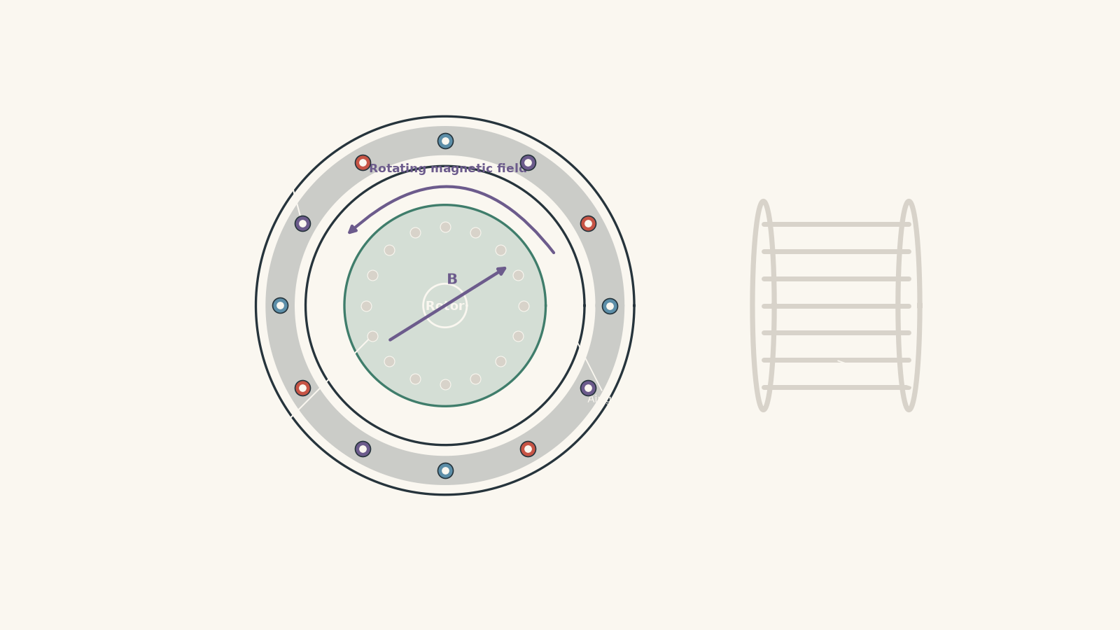
In a common squirrel-cage induction motor, the rotor contains conducting bars joined at both ends by conducting rings. Together, the bars and end rings form closed conducting loops.
There is no need to feed current into these bars directly.
Instead, the stator produces a moving magnetic field. That field changes the magnetic flux through the rotor loops, so an emf is induced. Because the loops are closed, an induced current flows.
Then the magnetic field exerts a force on that current.
So the chain is:
\[ \text{AC in stator} \rightarrow \text{rotating magnetic field} \rightarrow \text{induced rotor emf} \rightarrow \text{rotor current} \rightarrow \text{magnetic force} \rightarrow \text{torque} \]
Missing one of those links is the source of most induction-motor confusion.
02How can stationary coils make a rotating magnetic field?
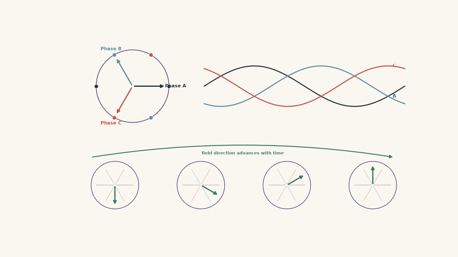
Imagine three people standing equally spaced around a circular table. Each person raises and lowers one hand smoothly, but they do it out of step with each other. The first reaches maximum height, then the second, then the third.
If you watched only where the highest hand was, the peak would seem to travel around the table.
A three-phase stator does something similar with magnetic fields.
The analogy is useful because both the position and the timing matter. It breaks down because no magnetic field is literally being handed from one coil to another. The actual field is the vector sum of the fields produced by all the windings.
One AC winding is not enough for this simple picture
An AC current reverses direction periodically. A single stator winding therefore produces a magnetic field whose strength and polarity alternate.
Its axis stays in the same place. The field does not simply sweep around the motor.
Now put three windings around the stator, with their magnetic axes separated in space. Supply them with three AC currents that are also separated in time by one-third of a cycle, or \(120^\circ\).
At any instant, all three windings contribute to the magnetic field.
A short time later, their current values have changed. The direction of the combined field has changed too.
For a balanced three-phase supply, the result is a magnetic field of approximately constant magnitude whose direction rotates smoothly around the stator.
This guide uses the standard three-phase model because it exposes the physics clearly. Single-phase induction motors can also operate, but they require an additional method for establishing a starting rotating field.
03How fast does the magnetic field rotate?
The speed of the rotating stator field is called the synchronous speed.
It depends on two things:
- the AC supply frequency,
- the number of magnetic poles produced by the stator winding.
The synchronous speed is
\[ n_s=\frac{120f}{P} \]
where:
- \(n_s\) is the synchronous speed in revolutions per minute, or rpm,
- \(f\) is the AC supply frequency in hertz, or Hz,
- \(P\) is the total number of magnetic poles.
For example, a 50 Hz supply and a four-pole stator give
\[ n_s=\frac{120(50)}{4}=1500\text{ rpm} \]
The magnetic field therefore completes 1500 revolutions each minute.
Notice what this equation does not contain: the rotor speed.
A heavier mechanical load can slow the rotor, but it does not make the stator’s rotating field gradually slow with it. If the supply frequency and number of poles stay fixed, the synchronous speed stays fixed.
Worked example: Find the speed of the rotating field
A three-phase induction motor is connected to a 50 Hz AC supply. Its stator produces six magnetic poles. Calculate the synchronous speed of the magnetic field.
Step 1
The supply frequency is \(f=50\text{ Hz}\), and the motor has \(P=6\) poles.
Step 2
\[ n_s=\frac{120f}{P} =\frac{120(50)}{6} =1000\text{ rpm} \]
Step 3
The stator itself remains stationary, but the combined magnetic field produced by its windings rotates at \(1000\text{ rpm}\).
That does not mean the rotor will also turn at exactly \(1000\text{ rpm}\). We now need to see why.
04Why current appears in the rotor
Start with the rotor stationary.
The stator field is rotating past it, so the magnetic flux through a closed conducting path in the rotor is continually changing.
Faraday’s law tells us that a changing magnetic flux induces an emf:
\[ \mathcal{E}=-\frac{\Delta\Phi}{\Delta t} \]
where:
- \(\mathcal{E}\) is the induced emf in volts,
- \(\Phi\) is magnetic flux in webers,
- \(\Delta\Phi/\Delta t\) is the rate of change of magnetic flux.
The minus sign represents Lenz’s law: the induced effect acts in a direction that opposes the change that produced it.
This is the same basic induction principle used in an AC generator, but the geometry and purpose are different. In a generator, mechanical motion is deliberately used to produce an emf. In an induction motor, the stator’s moving field induces currents in the rotor, and those currents then help produce mechanical motion.
The rotor needs a closed circuit
An emf alone is not enough.
Because the squirrel-cage bars are joined by end rings, there are closed conducting paths through the rotor. The induced emf can therefore drive an induced current.
Now we have a current-carrying conductor sitting inside a magnetic field.
That is exactly the situation needed for the motor effect.
For a straight conductor,
\[ F=BIL\sin\theta \]
where:
- \(F\) is magnetic force in newtons,
- \(B\) is magnetic flux density in tesla,
- \(I\) is current in amperes,
- \(L\) is the conductor length in metres,
- \(\theta\) is the angle between the conductor and the magnetic field.
Forces on rotor bars around the rotor combine to produce a turning effect: torque.
05Which way does the rotor turn?
Suppose the stator field rotates clockwise.
What direction should the rotor turn?
Lenz’s law gives the quickest answer. The induced rotor currents produce effects that oppose the relative motion responsible for the induction.
The rotor therefore develops torque in the same direction as the rotating stator field.
That does not mean it is trying to oppose the field’s direction. It is trying to reduce how quickly the field sweeps past the rotor.
If the rotor accelerates clockwise, the relative motion becomes smaller.
This is one place where the sentence “Lenz’s law opposes motion” can cause trouble. Lenz’s law does not automatically mean the rotor must move in the opposite direction. It means the induced effect opposes the change in magnetic flux that produced it.
Here, following the field reduces that change.
06Why the rotor can never quite catch the field
Return to our original prediction.
Imagine a four-pole motor on a 50 Hz supply. Its magnetic field rotates at \(1500\text{ rpm}\).
Suppose the rotor accelerates from rest:
- at \(0\text{ rpm}\), the field sweeps rapidly past the rotor,
- at \(1000\text{ rpm}\), the field still gains \(500\text{ rpm}\) on it,
- at \(1450\text{ rpm}\), the difference is only \(50\text{ rpm}\).
Now imagine the rotor reaches exactly \(1500\text{ rpm}\).
Relative to the rotor, the magnetic-field pattern would no longer move around it.
There would be no continuing change of magnetic flux caused by the field sweeping past the rotor. In the idealised model, the induced rotor emf would fall to zero. The rotor current would fall to zero, so the electromagnetic torque would also fall to zero.
A motor under load needs electromagnetic torque.
Therefore, an induction motor operating as a motor must normally rotate slightly below synchronous speed.
That difference is called slip.
07Slip measures how far the rotor lags behind
Slip can be written as a fraction:
\[ s=\frac{n_s-n_r}{n_s} \]
where:
- \(s\) is slip,
- \(n_s\) is synchronous speed,
- \(n_r\) is rotor speed.
To express it as a percentage,
\[ s(\%)=\frac{n_s-n_r}{n_s}\times100 \]
Suppose \(n_s=1500\text{ rpm}\) and \(n_r=1440\text{ rpm}\).
Then
\[ s=\frac{1500-1440}{1500}=0.040 \]
so the slip is \(4.0\%\).
The field is only gaining \(60\text{ rpm}\) on the rotor, but that relative motion is crucial. It maintains the changing flux that induces the rotor currents.
Worked example: Speed, slip, and rotor induction
A four-pole induction motor operates from a 50 Hz supply. Under a particular load, its rotor turns at \(1440\text{ rpm}\).
Calculate:
- the synchronous speed,
- the slip as a percentage,
- the frequency of the changing magnetic field experienced by the rotor.
Step 1
Here \(f=50\text{ Hz}\) and \(P=4\).
\[ n_s=\frac{120f}{P} =\frac{120(50)}{4} =1500\text{ rpm} \]
Step 2
\[ s=\frac{n_s-n_r}{n_s} =\frac{1500-1440}{1500} =0.040 \]
Therefore,
\[ s=4.0\% \]
Step 3
When the rotor is stationary, it experiences the stator field changing at the supply frequency of \(50\text{ Hz}\).
At \(4.0\%\) slip, the relative magnetic pattern passes the rotor at \(4.0\%\) of that rate.
So the rotor-current frequency is
\[ f_r=sf=(0.040)(50)=2.0\text{ Hz} \]
where \(f_r\) is the frequency of the induced rotor current.
Step 4
The stator field still rotates at \(1500\text{ rpm}\), while the rotor rotates at \(1440\text{ rpm}\). Because the rotor nearly keeps up, it experiences only a slowly changing field, giving a rotor-current frequency of \(2.0\text{ Hz}\).
The motor does not need large relative motion once it is already spinning under this load. It needs enough slip to induce the currents required for the necessary torque.
08What happens when the mechanical load increases?
Suppose an induction motor is running steadily and you increase the resisting torque on its shaft.
A tempting prediction is that the motor simply “tries harder” while remaining at exactly the same speed.
The important mechanism is more interesting.
The added load first causes the rotor to slow slightly.
That means the rotating magnetic field now moves past the rotor more quickly. The rate of flux change in the rotor increases, so a larger emf can be induced.
The resulting change in rotor current allows the electromagnetic torque to increase until a new operating condition is reached.
So, in the normal operating region:
\[ \text{more load} \rightarrow \text{slightly lower rotor speed} \rightarrow \text{greater slip} \rightarrow \text{stronger induction effect} \rightarrow \text{greater electromagnetic torque} \]
This is a useful self-adjusting feature of the induction motor.
There is an important precision here. Motor torque is not simply proportional to slip for every possible speed. Rotor resistance, inductive reactance, magnetic saturation, and the motor’s design all affect the full torque-speed curve. For HSC reasoning, the safe statement is that increasing load from a normal operating point causes a small speed decrease and increased slip, allowing the motor to develop the additional torque required.
09The most tempting wrong model: the field physically drags the rotor
It is easy to picture the rotating magnetic field as an invisible hand grabbing the rotor and dragging it around.
That picture predicts the right direction but hides the physics.
The rotor is not mechanically attached to the field.
The essential sequence is:
- relative motion creates changing rotor flux,
- changing flux induces an emf,
- the closed rotor circuit carries current,
- the stator field acts on that current,
- magnetic forces produce torque.
If the induction stage disappears, the torque disappears too.
That is exactly why synchronous speed is such an important boundary.
10Slip is not the same idea as back emf
Students sometimes mix induction-motor slip with back emf in a DC motor because both produce a useful self-regulating effect.
There is a similarity:
- as a motor’s operating condition changes, electromagnetic induction changes the current or torque response.
But the mechanisms are not identical.
In a DC motor, rotation of the armature produces an emf that opposes the supply voltage.
In a squirrel-cage induction motor, the rotor receives no external supply voltage. Its current exists because the rotating stator field moves relative to it. As that relative motion becomes smaller, the induced rotor emf becomes smaller.
Keep the mechanisms separate even though both rely on electromagnetic induction.
11Reversing the motor
Three-phase induction motors have another useful property.
Swap any two phases of the stator supply, and the phase sequence reverses.
The sequence might change from
\[ A\rightarrow B\rightarrow C \]
to
\[ A\rightarrow C\rightarrow B \]
The rotating magnetic field then rotates in the opposite direction.
The rotor torque reverses with it.
Again, there is no need to reverse current through the rotor manually. Its current is induced according to the new relative motion and magnetic-field direction.
12What if the rotor goes faster than synchronous speed?
This is the boundary case that makes the whole model clearer.
Suppose the field rotates clockwise at \(1500\text{ rpm}\), but an external machine forces the rotor clockwise at \(1530\text{ rpm}\).
Now the rotor is overtaking the field.
The relative motion has reversed.
The induced rotor currents therefore reverse in the way required by Lenz’s law, and the electromagnetic torque acts against the externally driven rotor.
Mechanical energy can now be transferred into electrical energy.
The same induction machine is operating as an induction generator.
So synchronous speed is not just “the speed the rotor almost reaches”. It separates two operating regimes:
| Rotor condition | Relative motion | Electromagnetic effect |
|---|---|---|
| \(n_r<n_s\) | Field overtakes rotor | Torque drives rotor forward |
| \(n_r=n_s\) | No relative field motion in ideal model | Rotor induction and torque fall to zero |
| \(n_r>n_s\) | Rotor overtakes field | Torque opposes rotor; generating operation is possible |
That table is a much better model than memorising “an induction motor runs below synchronous speed”.
13Questions and solutions
Question 1
A six-pole induction motor is connected to a 50 Hz AC supply. Its rotor turns at \(960\text{ rpm}\).
Calculate:
a. the synchronous speed,
b. the slip as a percentage,
c. why the rotor must run below the synchronous speed while supplying a mechanical load.
Solution 1
The synchronous speed is \(1000\text{ rpm}\), and the slip is \(4.0\%\). The rotor must remain below synchronous speed so that relative motion between the rotating field and rotor continues to induce the currents needed for torque.
For part a,
\[ n_s=\frac{120f}{P} =\frac{120(50)}{6} =1000\text{ rpm} \]
For part b,
\[ s=\frac{n_s-n_r}{n_s} =\frac{1000-960}{1000} =0.040 \]
Therefore,
\[ s=4.0\% \]
For part c, the rotor bars form closed conducting paths. Because the magnetic field rotates faster than the rotor, the rotor experiences changing magnetic flux. An emf and current are induced, and the stator magnetic field exerts forces on these currents to produce torque.
The tempting idea is that the best motor should eliminate the speed difference completely. But at \(n_r=n_s\), the idealised rotor sees no field pattern moving relative to it, so the induced rotor emf and torque disappear. A loaded induction motor therefore requires non-zero slip.
Question 2
A four-pole induction motor operates from a 50 Hz supply. Initially, its rotor turns at \(1455\text{ rpm}\). A larger mechanical load is applied, and the steady rotor speed becomes \(1410\text{ rpm}\).
Calculate the slip and rotor-current frequency before and after the load increase. Then explain why the speed decrease helps the motor respond to the greater load.
Solution 2
The slip increases from \(3.0\%\) to \(6.0\%\), and the rotor-current frequency increases from \(1.5\text{ Hz}\) to \(3.0\text{ Hz}\). The larger slip increases the rate at which the stator field sweeps past the rotor, strengthening the induction effect needed to develop more torque.
First find synchronous speed:
\[ n_s=\frac{120f}{P} =\frac{120(50)}{4} =1500\text{ rpm} \]
Initially,
\[ s_1=\frac{1500-1455}{1500} =\frac{45}{1500} =0.030 \]
so
\[ s_1=3.0\% \]
and
\[ f_{r1}=s_1f=(0.030)(50)=1.5\text{ Hz} \]
After the load increases,
\[ s_2=\frac{1500-1410}{1500} =\frac{90}{1500} =0.060 \]
so
\[ s_2=6.0\% \]
and
\[ f_{r2}=s_2f=(0.060)(50)=3.0\text{ Hz} \]
The tempting route is to assume that the whole rotating magnetic field slows when the shaft slows. It does not. The synchronous speed remains \(1500\text{ rpm}\) because the frequency and pole number have not changed.
Instead, the rotor has fallen farther behind the field. The increased relative motion causes more rapid flux change in the rotor circuits. This allows a larger induced emf and a changed rotor current, so the motor can develop the greater torque required by the larger mechanical load.
The exact torque-current relationship depends on the motor’s electrical characteristics, so it would be too strong to claim that doubling slip must always double torque.
Question 3
Two identical four-pole induction motors are connected to separate 50 Hz supplies.
Motor A has its rotor held stationary.
Motor B has its rotor externally driven at \(1200\text{ rpm}\) in the same direction as its rotating stator field.
Assume the magnetic-field strength is the same in both motors.
a. Compare the rate at which the rotating field moves relative to each rotor.
b. Using a simple flux-change model, compare their induced rotor emfs.
c. Explain why you cannot automatically conclude that the rotor currents have exactly the same ratio as the induced emfs.
Solution 3
Motor A experiences five times the relative rotational rate of Motor B, so the simple induction model predicts an induced emf five times as large in Motor A. The rotor currents, however, need not have an exact \(5:1\) ratio because rotor impedance also changes with the frequency of the induced current.
Both motors have
\[ n_s=\frac{120(50)}{4}=1500\text{ rpm} \]
For Motor A, the rotor is stationary, so the relative rate is
\[ 1500-0=1500\text{ rpm} \]
For Motor B,
\[ 1500-1200=300\text{ rpm} \]
Therefore,
\[ \frac{\text{relative rate for A}}{\text{relative rate for B}} = \frac{1500}{300} =5 \]
If the same magnetic pattern passes otherwise identical rotor loops five times more rapidly, the rate of flux change is five times greater. From Faraday’s law,
\[ |\mathcal{E}|\propto\left|\frac{\Delta\Phi}{\Delta t}\right| \]
so the simplified model predicts
\[ \frac{\mathcal{E}_A}{\mathcal{E}_B}=5 \]
The tempting next step is to use \(I=V/R\) and claim \(I_A=5I_B\). That assumes the rotor circuit behaves as a fixed resistance.
An induction motor’s rotor also has inductive effects. Motor A experiences the field changing at a higher frequency, so its rotor impedance is not necessarily the same as Motor B’s. The emf comparison follows directly from the simplified flux-change model, but an exact current ratio would require more information about the rotor impedance.
This distinction matters because “more induced emf” and “the same multiple of current” are not automatically equivalent statements in an AC circuit.
Question 4
A four-pole induction motor is connected to a 50 Hz supply and is rotating steadily at \(1470\text{ rpm}\) clockwise. Its stator field therefore rotates clockwise.
An electrician reverses the phase sequence instantaneously by swapping two supply phases. Assume the rotor’s mechanical speed cannot change significantly during the first instant after switching.
a. State the new synchronous speed, including its direction.
b. Calculate the magnitude of the initial relative rotational speed between the rotor and the new rotating field.
c. Determine the magnitude of the corresponding slip.
d. Calculate the initial rotor-current frequency immediately after the reversal.
e. Explain the direction of the electromagnetic torque.
Solution 4
Immediately after the phase reversal, the stator field rotates at \(1500\text{ rpm}\) anticlockwise while the rotor is still moving at \(1470\text{ rpm}\) clockwise. Their relative rotational speed is therefore \(2970\text{ rpm}\), the slip magnitude is \(1.98\), the rotor-current frequency is approximately \(99\text{ Hz}\), and the electromagnetic torque acts anticlockwise.
The synchronous-speed magnitude is unchanged:
\[ |n_s|=\frac{120(50)}{4}=1500\text{ rpm} \]
Take clockwise as positive. Before switching,
\[ n_r=+1470\text{ rpm} \]
After reversing the phase sequence,
\[ n_s=-1500\text{ rpm} \]
For part b, the relative rate is
\[ n_s-n_r=-1500-1470=-2970\text{ rpm} \]
so its magnitude is
\[ 2970\text{ rpm} \]
The tempting mistake is to calculate \(1500-1470=30\text{ rpm}\). That would be correct only if the field and rotor were still travelling in the same direction. After the phase reversal, they move past each other in opposite directions, so their speed magnitudes add.
For part c,
\[ s=\frac{n_s-n_r}{n_s} =\frac{-1500-1470}{-1500} =1.98 \]
So the slip magnitude is
\[ |s|=1.98 \]
or \(198\%\).
This is possible because ordinary motor-operation slip values between 0 and 1 are not a universal mathematical limit. Here the rotor is initially travelling opposite to the newly reversed field.
For part d,
\[ f_r=|s|f =(1.98)(50) =99\text{ Hz} \]
The rotor therefore initially experiences a rapidly changing magnetic field.
For part e, Lenz’s law tells us the induced effect acts to reduce the large relative motion. The new field rotates anticlockwise, so the electromagnetic torque acts anticlockwise. It first brakes the clockwise rotor and can then accelerate it anticlockwise.
It would be unsafe to conclude from the large slip alone that the torque must be exactly some fixed multiple of its previous value. At such a high rotor frequency, rotor reactance and the motor’s full torque-speed behaviour matter.
Question 5
A four-pole induction machine remains connected to a 50 Hz three-phase supply throughout the following process.
A mechanical device attached to its shaft controls the rotor speed.
Initially, the rotor turns in the same direction as the stator field at \(1470\text{ rpm}\). The external device then drives it gradually through \(1500\text{ rpm}\) and up to \(1530\text{ rpm}\).
Assume losses are negligible unless stated otherwise.
a. At \(1470\text{ rpm}\), state the direction of electromagnetic torque and the main direction of energy transfer.
b. At exactly \(1500\text{ rpm}\), state what happens to the induced rotor emf, rotor current, and electromagnetic torque in the idealised model.
c. At \(1530\text{ rpm}\), determine the slip and explain the direction of electromagnetic torque and energy transfer.
d. A resisting mechanical load is now connected to the shaft and the external driving device is removed. Describe what happens as the rotor passes from above to below synchronous speed. Explain why the direction of electromagnetic energy transfer changes even though the stator phase sequence has never been reversed.
Solution 5
Below synchronous speed the machine operates as a motor; at synchronous speed the idealised rotor induction and electromagnetic torque vanish; above synchronous speed the electromagnetic torque reverses and the machine can return electrical energy to the supply. The change is controlled by the sign of the relative motion between the rotor and the rotating magnetic field, not by any change in stator phase sequence.
First find the synchronous speed:
\[ n_s=\frac{120(50)}{4}=1500\text{ rpm} \]
For part a, at \(1470\text{ rpm}\),
\[ s=\frac{1500-1470}{1500} =0.020 \]
so the slip is \(+2.0\%\).
The stator field is overtaking the rotor. The resulting induced currents experience magnetic forces that produce torque in the direction of rotation, tending to make the rotor catch the field.
Ignoring losses, the main energy transfer is therefore
\[ \text{electrical energy} \rightarrow \text{mechanical energy} \]
This is ordinary induction-motor operation.
For part b, at exactly
\[ n_r=n_s=1500\text{ rpm} \]
the rotor moves with the rotating magnetic-field pattern.
In the idealised model, there is no relative motion between the rotor and that pattern, so there is no changing flux caused by the field sweeping past the rotor. Therefore,
\[ \mathcal{E}_{\text{rotor}}=0 \]
which gives zero induced rotor current and hence zero electromagnetic torque.
The tempting prediction is that synchronous speed should be the motor’s strongest or most efficient operating condition because the rotor has finally “caught” the field. The exact constraint that changes the result is that catching the field removes the relative motion required for induction.
For part c, at \(1530\text{ rpm}\),
\[ s=\frac{1500-1530}{1500} =-0.020 \]
so
\[ s=-2.0\% \]
The negative slip tells us that the rotor now overtakes the magnetic field.
The direction of relative motion has reversed, so the induced rotor currents reverse in the way required by Lenz’s law. The electromagnetic torque now opposes the rotor’s rotation rather than driving it forward.
The external mechanical device must do work against this electromagnetic torque. That mechanical energy can be converted into electrical energy and transferred back through the stator circuit.
The machine is now operating as an induction generator:
\[ \text{mechanical energy} \rightarrow \text{electrical energy} \]
For part d, once the external drive is removed, the resisting load and the electromagnetic generating torque cause the rotor to slow while it remains above \(1500\text{ rpm}\).
As it approaches synchronous speed from above, the magnitude of the relative motion decreases. The induced rotor emf, rotor current, and generating torque therefore approach zero in the idealised model.
At exactly \(1500\text{ rpm}\), the electromagnetic torque is zero.
The resisting mechanical load still acts, so the rotor continues to slow below synchronous speed.
Now the stator field begins overtaking the rotor instead of the rotor overtaking the field. That reverses the relevant relative motion, so the induced rotor currents change accordingly and the electromagnetic torque acts forward.
Electrical energy is once again taken from the supply and transferred towards the mechanical system.
Eventually, a new operating speed below synchronous speed can be reached where the motor’s electromagnetic torque balances the resisting load.
The difficult point is that nothing has happened to the stator field’s direction. It has rotated the same way at \(1500\text{ rpm}\) throughout.
What changed was which one was overtaking the other.
That gives a compact rule for the whole topic: an induction machine’s behaviour is determined by the relative motion between the rotor and the rotating magnetic field. Once that idea is secure, torque-speed curves, induction generators, and more detailed AC motor behaviour become much easier to reason about.