
Electric Motors and Back EMF: HSC Physics Practice Exam
Test your understanding of electric motors and back emf with this original 32-mark HSC Physics practice paper. Includes timed exam-style questions, fully worked solutions, and a detailed marking guide covering the 2025 syllabus scope.
This original tutorgum practice paper tests the specified Physics 11-12 (2025) syllabus content on electric motors and back emf. It is a focused topic assessment, not a full-course exam or an official, endorsed, past, or predicted NESA paper.
01Exam instructions
Total marks: 32
Suggested working time: 50 minutes
Reading time: 5 minutes
Permitted equipment: Scientific calculator, ruler, pens, and pencils. No notes or internet resources.
Assessed scope
This paper covers:
- AC induction motors: rotating magnetic fields, induced rotor currents, and torque production.
- Simple brushed DC motors: brushes, split-ring commutators, torque, and continuous rotation.
- Back emf in DC motors: its origin, relationship with rotational speed, effects on current, and energy transformations.
- Brushless DC motors: electromagnetic induction, rotor-position detection, electronic commutation, and torque production in the specified arrangement.
Exclusions
This paper does not assess generators, transformers, electromagnetic braking, detailed electronic circuit design, or advanced mathematical models of electric motors. Torque is assessed qualitatively rather than through complex torque calculations.
For Question 5, assume a sensorless, three-phase brushless DC motor. Its controller uses the emf induced in an unpowered stator winding to estimate rotor position. Not every brushless DC motor uses this particular sensing arrangement.
All numerical calculations use idealised conditions where specified. Show your working, include units, and give numerical answers to an appropriate number of significant figures.
The paper follows the supplied 2025 syllabus edition, rather than the 2017 Physics syllabus. NESA lists implementation of the 2025 syllabus from 2027, with the first HSC examination scheduled for 2028. See the NESA Physics 11-12 Syllabus (2025).【turn999310view0】
02Questions
Question 1 (6 marks)
An AC induction motor consists of a stator containing three windings connected to a three-phase AC supply and a squirrel-cage rotor. The rotor consists of conducting bars connected at both ends by conducting rings.
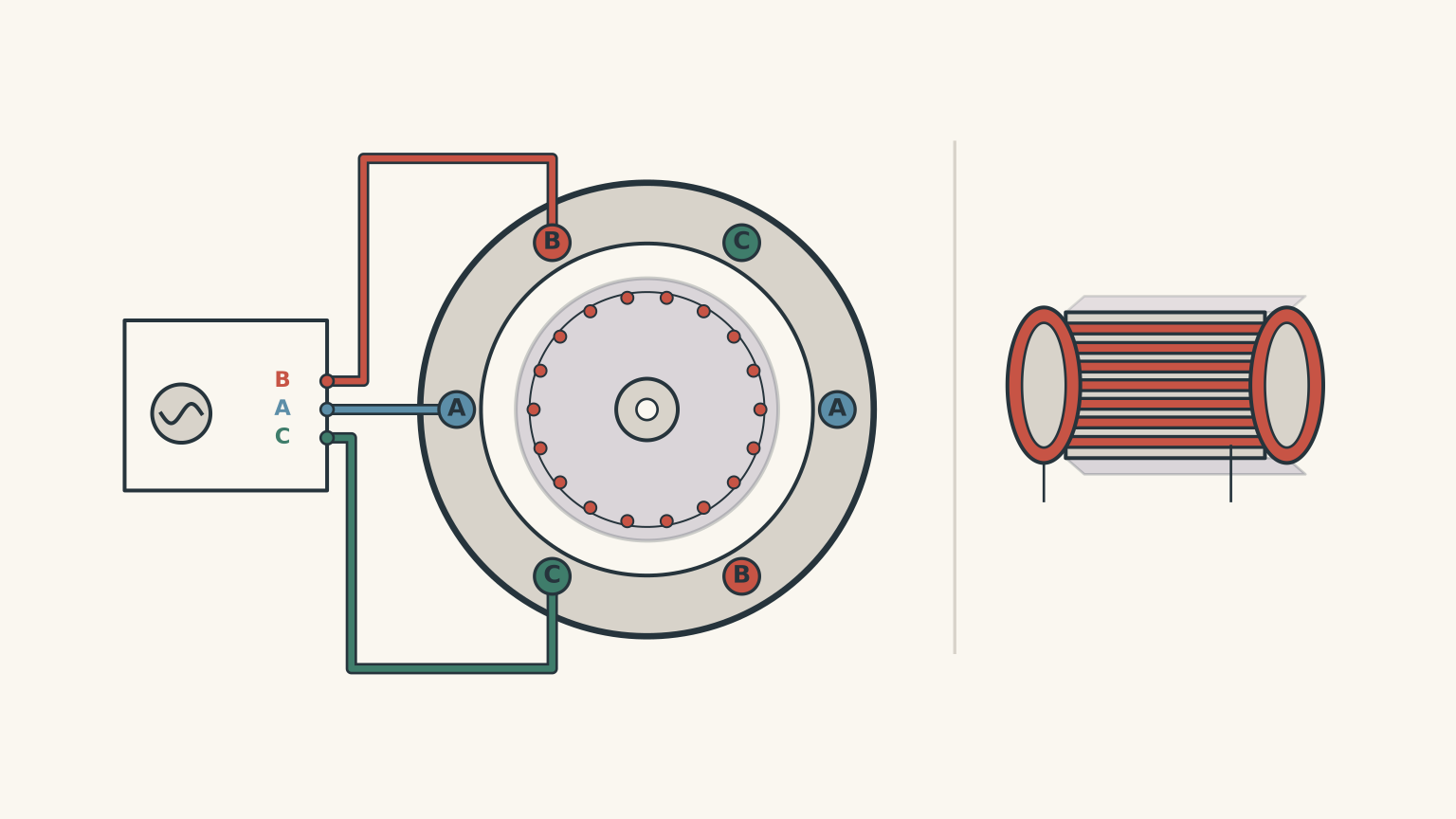
(a) Describe how the three-phase AC supply produces a rotating magnetic field in the stator. (2 marks)
(b) Explain how the rotating magnetic field produces currents in the rotor and how these currents produce torque. (3 marks)
(c) State what would happen to the induced rotor current and the motor’s torque if the rotor reached exactly the same angular speed as the rotating magnetic field. (1 mark)
Question 2 (6 marks)
A simple brushed DC motor contains a rectangular conducting coil mounted on a rotating shaft between two fixed magnetic poles. The coil is connected to a DC supply through brushes and a split-ring commutator.
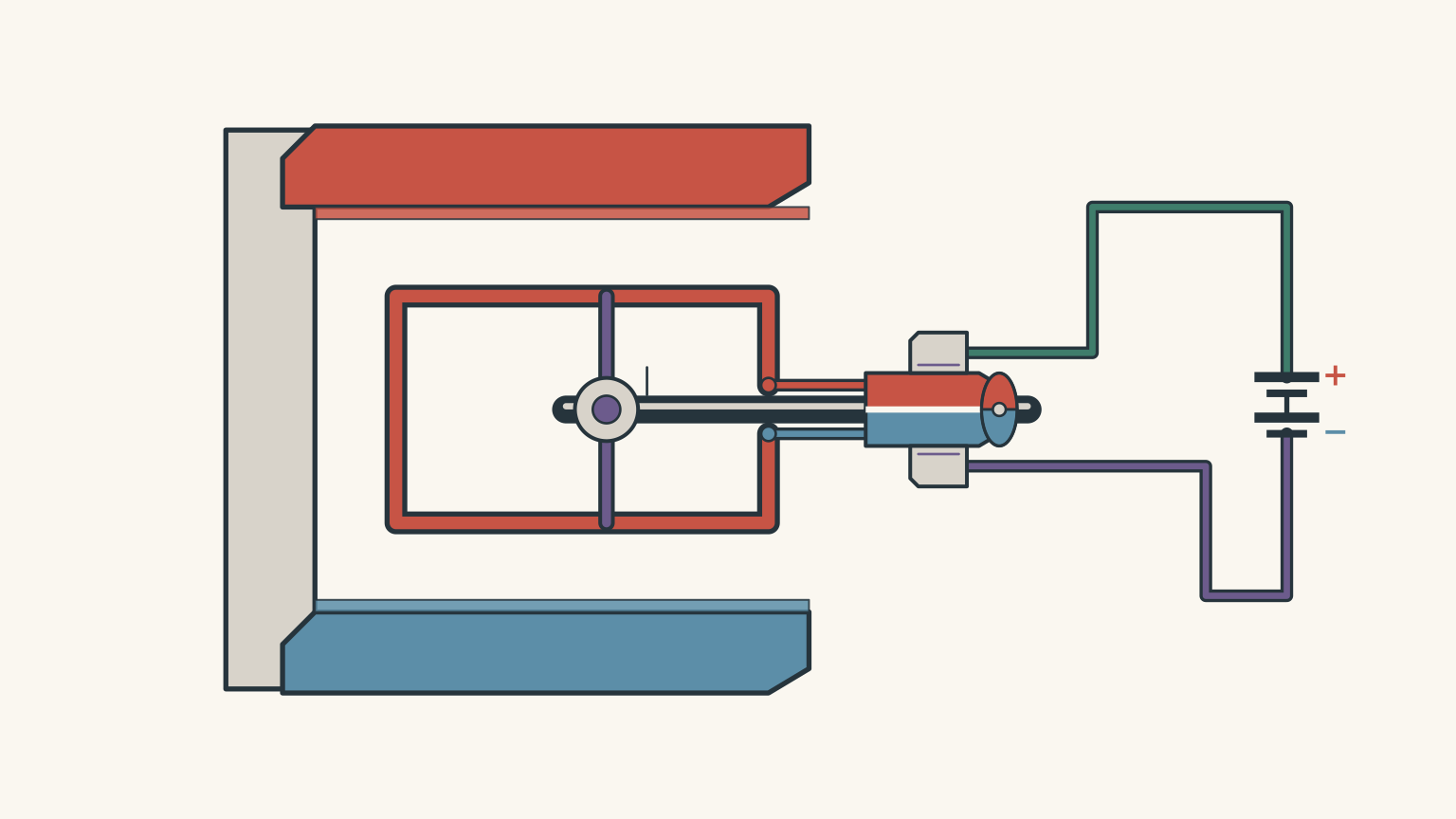
(a) State the function of each of the following components:
- Brushes.
- Split-ring commutator.
(2 marks)
(b) Explain how the split-ring commutator allows the coil to continue rotating in the same direction. (3 marks)
(c) A student claims that the split-ring commutator reverses the direction of rotation of the motor every half-turn.
Assess this claim. (1 mark)
Question 3 (8 marks)
A simple brushed DC motor is connected to an 18.0 V DC supply. Its armature has a resistance of 3.0 Ω.
During steady operation, the back emf generated by the motor is 12.0 V.
Assume that:
- The voltage drop across the brushes is negligible.
- Mechanical energy losses are negligible.
- The armature resistance remains constant.
Let:
- \(V_s\) = supply voltage, in volts.
- \(E_b\) = back emf, in volts.
- \(I\) = armature current, in amperes.
- \(R\) = armature resistance, in ohms.
Use:
\[ V_s=E_b+IR \]
For the power calculations, use:
\[ P_{\mathrm{in}}=V_sI \]
\[ P_{\mathrm{heat}}=I^2R \]
For this idealised motor:
\[ P_{\mathrm{mech}}=E_bI \]
(a) Calculate the armature current during steady operation. (2 marks)
(b) Calculate:
(i) The electrical power supplied to the motor.
(ii) The rate of electrical energy converted into thermal energy in the armature.
(iii) The rate of electrical energy converted into mechanical energy.
(3 marks)
(c) Explain how back emf is produced in a DC motor. In your answer, explain:
- Why its direction opposes the supply voltage.
- How its magnitude changes as the motor accelerates from rest.
- How this affects the current flowing through the armature.
(3 marks)
Question 4 (5 marks)
A DC motor operates from a constant 12.0 V supply. Its armature resistance is 1.5 Ω.
Under its initial mechanical load, the motor operates at a steady speed and produces a back emf of 9.0 V.
An additional mechanical load is then applied. The motor eventually settles at a lower rotational speed, where its back emf is 6.0 V.
Assume the supply voltage and armature resistance remain constant.
(a) Calculate the armature current:
(i) Before the additional load is applied.
(ii) After the motor reaches its new steady operating speed.
(2 marks)
(b) Explain the sequence of changes that occurs when the additional mechanical load is applied.
Your answer should link rotational speed, back emf, armature current, and torque. (3 marks)
Question 5 (7 marks)
A brushless DC motor has three stationary stator windings, labelled A, B, and C, surrounding a permanent-magnet rotor.
A DC supply provides electrical energy to an electronic controller. During each commutation step, the controller sends current through two stator phases while temporarily leaving the third phase unpowered.
In this particular motor arrangement, the controller estimates the rotor’s position by detecting the emf induced in the unpowered winding.
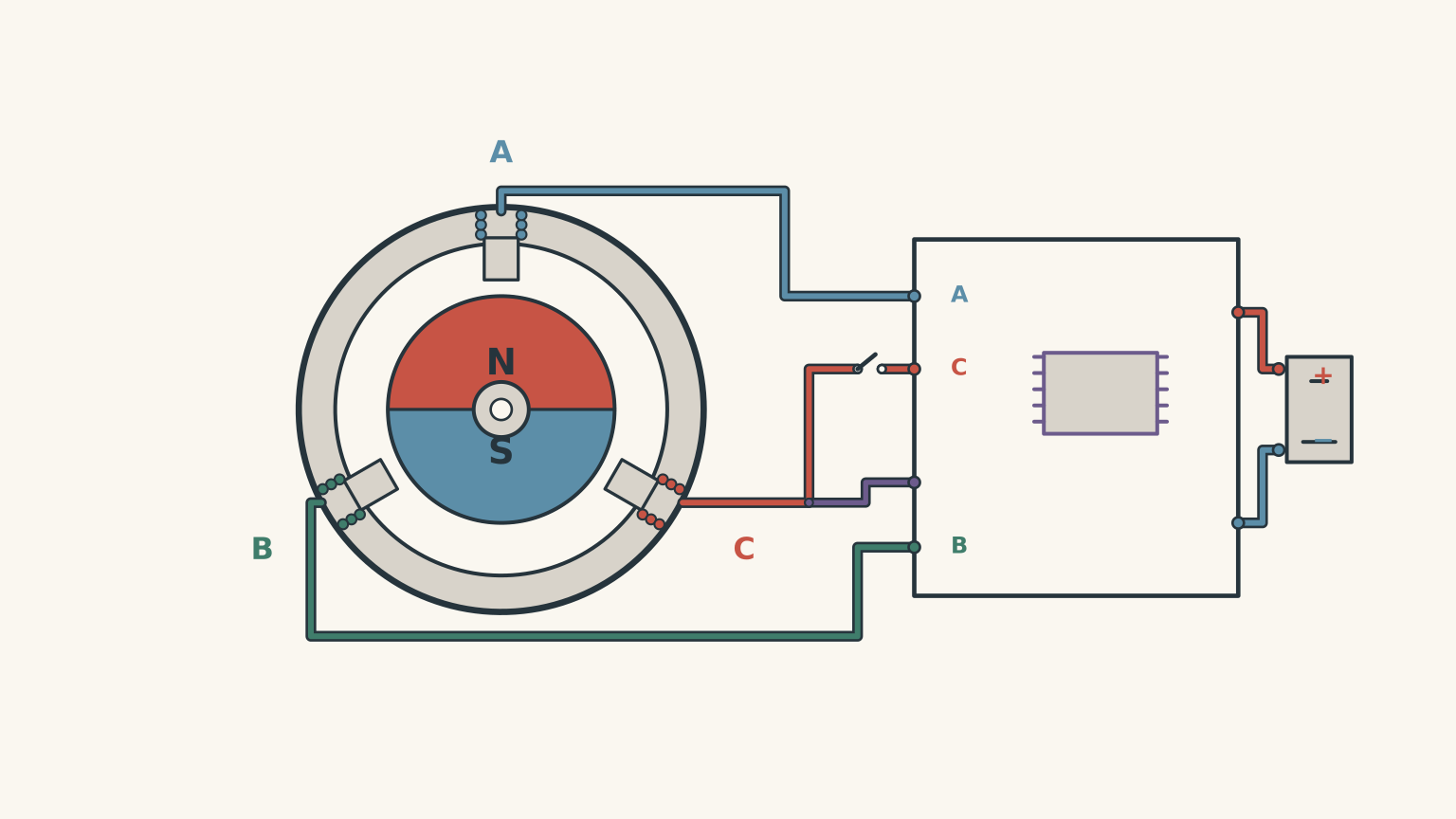
(a) Explain how sequentially energising the stator windings produces torque on the permanent-magnet rotor. (3 marks)
(b) Explain how electromagnetic induction in the temporarily unpowered winding helps the controller maintain continuous rotation. (2 marks)
(c) Compare the brushless DC motor in this question with the squirrel-cage AC induction motor from Question 1.
Your answer must identify:
- One difference in rotor construction.
- One difference in how torque is produced. (2 marks)
03Worked solutions and marking guide
Solution 1
(a) Rotating magnetic field (2 marks)
The three stator windings are supplied with alternating currents that are out of phase with one another.
Because the windings are arranged at different positions around the stator, their individual magnetic fields combine to produce a resultant magnetic field that continuously changes direction around the motor.
This creates a rotating magnetic field.
Marking guide:
- 1 mark for identifying that the three AC currents are phase-shifted and produce changing magnetic fields.
- 1 mark for explaining that their combined magnetic field rotates around the stator.
(b) Induced rotor currents and torque (3 marks)
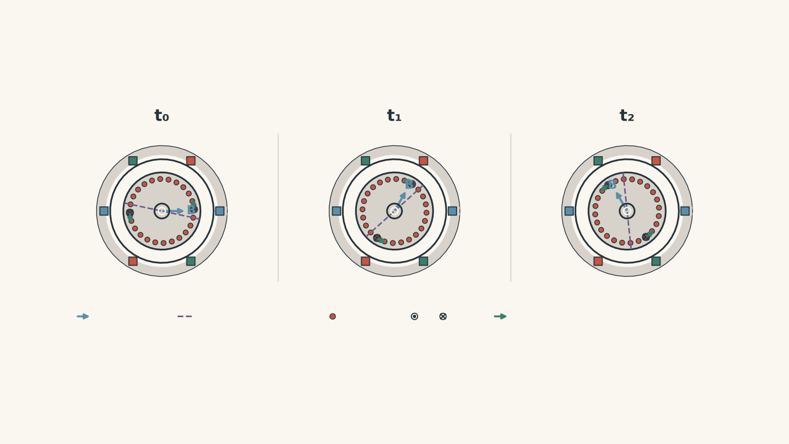
The rotating magnetic field moves relative to the conducting bars of the rotor.
This causes the magnetic flux through the rotor conductors to change, inducing an emf through electromagnetic induction.
The rotor bars and end rings form closed conducting paths. Therefore, the induced emf produces currents in the rotor.
These current-carrying conductors are now in the stator’s magnetic field. The motor effect produces forces on them, and the combined forces generate a torque that causes the rotor to turn.
Marking guide:
- 1 mark for explaining that relative motion between the rotating field and rotor conductors changes magnetic flux and induces an emf.
- 1 mark for explaining that the closed rotor circuits allow induced currents to flow.
- 1 mark for explaining that the interaction between the induced currents and magnetic field produces forces and a net torque.
(c) Rotor reaches the field’s speed (1 mark)
If the rotor reaches exactly the same angular speed as the rotating magnetic field, there is no relative motion between the field and the rotor conductors.
Consequently, there is no changing magnetic flux through the rotor, so no emf or induced rotor current is produced.
Without the induced rotor current, the motor cannot produce the torque required to maintain that speed.
Marking guide:
- 1 mark for identifying that zero relative motion means no induced rotor current and therefore no electromagnetic torque.
Solution 2
(a) Functions of the components (2 marks)
Brushes are stationary electrical contacts that transfer current from the external DC supply to the rotating commutator.
The split-ring commutator reverses the direction of current through the rotor coil every half-turn.
Marking guide:
- 1 mark for correctly describing the function of the brushes.
- 1 mark for correctly describing the function of the split-ring commutator.
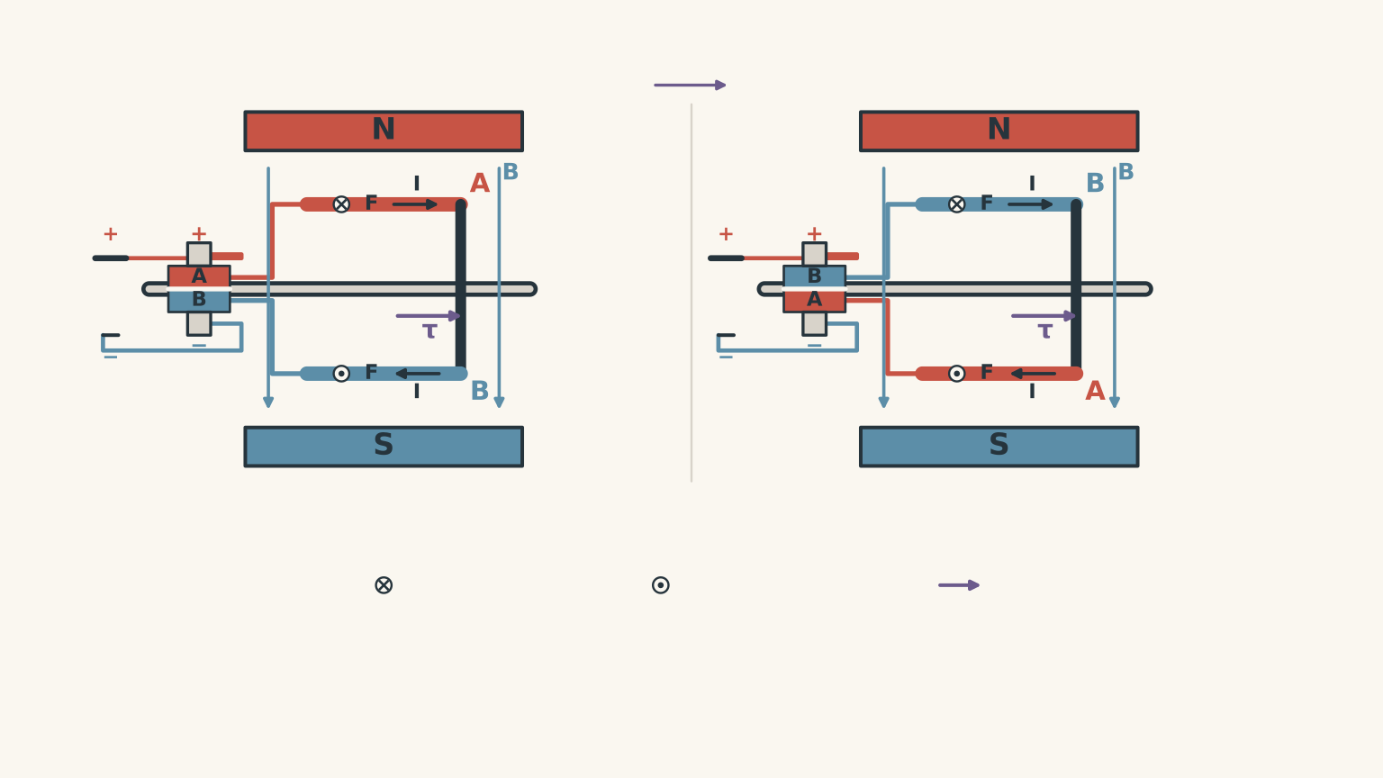
(b) Maintaining continuous rotation (3 marks)
A current-carrying conductor in a magnetic field experiences a force due to the motor effect.
In a rectangular coil, the two opposite sides experience forces in opposite directions. These forces form a couple, producing a torque that rotates the coil.
As the coil completes half a revolution, its two sides exchange positions relative to the magnetic poles. If the current remained unchanged, the torque would act in the opposite rotational direction.
The split-ring commutator prevents this from happening.
It reverses the current through the coil every half-turn. This also reverses the forces acting on the two sides of the coil at the correct time, so the torque continues acting in the same rotational direction.
Marking guide:
- 1 mark for explaining that the current-carrying coil experiences opposing forces that produce torque.
- 1 mark for identifying that the coil sides exchange positions relative to the magnetic field after half a revolution.
- 1 mark for explaining that the commutator reverses the current, maintaining torque in the same rotational direction.
(c) Assessing the student’s claim (1 mark)
The claim is incorrect.
The commutator reverses the direction of current through the coil, not the direction of rotation of the shaft.
Its purpose is to maintain torque in the same rotational direction so the motor can continue spinning.
Marking guide:
- 1 mark for identifying that the claim is incorrect and distinguishing reversal of current from reversal of shaft rotation.
Solution 3
(a) Calculating armature current (2 marks)
The supply voltage is shared between the back emf and the voltage drop across the armature resistance.
Therefore:
\[ V_s=E_b+IR \]
Rearranging:
\[ I=\frac{V_s-E_b}{R} \]
Substitute the given values:
\[ I=\frac{18.0-12.0}{3.0} \]
\[ \boxed{I=2.0\text{ A}} \]
The armature current is 2.0 A.
Marking guide:
- 1 mark for correctly rearranging and substituting into the voltage relationship.
- 1 mark for the correct answer, including units.
(b) Calculating power and energy transformations (3 marks)
(i) Electrical input power
Use:
\[ P_{\mathrm{in}}=V_sI \]
Substitute:
\[ P_{\mathrm{in}}=18.0\times2.0 \]
\[ \boxed{P_{\mathrm{in}}=36\text{ W}} \]
(ii) Thermal power loss
The armature resistance causes electrical energy to be converted into thermal energy.
Use:
\[ P_{\mathrm{heat}}=I^2R \]
Substitute:
\[ P_{\mathrm{heat}}=(2.0)^2\times3.0 \]
\[ \boxed{P_{\mathrm{heat}}=12\text{ W}} \]
(iii) Mechanical power conversion
For the idealised motor:
\[ P_{\mathrm{mech}}=E_bI \]
Substitute:
\[ P_{\mathrm{mech}}=12.0\times2.0 \]
\[ \boxed{P_{\mathrm{mech}}=24\text{ W}} \]
The energy balance is:
\[ P_{\mathrm{in}}= P_{\mathrm{heat}}+P_{\mathrm{mech}} \]
\[ 36=12+24 \]
This confirms that the electrical input power is accounted for by thermal and mechanical energy transfers.
Marking guide:
- 1 mark for correctly calculating the electrical input power.
- 1 mark for correctly calculating the thermal power loss.
- 1 mark for correctly calculating the mechanical power conversion and obtaining a consistent energy balance.
(c) Origin and effects of back emf (3 marks)
Back emf is produced through electromagnetic induction.
As the armature rotates inside the motor’s magnetic field, its conductors move through the field. This causes a change in magnetic flux linkage and induces an emf in the armature.
According to Lenz’s law, the induced emf acts in a direction that opposes the change producing it. In a DC motor, this means that the back emf opposes the applied supply voltage.
When the motor first starts, its rotational speed is zero. Therefore, there is initially no back emf.
As the motor accelerates, its conductors cut through the magnetic field more rapidly. The rate of change of magnetic flux increases, so the magnitude of the back emf increases.
Since the supply voltage remains constant, a larger back emf leaves a smaller voltage across the armature resistance:
\[ I=\frac{V_s-E_b}{R} \]
Therefore, the armature current decreases as the motor speeds up.
This is an important self-regulating feature of a DC motor. Back emf prevents the motor from continuing to draw its large starting current once it reaches its normal operating speed.
Marking guide:
- 1 mark for explaining that rotation in a magnetic field induces an emf in the armature.
- 1 mark for identifying that the induced emf opposes the supply voltage, consistent with Lenz’s law.
- 1 mark for explaining that increasing rotational speed increases back emf and reduces armature current.
Solution 4
(a) Calculating armature current (2 marks)
The supply voltage and armature resistance remain constant.
Use:
\[ I=\frac{V_s-E_b}{R} \]
(i) Before the additional load
The back emf is 9.0 V.
\[ I=\frac{12.0-9.0}{1.5} \]
\[ \boxed{I=2.0\text{ A}} \]
(ii) After the additional load
The back emf is 6.0 V.
\[ I=\frac{12.0-6.0}{1.5} \]
\[ \boxed{I=4.0\text{ A}} \]
The armature current increases from 2.0 A to 4.0 A.
Marking guide:
- 1 mark for the correct initial current of 2.0 A.
- 1 mark for the correct final current of 4.0 A.
(b) Effect of increased mechanical load (3 marks)
When the additional mechanical load is applied, it creates a greater opposing torque.
Initially, the motor slows down because its existing torque is insufficient to maintain its original speed against the increased load.
As the motor slows, the rate at which its armature conductors cut through the magnetic field decreases. This reduces the back emf.
The supply voltage remains constant, so the reduction in back emf increases the voltage across the armature resistance.
As a result, the armature current increases.
A larger current produces a greater motor effect and therefore a greater torque.
The motor can then accelerate towards a new steady operating condition, where the motor’s torque balances the increased mechanical load. It operates at a lower speed than before.
The complete sequence is:
\[ \text{Increased load} \]
\[ \Downarrow \]
\[ \text{Rotational speed decreases} \]
\[ \Downarrow \]
\[ \text{Back emf decreases} \]
\[ \Downarrow \]
\[ \text{Armature current increases} \]
\[ \Downarrow \]
\[ \text{Motor torque increases} \]
Marking guide:
- 1 mark for explaining that increased mechanical load initially reduces rotational speed.
- 1 mark for linking reduced speed to reduced back emf and increased current.
- 1 mark for explaining that increased current produces greater torque, allowing the motor to balance the increased load.
Solution 5
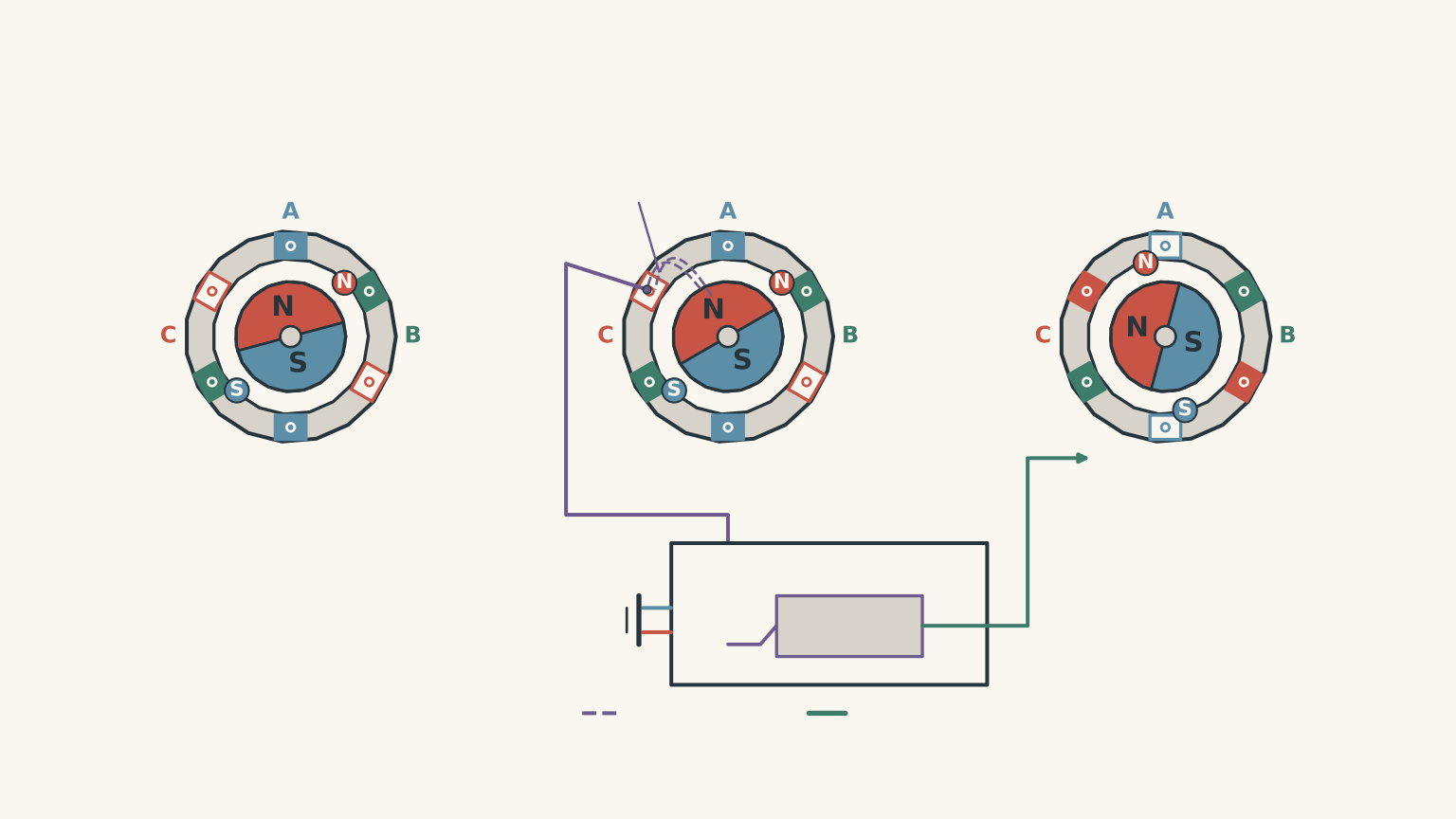
(a) Torque production in a brushless DC motor (3 marks)
A brushless DC motor uses stationary stator windings and a rotating permanent-magnet rotor.
When current flows through a stator winding, it creates an electromagnet. The direction of current determines the polarity of that electromagnet.
The electronic controller switches current through the stator phases in a particular sequence.
This causes the magnetic field produced by the stator to move around the motor.
The permanent-magnet rotor experiences attraction and repulsion from the stator’s magnetic poles. These magnetic interactions produce forces that generate torque about the rotor’s central axis.
As the controller continues switching the stator windings, the rotor follows the moving magnetic field and continues rotating.
Unlike a brushed DC motor, a brushless DC motor does not need physical brushes or a split-ring commutator to switch current through a rotating coil. The switching is performed electronically.
Marking guide:
- 1 mark for explaining that current in the stator windings creates magnetic poles.
- 1 mark for explaining that sequential switching moves the stator’s magnetic field.
- 1 mark for explaining that the interaction between the stator field and permanent-magnet rotor produces torque and rotation.
(b) Electromagnetic induction and continuous rotation (2 marks)
As the permanent-magnet rotor rotates, its magnetic field moves relative to the temporarily unpowered stator winding.
This changes the magnetic flux through that winding.
According to Faraday’s law of electromagnetic induction, the changing magnetic flux induces an emf in the winding.
The electronic controller detects this induced emf and uses its changing polarity or zero-crossing point to estimate the rotor’s position.
It can then determine when to switch current through the stator phases to maintain the rotating magnetic field and produce continuous torque.
An important distinction is that the induced emf in the unpowered winding is used as a position signal. It does not directly provide the mechanical turning force. The torque is produced by the magnetic interaction between the energised stator windings and the permanent-magnet rotor.
Marking guide:
- 1 mark for explaining that the moving rotor’s magnetic field changes the flux through the unpowered winding, inducing an emf.
- 1 mark for explaining that the controller uses the induced emf to estimate rotor position and time the next commutation step.
For this particular sensorless arrangement, the induced voltage provides the feedback needed to coordinate electronic commutation.【turn188100view0】
(c) Comparing brushless DC and AC induction motors (2 marks)
The two motors both use magnetic fields to produce rotational motion, but their rotor construction and torque-production mechanisms are different.
| Feature | Brushless DC motor | AC induction motor |
|---|---|---|
| Rotor construction | Permanent magnets | Conducting rotor bars joined by end rings |
| Stator supply | DC supply switched electronically through the stator phases | Three-phase AC supply |
| Rotor current | Rotor currents are not required for torque production in the permanent-magnet arrangement | Currents are induced in the conducting rotor |
| Torque production | Magnetic interaction between the permanent-magnet rotor and the electronically controlled stator field | Motor effect on the induced rotor currents in the rotating stator magnetic field |
In the brushless DC motor, the permanent-magnet rotor follows the magnetic field created by the electronically switched stator windings.
In the AC induction motor, the rotating stator magnetic field induces currents in the conducting rotor. These currents interact with the magnetic field to produce torque.
Therefore, although both motors use rotating magnetic fields, they do not rely on the same mechanism to produce torque.
Marking guide:
- 1 mark for identifying the difference between the permanent-magnet BLDC rotor and the conducting squirrel-cage induction rotor.
- 1 mark for distinguishing electronically controlled magnetic interaction from torque produced through induced rotor currents.
Total: 32 marks
End of practice paper.