
Diffraction of Light: Slit Width, Wavelength and HSC Physics
Understand why light spreads through narrow openings, how slit width and wavelength affect diffraction, and how to analyse diffraction patterns.
Shine a laser through a wide opening and the light mostly keeps travelling forwards. Now make the opening narrower. What should happen?
A ray model suggests a narrower opening should give you a narrower strip of light. Instead, once the opening becomes small enough, the light spreads out more.
That is diffraction. The strange part is worth remembering: making an opening narrower can make the transmitted light spread wider.
01Why does light spread after a narrow opening?
Start by picturing a flat wavefront approaching a slit.
If the slit is very wide compared with the wavelength, most of the wave continues forwards. There is some spreading near the edges, but the overall beam still looks fairly straight.
Now shrink the slit until its width is much closer to the wavelength. The emerging wave spreads through a much larger range of directions.
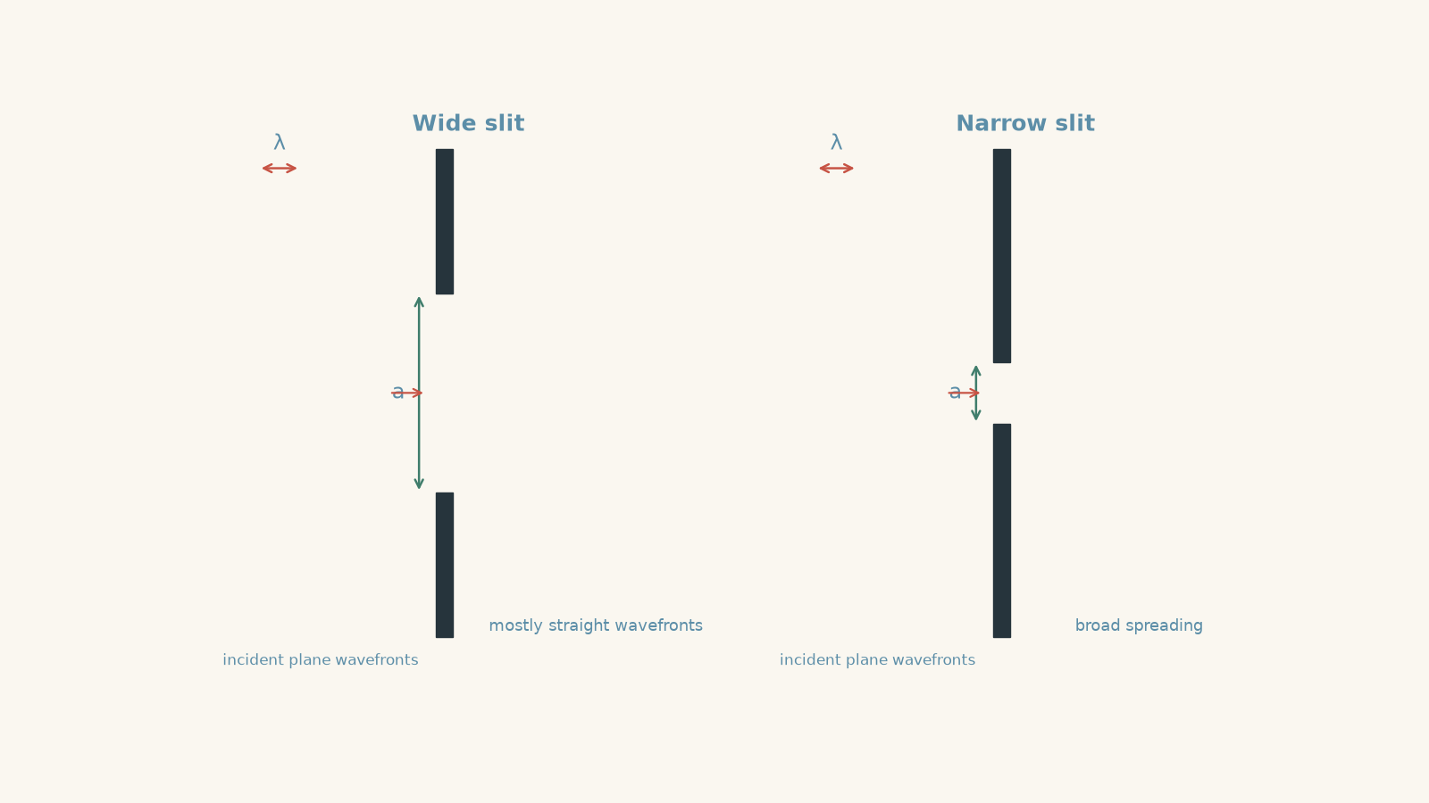
A useful first model comes from Huygens’ principle. Imagine every point across the opening receiving the same group-chat message: “Start a new wave now.” Each point acts like a source of a small secondary wavelet.
Those wavelets overlap. In a wide opening, contributions travelling sideways tend to cancel much more strongly, leaving most of the wave travelling forwards. In a narrow opening, there is less cancellation of those off-axis contributions, so significant light survives over a wider range of directions.
The analogy breaks in one important place: there are not literally hundreds of tiny light sources sitting inside the slit. Huygens’ construction is a way of predicting how an existing wavefront propagates.
This also fixes a common but misleading explanation. Light does not diffract because photons hit the edges and ricochet sideways. The whole transmitted wavefront contributes to the diffraction pattern.
02The comparison that matters: wavelength versus opening size
The two important quantities are:
- \(\lambda\), the wavelength of the light, measured in metres
- \(a\), the width of the opening, measured in metres
A useful comparison is the dimensionless ratio
\[
\frac{\lambda}{a}
\]
This is not a separate “diffraction formula” that gives an exact amount of bending. It is a way to compare situations.
| Relative size | What you expect |
|---|---|
| \(a \gg \lambda\) | Very little noticeable spreading |
| \(a\) only moderately larger than \(\lambda\) | Diffraction becomes noticeable |
| \(a\) comparable with \(\lambda\) | Strong spreading |
| \(a\) smaller than \(\lambda\) | Very strong wave effects, although transmission through the tiny opening can also become weak |
So there is no magic switch where diffraction suddenly begins at \(a=\lambda\). Diffraction occurs for any finite opening. It is simply much harder to notice when the opening is enormous compared with the wavelength.
Visible light has wavelengths of roughly a few hundred nanometres. A doorway is about a metre wide, so the doorway is millions of wavelengths across. That is why visible light does not noticeably fan around an ordinary doorway.
Sound is different. A 500 Hz sound travelling at about \(340\ \text{m s}^{-1}\) has wavelength
\[
\lambda=\frac{v}{f}
=\frac{340}{500}
=0.68\ \text{m}
\]
where \(v\) is the wave speed and \(f\) is the frequency.
A \(0.68\ \text{m}\) wavelength is comparable with a doorway. That is why you can hear someone speaking from around an open doorway even when you cannot see them. The same wave behaviour is occurring; the relative sizes are just very different.
Worked example: Which colour spreads more?
Red light of wavelength \(650\ \text{nm}\) and blue light of wavelength \(450\ \text{nm}\) are sent separately through the same \(0.10\ \text{mm}\) slit. Which produces more noticeable diffraction?
Step 1
Both colours pass through the same slit, so \(a\) is constant. The light with the larger wavelength therefore has the larger \(\lambda/a\) ratio.
Step 2
For red light,
\[
\lambda_{\text{red}}=650\times10^{-9}\ \text{m}
\]
For blue light,
\[
\lambda_{\text{blue}}=450\times10^{-9}\ \text{m}
\]
The slit width is
\[
a=0.10\ \text{mm}=1.0\times10^{-4}\ \text{m}
\]
Step 3
\[
\frac{\lambda_{\text{red}}}{a}
=
\frac{650\times10^{-9}}{1.0\times10^{-4}}
=
6.5\times10^{-3}
\]
and
\[
\frac{\lambda_{\text{blue}}}{a}
=
\frac{450\times10^{-9}}{1.0\times10^{-4}}
=
4.5\times10^{-3}
\]
Step 4
The red light has the larger wavelength-to-slit-width ratio, so it produces the greater angular spread.
The tempting shortcut is “red bends more”. Be more precise. Nothing here is causing red light to undergo refraction. It diffracts more because its wavelength is larger relative to the opening.
03Why narrowing the slit increases diffraction
Suppose you keep the wavelength fixed and halve the slit width.
Predict what happens to \(\lambda/a\).
Because \(a\) becomes smaller, \(\lambda/a\) becomes larger. The wave therefore spreads through a greater range of angles.
This feels backwards if you are thinking entirely in terms of rays or particles. A smaller hole seems as though it should restrict the beam more tightly. That prediction ignores the wave nature of the light.
There is another effect, though: a narrower opening lets less light through. So two things happen together:
- the transmitted pattern becomes more spread out, and
- the total transmitted light generally decreases.
“More diffraction” does not mean “more light”.
Worked example: From frequency to a diffraction prediction
Monochromatic light has a frequency of \(5.0\times10^{14}\ \text{Hz}\). It is sent first through a \(0.30\ \text{mm}\) slit and then through a \(0.030\ \text{mm}\) slit. Predict which slit produces the more pronounced diffraction.
Take the speed of light in air as approximately \(3.0\times10^8\ \text{m s}^{-1}\).
Step 1
For an electromagnetic wave,
\[
c=f\lambda
\]
where \(c\) is the speed of light, \(f\) is frequency, and \(\lambda\) is wavelength.
Rearranging,
\[
\lambda=\frac{c}{f}
=
\frac{3.0\times10^8}{5.0\times10^{14}}
=
6.0\times10^{-7}\ \text{m}
\]
So the wavelength is \(600\ \text{nm}\).
Step 2
For \(a=0.30\ \text{mm}=3.0\times10^{-4}\ \text{m}\),
\[
\frac{\lambda}{a}
=
\frac{6.0\times10^{-7}}{3.0\times10^{-4}}
=
2.0\times10^{-3}
\]
Step 3
For \(a=0.030\ \text{mm}=3.0\times10^{-5}\ \text{m}\),
\[
\frac{\lambda}{a}
=
\frac{6.0\times10^{-7}}{3.0\times10^{-5}}
=
2.0\times10^{-2}
\]
Step 4
The narrower slit gives a wavelength-to-width ratio ten times larger. It will therefore produce much more pronounced spreading.
Notice what we have not claimed. We have not used \(\lambda/a\) as an exact equation for the measured pattern width. We have used it to make a reliable qualitative comparison.
04What appears on the screen?
A single slit does not normally produce a uniformly illuminated fan of light.
Instead, different parts of the wave passing through the opening interfere with one another. The screen shows a broad, bright central region with darker regions and weaker bright bands on either side.
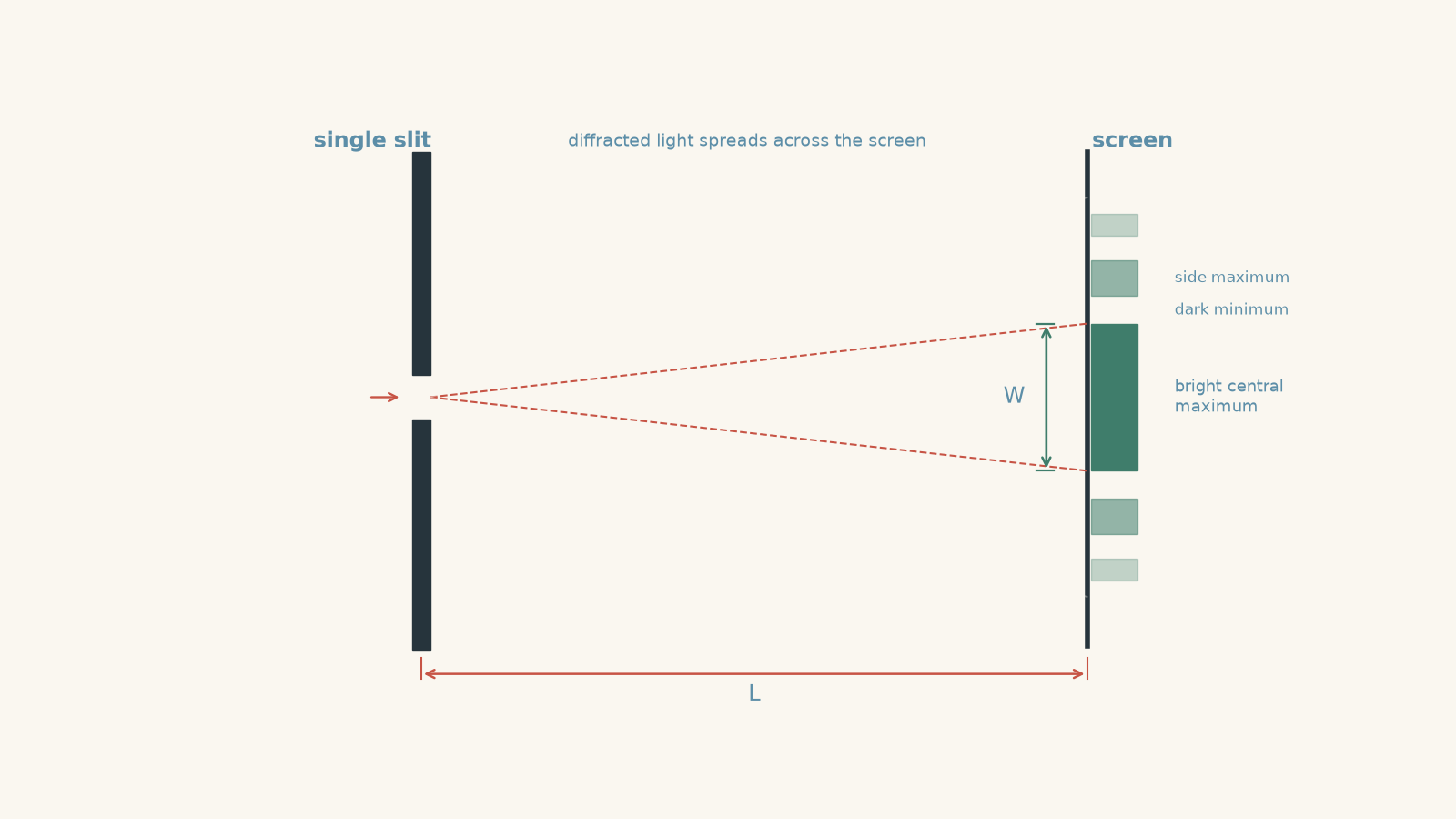
That pattern is an important clue about what diffraction really is. It is not merely “light bending at an edge”. It comes from the superposition of waves transmitted through different parts of the aperture.
As the slit becomes narrower, the diffraction pattern spreads over a larger angle. The bright central region becomes broader on a screen placed at the same distance.
05How to investigate diffraction properly
A simple investigation can test how slit width affects the spreading of monochromatic light.
Use a low-power classroom laser, a set of narrow slits or an adjustable slit, and a screen. Never look into the laser beam or direct it towards another person’s eyes.
Place the screen a fixed distance \(L\) behind the slit. Begin with a relatively wide slit, observe the pattern, and then progressively decrease the slit width.
Before doing it, make the prediction: if the wave model is correct, should the central region become wider or narrower?
It should become wider. Narrowing the opening increases the wavelength-to-opening-width ratio, so the angular spread increases.
Variables
A sensible investigation would use:
| Variable | Choice |
|---|---|
| Independent variable | Slit width \(a\) |
| Dependent variable | Width or angular spread of the diffraction pattern |
| Controlled variables | Wavelength, screen distance, laser alignment, measurement method, and ambient conditions |
Keeping the wavelength fixed matters. Otherwise, changing colour and changing slit width at the same time would make it difficult to tell which change caused the new pattern.
Keeping the screen distance fixed also matters.
Suppose the diffraction angle stays exactly the same but you move the screen twice as far away. The pattern on the screen becomes roughly twice as wide even though the diffraction itself has not changed.
That means screen width alone is not always a fair measure of diffraction.
If \(W\) is the width of the central bright region and \(L\) is the distance from slit to screen, the half-angle \(\theta\) can be found geometrically from
\[
\tan\theta=\frac{W/2}{L}
\]
or
\[
\theta=\tan^{-1}\left(\frac{W}{2L}\right)
\]
This lets you compare angular spreading even when \(L\) is not identical.
What should the investigation show?
As \(a\) decreases while \(\lambda\) remains constant:
- the angular spread increases,
- the central bright region becomes wider at a fixed screen distance,
- the side features spread further apart, and
- less total light generally passes through the opening.
Repeated measurements are useful because deciding exactly where a bright region ends can be difficult. A darker room, a fixed screen position, careful alignment, and repeated measurements improve the quality of the data.
06Diffraction is not refraction
These two words both involve light changing direction, so they are easy to mix up.
| Diffraction | Refraction |
|---|---|
| Occurs when a wave passes an obstacle or restricted opening | Occurs when a wave enters a region where its speed changes |
| Depends strongly on wavelength relative to obstacle or opening size | Depends on wave speed in the two media |
| Can occur while the light remains in the same medium | Requires a change in propagation conditions between media |
| Produces spreading and, for an aperture, an interference pattern | Usually produces a change in the direction of a transmitted ray |
Passing through a slit does not automatically change the speed or frequency of the light. The spreading is therefore not explained by refraction.
07The misconceptions worth catching
“Diffraction only happens when the opening equals the wavelength”
No. Diffraction does not switch on at a threshold.
It occurs whenever a wave is restricted by an opening or obstacle. The effect becomes much more noticeable as the opening size approaches the wavelength.
“A narrower opening gives a narrower beam”
That is a reasonable prediction from a simple ray model, but it fails for sufficiently narrow openings.
A smaller \(a\) gives a larger \(\lambda/a\), so the transmitted wave spreads more.
“The light hits the edges and bounces sideways”
The edges are not tiny mirrors.
The aperture restricts the original wavefront. The remaining parts of that wavefront contribute waves that superpose and produce the diffraction pattern.
“Longer wavelengths always diffract more”
Only if the relevant opening size is the same.
A shorter wavelength passing through a much narrower slit can diffract more than a longer wavelength passing through a wider slit. You must compare \(\lambda\) with \(a\), not \(\lambda\) by itself.
“A wider pattern on the screen always means more diffraction”
Not necessarily.
A pattern also gets physically wider when you move the screen further away. Compare angles, or keep the screen distance fixed.
08Questions and solutions
Question 1
Red light with wavelength \(650\ \text{nm}\) and violet light with wavelength \(405\ \text{nm}\) pass separately through the same \(0.080\ \text{mm}\) slit.
Which light produces the greater diffraction? Support your answer by comparing \(\lambda/a\).
Solution 1
The red light produces the greater diffraction because its wavelength is larger relative to the same slit width.
Convert the slit width:
\[
a=0.080\ \text{mm}=8.0\times10^{-5}\ \text{m}
\]
For red light,
\[
\frac{\lambda}{a}
=
\frac{650\times10^{-9}}{8.0\times10^{-5}}
=
8.1\times10^{-3}
\]
For violet light,
\[
\frac{\lambda}{a}
=
\frac{405\times10^{-9}}{8.0\times10^{-5}}
=
5.1\times10^{-3}
\]
The red light has the larger ratio, so its diffraction pattern has the greater angular spread.
A tempting explanation is that red light “bends more easily”. That hides the actual physics. The important constraint is the wavelength relative to the opening width.
Question 2
Two experiments are performed.
| Trial | Wavelength | Slit width |
|---|---|---|
| A | \(650\ \text{nm}\) | \(0.20\ \text{mm}\) |
| B | \(450\ \text{nm}\) | \(0.10\ \text{mm}\) |
A student argues that Trial A must show more diffraction because red light has the longer wavelength.
Determine which trial should actually show greater spreading, and explain the flaw in the student’s argument.
Solution 2
Trial B should show greater spreading, despite using the shorter wavelength.
For Trial A,
\[
\frac{\lambda_A}{a_A}
=
\frac{650\times10^{-9}}{0.20\times10^{-3}}
=
3.25\times10^{-3}
\]
For Trial B,
\[
\frac{\lambda_B}{a_B}
=
\frac{450\times10^{-9}}{0.10\times10^{-3}}
=
4.50\times10^{-3}
\]
Therefore,
\[
\frac{\lambda_B}{a_B}>
\frac{\lambda_A}{a_A}
\]
so Trial B produces the greater angular spread.
The student’s reasoning would work only if slit width were held constant. Here, two things change at once. Trial B has a shorter wavelength, which tends to reduce diffraction, but it also has a much narrower slit, which tends to increase diffraction. The slit-width change wins.
This is why “longer wavelength means more diffraction” is an incomplete rule. The useful comparison is wavelength relative to the size of the opening.
Question 3
The same laser is used in two trials.
| Trial | Slit width \(a\) | Screen distance \(L\) | Measured central width \(W\) |
|---|---|---|---|
| 1 | \(0.20\ \text{mm}\) | \(1.00\ \text{m}\) | \(8.0\ \text{mm}\) |
| 2 | \(0.10\ \text{mm}\) | \(1.50\ \text{m}\) | \(24.0\ \text{mm}\) |
A student states, “The pattern became three times wider, so the diffraction angle became three times larger.”
Evaluate the statement. Calculate the half-angle of the central region in each trial, and identify how the experimental design could be improved.
Solution 3
The diffraction angle increased by about a factor of two, not three; the student’s comparison ignores the change in screen distance.
For Trial 1,
\[
\tan\theta_1=\frac{W_1/2}{L_1}
=
\frac{4.0\times10^{-3}}{1.00}
=
4.0\times10^{-3}
\]
Therefore,
\[
\theta_1=\tan^{-1}(4.0\times10^{-3})
\approx0.229^\circ
\]
For Trial 2,
\[
\tan\theta_2
=
\frac{12.0\times10^{-3}}{1.50}
=
8.0\times10^{-3}
\]
so
\[
\theta_2=\tan^{-1}(8.0\times10^{-3})
\approx0.458^\circ
\]
Thus,
\[
\frac{\theta_2}{\theta_1}
\approx
\frac{0.458}{0.229}
\approx2.0
\]
The second pattern is physically three times wider on the screen, but the screen is also \(1.5\) times farther from the slit. Both changes contribute to the measured width.
The experiment would be cleaner if \(L\) were kept constant while slit width was changed. If that is not possible, the student should compare calculated angular spreads rather than raw screen widths.
The tempting route is to treat \(W\) as a direct measure of diffraction. The missing constraint is geometry: the same angular spread produces a larger physical pattern on a more distant screen.
Question 4
A laser has wavelength \(660\ \text{nm}\) in air. A \(2.0\ \mu\text{m}\) slit and the observation screen are initially in air.
The entire region containing the slit and screen is then filled with water of refractive index \(1.33\). The physical slit width does not change.
Assume the frequency of the laser remains constant.
Predict how the diffraction changes in water. Calculate the wavelength in water and compare \(\lambda/a\) in the two cases.
A student argues that the diffraction must stay unchanged because the laser has the same frequency.
Solution 4
The diffraction becomes less pronounced in water because the wavelength becomes shorter while the physical slit width remains unchanged.
The frequency does remain constant when light enters water, but its speed decreases. Since
\[
v=f\lambda
\]
a lower wave speed at constant frequency means a shorter wavelength.
Using
\[
n=\frac{c}{v}
\]
the wavelength in a medium can be written as
\[
\lambda_{\text{water}}
=
\frac{\lambda_{\text{air}}}{n}
\]
Therefore,
\[
\lambda_{\text{water}}
=
\frac{660\ \text{nm}}{1.33}
\approx496\ \text{nm}
\]
The slit width is
\[
a=2.0\ \mu\text{m}=2000\ \text{nm}
\]
In air,
\[
\frac{\lambda_{\text{air}}}{a}
=
\frac{660}{2000}
=
0.330
\]
In water,
\[
\frac{\lambda_{\text{water}}}{a}
=
\frac{496}{2000}
=
0.248
\]
The smaller ratio in water means less angular spreading.
The student’s tempting argument focuses only on frequency. Frequency does stay constant, but diffraction depends on wavelength relative to the aperture size. Because the speed changes in water, the wavelength changes as well.
This is also a useful reminder that wavelength is not an unchangeable property of a light wave. Frequency is fixed by the source as light crosses a boundary, while wave speed and wavelength depend on the medium.
Question 5
A double-slit arrangement uses light of wavelength \(600\ \text{nm}\). The centres of the two slits are separated by
\[
d=0.30\ \text{mm}
\]
and each slit initially has width
\[
a=0.060\ \text{mm}.
\]
The width of each slit is then reduced to \(0.030\ \text{mm}\), while \(d\), the wavelength, and the screen position remain unchanged.
A student makes two predictions:
- The individual interference fringes will move farther apart because each slit now diffracts more.
- A larger number of interference fringes may be visible across the broadened region illuminated by the two slits.
Evaluate both predictions. Use the double-slit relationship
\[
d\sin\theta=m\lambda
\]
to check the position of the first-order interference maximum before and after the slit width is changed.
Solution 5
The first prediction is incorrect, but the second is correct: narrowing each slit broadens the diffraction envelope without changing the angular positions of the double-slit interference fringes.
For the first-order interference maximum, \(m=1\). The double-slit relationship is
\[
d\sin\theta=m\lambda
\]
where \(d\) is the centre-to-centre separation of the slits, \(\theta\) is the angle to the interference maximum, \(m\) is the interference order, and \(\lambda\) is the wavelength.
Substituting,
\[
(0.30\times10^{-3})\sin\theta
=
(1)(600\times10^{-9})
\]
so
\[
\sin\theta
=
\frac{600\times10^{-9}}{0.30\times10^{-3}}
=
2.0\times10^{-3}
\]
and therefore
\[
\theta
=
\sin^{-1}(2.0\times10^{-3})
\approx0.115^\circ
\]
After the individual slit widths are halved, neither \(d\) nor \(\lambda\) has changed. The calculation is therefore identical:
\[
\theta\approx0.115^\circ
\]
The first-order interference fringe stays at the same angle. The other interference orders also remain at the same angular positions.
So why does narrowing the individual slits still matter?
Each individual slit produces diffraction. Reducing \(a\) increases \(\lambda/a\), so the light emerging from each slit spreads over a wider range of angles. The two diffracted waves can therefore overlap over a broader angular region.
Within that broader region, the two waves still interfere according to their centre-to-centre separation \(d\). This can allow more interference fringes to be visible within the overall diffraction envelope, although the total transmitted intensity also decreases as the slits become narrower.
The tempting mistake is to treat slit width \(a\) and slit separation \(d\) as though they control the same feature.
They do different jobs:
- \(a\), the width of each slit, controls the broad diffraction envelope.
- \(d\), the separation between the slit centres, controls the positions and spacing of the double-slit interference fringes.
That distinction is the hinge. More diffraction does not automatically mean wider interference-fringe spacing.
09What diffraction lets you understand next
Diffraction explains why light from a narrow slit can reach places that a simple ray diagram says should remain dark. More importantly, it explains how light emerging from neighbouring slits can overlap.
Once those diffracted waves overlap, superposition decides whether they reinforce or cancel. That takes you directly into double-slit interference and diffraction gratings.
Keep the two length scales separate as you move on: the width of each opening controls how broadly each wave spreads, while the separation between openings controls how the overlapping waves interfere.