
Huygens’ Wave Model of Light: HSC Physics Explained
Learn how Huygens' wavefront construction explains refraction, diffraction, and the evidence that supports the wave behaviour of light.
A straight wavefront of light hits a glass surface at an angle. One side enters the glass first and slows down, while the other side is still moving faster through air. What should happen to the wavefront?
It pivots. The part that enters first falls behind, which changes the direction the light travels. Huygens’ wave model turns that simple idea into a geometric construction that explains refraction, and it gives us a way to think about diffraction and interference as well.
The important question is not just whether Huygens’ model can explain an observation. Particle models can explain some of the same observations. We want to know where the wave model makes a different prediction and which prediction the evidence supports.
01Start with a wavefront, not a ray
You’ve probably drawn light as a ray: a straight line with an arrow showing the direction of travel.
A ray is useful, but it hides the wave.
Imagine a series of crests moving across water. At one instant, you could draw a line through all the points that are at the same stage of their oscillation. For light, we use the same idea even though there isn’t a literal water surface moving up and down.
A wavefront is a line, or surface in three dimensions, joining points of the wave that have the same phase.
For a plane wave, the wavefronts look like parallel lines:
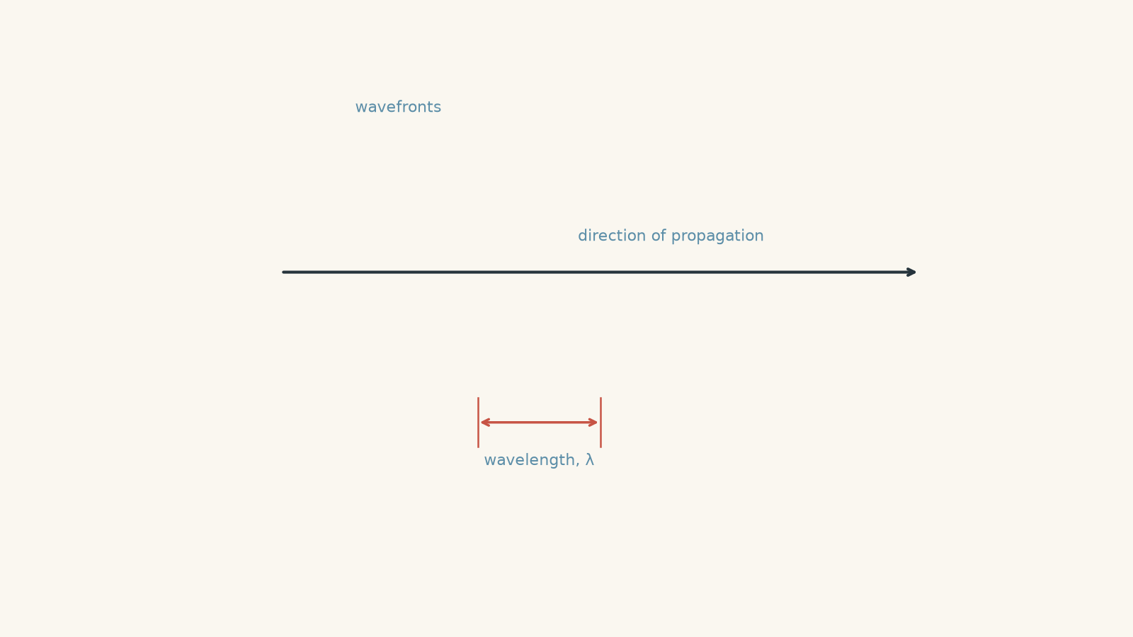
The relationship between the two pictures is:
| Idea | What it tells you |
|---|---|
| Wavefront | Where the wave has the same phase |
| Ray | Which direction the wave is travelling |
| Wavelength, \(\lambda\) | Perpendicular distance between equivalent neighbouring wavefronts |
| In an ordinary isotropic medium | Rays are perpendicular to wavefronts |
That last rule matters. If a wavefront rotates, the ray direction rotates with it.
02Huygens’ construction
Suppose you know where a wavefront is now and want to know where it will be a short time later.
Huygens’ idea is:
- Treat every point on the existing wavefront as a source of a small secondary wavelet.
- Let those wavelets spread for the same time interval, \(\Delta t\).
- Each wavelet travels a distance \(v\Delta t\), where \(v\) is the wave speed.
- Draw the new wavefront as the common tangent, or envelope, touching the forward edge of the secondary wavelets.
That tangent is the next position of the wavefront.
Think of a rumour spreading across a school oval. Everyone on the current “rumour front” starts passing the news onwards. A moment later, the new outer boundary reached by the rumour is the next front.
It’s useful, but the analogy breaks quickly. Light isn’t made from people passing messages, and Huygens’ little wavelets aren’t extra sources creating new energy from nowhere. They are a construction for working out how an existing wave propagates.
Why light travels straight in a uniform medium
Start with a straight wavefront in one uniform material.
After time \(\Delta t\), every secondary wavelet has the same radius:
\[ r=v\Delta t \]
Because every part travels at the same speed, the tangent to all those equal wavelets is another straight wavefront parallel to the first.
So the wavefront moves forward without rotating. The ray remains straight.
This is already useful: Huygens’ model does not say waves must visibly curve everywhere. In a uniform medium, a plane wave continues in a straight direction.
03Why a wave bends at a boundary
Now send the same plane wave from air into glass at an angle.
Before reading on, predict what happens to the wavefront if light travels more slowly in the glass. Does the part entering glass first get ahead, or fall behind?
It falls behind.
One side of the wavefront is already moving slowly through glass while the other side is still moving faster through air. The front therefore pivots.
It’s much like a row of supermarket trolleys rolling diagonally from smooth tiles onto thick carpet. The wheel that reaches the carpet first slows first, so the row turns. The trolley picture is only an analogy: light is not being mechanically dragged sideways by the glass.
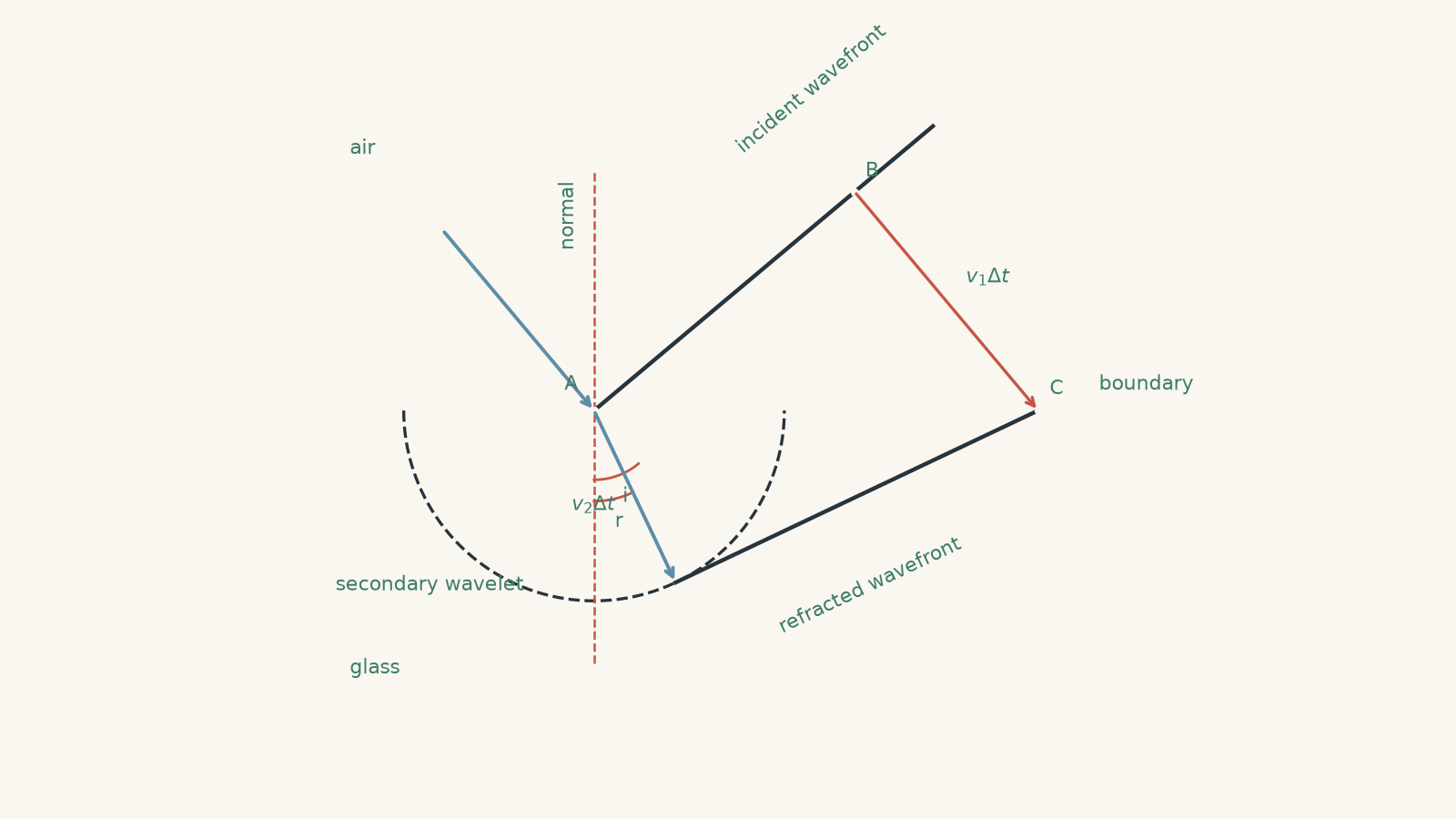
If the second medium is slower, its secondary wavelets have smaller radii in the same time. That difference in radius creates the rotation.
The ray, being perpendicular to the wavefront, bends towards the normal.
04Huygens’ construction gives Snell’s law
Now we can make that picture precise.
Let:
- \(v_1\) be the speed of light in medium 1,
- \(v_2\) be the speed in medium 2,
- \(i\) be the incident angle measured from the normal,
- \(r\) be the refracted angle measured from the normal, and
- \(\Delta t\) be a short time interval.
During \(\Delta t\), the part of the wave still in medium 1 travels
\[ v_1\Delta t \]
while the secondary wavelet already travelling through medium 2 grows to radius
\[ v_2\Delta t. \]
The geometry of the two right-angled triangles in the Huygens construction gives
\[ \frac{\sin i}{\sin r}=\frac{v_1}{v_2}. \]
Refractive index is defined by
\[ n=\frac{c}{v}, \]
where \(n\) is refractive index, \(c\) is the speed of light in vacuum, and \(v\) is the speed of light in the material.
Therefore,
\[ \frac{v_1}{v_2}=\frac{n_2}{n_1}, \]
so
\[ n_1\sin i=n_2\sin r. \]
That’s Snell’s law.
The equation isn’t a separate fact that Huygens’ model happens to agree with. It falls directly out of the wavefront construction.
05What happens to frequency and wavelength?
Slowing a wave creates another question. If its speed changes, what happens to \(f\) and \(\lambda\) in
\[ v=f\lambda? \]
A common prediction is that the frequency falls because the wave is moving more slowly.
It doesn’t.
For a stationary boundary, the frequency remains the same. The oscillations arriving at the boundary drive oscillations on the other side at the same rate. You don’t suddenly lose every fifth crest just because the material changes.
So:
- speed can change,
- wavelength can change,
- frequency remains constant.
Since \(v=f\lambda\), if \(f\) stays fixed and \(v\) decreases, \(\lambda\) must decrease too.
This gives
\[ \frac{\lambda_2}{\lambda_1}=\frac{v_2}{v_1}. \]
A slower medium therefore has more closely spaced wavefronts.
Worked example: Wavefront spacing inside glass
Light with wavelength \(540\text{ nm}\) in air enters glass normally. The glass has refractive index \(1.50\). Calculate the frequency of the light, its speed in the glass, and its wavelength in the glass. Describe what happens to the wavefronts.
Step 1
Using \(v=f\lambda\), and taking the speed in air as approximately \(c=3.00\times10^8\text{ m s}^{-1}\),
\[ f=\frac{v}{\lambda} =\frac{3.00\times10^8}{540\times10^{-9}} =5.56\times10^{14}\text{ Hz}. \]
Step 2
Using \(n=c/v\),
\[ v=\frac{c}{n} =\frac{3.00\times10^8}{1.50} =2.00\times10^8\text{ m s}^{-1}. \]
Step 3
\[ \lambda=\frac{v}{f} =\frac{2.00\times10^8}{5.56\times10^{14}} =3.60\times10^{-7}\text{ m} =360\text{ nm}. \]
Step 4
The light slows from approximately \(3.00\times10^8\text{ m s}^{-1}\) to \(2.00\times10^8\text{ m s}^{-1}\), while its frequency remains \(5.56\times10^{14}\text{ Hz}\). Its wavelength shrinks from \(540\text{ nm}\) to \(360\text{ nm}\).
Because the light arrives normally, there is no wavefront rotation and therefore no change of direction. The wavefronts simply become more closely spaced.
Worked example: Constructing a refracted direction
A plane light wave travels from air into a liquid with refractive index \(1.33\). Its incident angle is \(52.0^\circ\). Calculate the refracted angle. Then compare how far light travels through air and through the liquid in \(1.00\text{ ns}\).
Step 1
Take \(n_1=1.00\) for air and \(n_2=1.33\):
\[ n_1\sin i=n_2\sin r. \]
So
\[ \sin r =\frac{1.00\sin52.0^\circ}{1.33} =0.592, \]
giving
\[ r=36.3^\circ. \]
The ray bends towards the normal.
Step 2
\[ v=\frac{c}{n} =\frac{3.00\times10^8}{1.33} =2.26\times10^8\text{ m s}^{-1}. \]
Step 3
In air,
\[ d_{\text{air}} =(3.00\times10^8)(1.00\times10^{-9}) =0.300\text{ m}. \]
In the liquid,
\[ d_{\text{liquid}} =(2.26\times10^8)(1.00\times10^{-9}) =0.226\text{ m}. \]
Step 4
During the same time interval, the secondary wavelet in the liquid grows only \(0.226\text{ m}\), while the part of the wave remaining in air can travel \(0.300\text{ m}\).
That unequal progress is exactly what makes the new wavefront pivot. The calculated \(36.3^\circ\) refracted angle is the mathematical version of that geometric effect.
06Huygens alone is not the complete wave theory
There is an important limit to the simple model.
Huygens’ construction is very good at answering:
Where will the next wavefront be?
By itself, it is not enough to calculate exactly how bright different points will be when many secondary waves overlap.
For that, phase and superposition matter. Fresnel developed Huygens’ idea further by allowing the secondary waves to interfere. This more complete description is usually called the Huygens-Fresnel principle.
That distinction matters when we move from refraction to diffraction and interference.
Two secondary waves can reach the same point:
- in phase and reinforce each other,
- partly out of phase and partly cancel, or
- \(180^\circ\) out of phase and cancel strongly if their amplitudes are equal.
So don’t picture every Huygens wavelet as simply adding more brightness. Waves can add, or they can cancel.
07What evidence favoured the wave model?
Explaining an observation is not automatically strong evidence for a model. The better test is to find observations for which competing models predict different things.
Reflection was not enough
Both wave and corpuscular particle models could account for reflection.
A ball can bounce from a wall. A wave can reflect from a boundary. Seeing reflection therefore does not strongly distinguish the two descriptions.
Refraction gave a more useful test
Both models could also be arranged to explain the direction of refraction, but the historical versions made different predictions about speed.
Huygens’ wave model required light to travel more slowly in an optically denser medium such as water.
Newton’s corpuscular explanation of refraction treated particles as being attracted towards the denser material and predicted an increased speed there.
Later direct measurements showed that light travels more slowly in water than in air.
That result favoured the wave prediction over Newton’s particular corpuscular model.
Notice the logic: the important evidence wasn’t just that refraction happened. It was that two models disagreed about a measurable consequence of refraction.
Diffraction is difficult to explain with simple straight-line particles
Imagine narrowing a slit through which light passes.
If light consisted only of classical particles travelling independently along straight paths, you might expect a narrower slit simply to make a narrower beam.
Waves do something different. When the opening becomes comparable with the wavelength, the transmitted wave spreads.
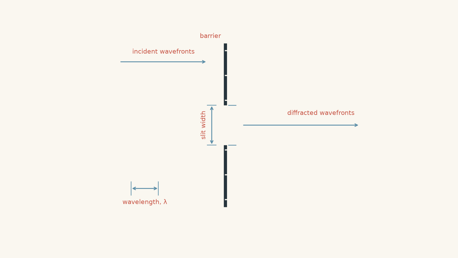
Huygens gives the first part of the explanation: points across the opening act as secondary wavelet sources. Huygens-Fresnel adds the interference between those contributions, allowing the diffraction pattern to be predicted.
For openings much larger than the wavelength, the spreading is small. That’s why ordinary visible-light shadows often look quite sharp even though light has wave behaviour.
Interference gives an even sharper test
Two coherent light waves can overlap and produce bright and dark regions.
The dark regions are especially important. Light from both paths is reaching that region, yet their electric fields can cancel because the waves arrive out of phase.
A simple model of independent classical particles gives no natural reason why opening a second route for light should create regularly spaced places where fewer detections occur.
Wave superposition does.
This is why interference and diffraction became powerful evidence for the wave behaviour of light.
There is one final piece of precision worth keeping. These experiments do not establish that light is only a classical wave. Later experiments reveal particle-like behaviour as well. Modern physics has to account for both.
08The misconceptions worth catching
“A ray and a wavefront are the same thing”
They are almost opposites geometrically.
The wavefront joins points of equal phase. The ray shows the direction of propagation and is perpendicular to the wavefront in the ordinary isotropic media used in HSC problems.
“Light slows down, so its frequency decreases”
At a stationary boundary, its frequency remains fixed.
The wavelength changes:
\[ v=f\lambda. \]
Lower \(v\) with unchanged \(f\) means lower \(\lambda\).
“Every secondary wavelet adds extra light”
The wavelets are parts of a propagation construction, not independent energy generators.
Where contributions overlap, their phases matter. They may reinforce or cancel.
“Wave evidence proves light cannot be particle-like”
It doesn’t.
Diffraction and interference establish wave-like behaviour extremely clearly. Other experiments require a photon description. A good physical model must match the observation being tested rather than forcing every experiment into one nineteenth-century picture.
09Questions and solutions
Question 1
Light of wavelength \(450\text{ nm}\) in air enters glass normally. The refractive index of the glass is \(1.50\).
Calculate:
a. the speed of light in the glass
b. the frequency of the light
c. the wavelength in the glass
d. what happens to the direction and spacing of its wavefronts.
Take \(c=3.00\times10^8\text{ m s}^{-1}\).
Solution 1
The light travels at \(2.00\times10^8\text{ m s}^{-1}\) in the glass, keeps a frequency of \(6.67\times10^{14}\text{ Hz}\), and has a glass wavelength of \(300\text{ nm}\). It does not change direction because it enters normally.
For the speed,
\[ v=\frac{c}{n} =\frac{3.00\times10^8}{1.50} =2.00\times10^8\text{ m s}^{-1}. \]
The frequency is set by the source and remains unchanged at the stationary boundary. Calculate it using the wavelength in air:
\[ f=\frac{c}{\lambda_{\text{air}}} =\frac{3.00\times10^8}{450\times10^{-9}} =6.67\times10^{14}\text{ Hz}. \]
Then
\[ \lambda_{\text{glass}} =\frac{v_{\text{glass}}}{f} =\frac{2.00\times10^8}{6.67\times10^{14}} =3.00\times10^{-7}\text{ m} =300\text{ nm}. \]
The wavefronts therefore become more closely spaced in the glass.
The tempting mistake is to reduce the frequency because the light has slowed down. The boundary does not change the oscillation rate; it changes the wavelength.
Question 2
A plane light wave travels from air into glass of refractive index \(1.60\) at an incident angle of \(42.0^\circ\).
a. Calculate the refracted angle.
b. In \(2.00\text{ ns}\), calculate how far light could travel through air and how far a secondary wavelet could grow through the glass.
c. Use these results to explain the Huygens construction physically.
Solution 2
The refracted angle is \(24.7^\circ\), and the smaller distance travelled in the glass causes the wavefront to pivot towards the normal.
For the refracted angle,
\[ n_1\sin i=n_2\sin r, \]
so
\[ \sin r =\frac{1.00\sin42.0^\circ}{1.60} =0.418. \]
Therefore,
\[ r=24.7^\circ. \]
The distance travelled through air during \(2.00\text{ ns}\) is
\[ d_{\text{air}} =vt =(3.00\times10^8)(2.00\times10^{-9}) =0.600\text{ m}. \]
First find the speed in glass:
\[ v_{\text{glass}} =\frac{3.00\times10^8}{1.60} =1.875\times10^8\text{ m s}^{-1}. \]
The secondary wavelet in the glass therefore grows by
\[ d_{\text{glass}} =(1.875\times10^8)(2.00\times10^{-9}) =0.375\text{ m}. \]
One part of the original wavefront can therefore progress \(0.600\text{ m}\) through air in the chosen time while the part already inside the glass progresses only \(0.375\text{ m}\).
The new tangent wavefront has to rotate to join those unequal advances. Its perpendicular ray therefore bends towards the normal.
A tempting approach is simply to memorise “higher \(n\) means towards the normal”. Huygens tells you why: higher refractive index means lower speed, smaller secondary wavelets, and therefore a rotated wavefront.
Question 3
Light travelling through water of refractive index \(1.33\) reaches a flat water-air boundary at an incident angle of \(55.0^\circ\).
a. Attempt to calculate the refracted angle using Snell’s law.
b. Calculate the critical angle for the water-air boundary.
c. Explain, using Huygens’ construction, why the failed calculation has a physical meaning rather than being a calculator error.
Solution 3
There is no propagating refracted ray: \(55.0^\circ\) is greater than the critical angle of approximately \(48.8^\circ\), so total internal reflection occurs.
Apply Snell’s law:
\[ 1.33\sin55.0^\circ=1.00\sin r. \]
This gives
\[ \sin r=1.33\sin55.0^\circ\approx1.09. \]
But no real angle has a sine greater than 1.
That impossibility is the physics.
At the critical angle, the refracted ray would travel along the boundary, so \(r=90^\circ\). Therefore,
\[ 1.33\sin c=1.00\sin90^\circ, \]
giving
\[ \sin c=\frac{1.00}{1.33}=0.752, \]
and
\[ c=48.8^\circ. \]
Since
\[ 55.0^\circ>48.8^\circ, \]
there is no ordinary transmitted propagating ray.
Huygens’ construction reaches the same conclusion geometrically. Light travels faster in air than in water, so a secondary wavelet on the air side grows more quickly. At sufficiently large incidence angles, there is no possible forward tangent corresponding to a real refracted angle.
The tempting reaction is to treat \(\sin r>1\) as evidence of an arithmetic mistake. Instead, it marks the boundary of what the refracted-ray construction can physically produce.
Question 4
A plane wave of wavelength \(600\text{ nm}\) travels through air. A glass plate of refractive index \(1.50\) and thickness \(3.00\,\mu\text{m}\) covers only the upper half of the beam. Both faces of the plate are perpendicular to the direction of travel.
After leaving the plate, both halves of the beam are again travelling through air.
a. Does the glass-covered half emerge in a different direction from the uncovered half?
b. Calculate the optical path difference introduced by the glass relative to the same thickness of air, and hence determine their phase difference modulo one full cycle.
c. A student argues: “The two halves are \(180^\circ\) out of phase, so the entire beam must cancel and disappear.” Evaluate this claim.
Solution 4
Both halves emerge in the same direction, but the glass-covered half is delayed by \(2.5\) wavelengths, making it \(180^\circ\) out of phase modulo a complete cycle. The whole beam does not disappear because phase cancellation requires the fields to overlap at the same place.
There is no change of direction because the light strikes both parallel glass faces normally. The speed and wavelength change while the wave is inside the glass, but the ray remains perpendicular to each interface.
The extra optical path introduced by replacing air with glass is
\[ \Delta L=(n-1)t. \]
Therefore,
\[ \Delta L =(1.50-1.00)(3.00\,\mu\text{m}) =1.50\,\mu\text{m}. \]
Since
\[ \lambda=600\text{ nm}=0.600\,\mu\text{m}, \]
the number of extra wavelengths is
\[ \frac{\Delta L}{\lambda} =\frac{1.50}{0.600} =2.50. \]
Two complete cycles make no difference to the relative phase, leaving half a cycle:
\[ \Delta\phi=180^\circ. \]
The glass-covered half therefore emerges half a cycle out of phase with the uncovered half.
But the conclusion that the whole beam disappears is wrong.
Immediately after the plate, the two halves occupy different parts of space. Being \(180^\circ\) out of phase does not cause cancellation unless the waves are superposed at the same location with suitable amplitudes.
Once diffraction causes contributions from the two regions to overlap, their phase difference affects the resulting interference pattern. Energy is redistributed between regions rather than the entire beam simply vanishing.
This exposes an important limit of a purely geometric Huygens construction. Knowing the shape and direction of wavefronts is not enough to predict brightness. Phase and superposition, as included in the Huygens-Fresnel picture, are also required.
Question 5
Monochromatic light of wavelength \(500\text{ nm}\) illuminates two narrow slits. At a particular point \(P\) on a distant screen, the path from slit \(S_1\) is \(250\text{ nm}\) longer than the path from slit \(S_2\).
A thin glass plate of refractive index \(1.50\) is then placed across \(S_1\).
a. Before the plate is inserted, determine whether \(P\) is a constructive or destructive interference position.
b. Find the smallest non-zero plate thickness that changes \(P\) into a constructive interference position. Assume the plate replaces the same thickness of air.
c. The source is then attenuated until individual photons are detected one at a time. After many detections, the same fringe pattern builds up statistically. Explain what this result tells us about the wave evidence, and what it does not tell us.
Solution 5
Point \(P\) is initially destructive, a \(500\text{ nm}\) glass thickness is the smallest plate that makes it constructive, and the eventual single-photon interference pattern demonstrates wave-like phase behaviour without implying that light is only a classical continuous wave.
Initially, the path difference is
\[ \Delta L=250\text{ nm}. \]
Since
\[ \lambda=500\text{ nm}, \]
this is
\[ \Delta L=\frac{\lambda}{2}. \]
A half-wavelength path difference corresponds to a phase difference of \(180^\circ\), so the two contributions arrive destructively at \(P\).
The glass plate adds optical path relative to air of
\[ \Delta L_{\text{plate}}=(n-1)t. \]
To change the original half-wavelength path difference into the nearest whole-wavelength difference, the plate must add another
\[ \frac{\lambda}{2}=250\text{ nm}. \]
Therefore,
\[ (1.50-1.00)t=250\text{ nm}, \]
so
\[ 0.50t=250\text{ nm}, \]
and
\[ t=500\text{ nm}. \]
The total effective path difference is then
\[ 250\text{ nm}+250\text{ nm}=500\text{ nm}=\lambda, \]
which is constructive.
The deeper part is what happens when photons arrive individually.
It is tempting to reason that interference should disappear because two classical waves are no longer arriving together at the screen. Experimentally, however, individual detections accumulate into an interference distribution when the experimental arrangement preserves the required coherence.
That means a simple picture of independent classical particles taking one geometrical route and carrying no phase information is incomplete. The probability distribution retains wave-like interference.
But the individual detections are still localised. The experiment therefore does not establish that light is merely a classical continuous wave either.
Huygens’ construction remains valuable for understanding how wavefronts propagate. Huygens-Fresnel reasoning adds phase and interference. A complete modern description goes further again to account for the localised detection of photons.
The fair conclusion from the evidence is narrower and stronger: light displays wave behaviour, and any successful theory of light has to reproduce it.
10What this unlocks next
Once you can construct a new wavefront from secondary wavelets, diffraction stops looking like a mysterious exception to straight-line travel. You can see why spreading becomes important when the opening is comparable with the wavelength in Diffraction of Light: Slit Width, Wavelength and HSC Physics.
The next step is to keep Huygens’ secondary waves but track their phase as they overlap. That turns wavefront propagation into the bright and dark fringes studied in Double-Slit Interference and Fringe Evidence for HSC Physics.