
Polarisation of Light and Transverse Waves for HSC Physics
Learn how polarisation shows that light has transverse properties, how linear polarisers affect intensity, and how Malus's law explains transmission through multiple polarisers.
Shine ordinary light through one ideal polariser and rotate it. The brightness barely changes. Put a second polariser behind the first and rotate that one instead. Now the light can fade all the way to darkness.
That is already strange. The second sheet has not changed the light’s direction of travel. It has only been rotated around that direction.
So predict this first: if light behaved like a longitudinal wave, with its oscillations pointing forwards and backwards along its direction of travel, why should rotating a filter around the beam make any difference?
It shouldn’t. A longitudinal oscillation has no up-down or left-right orientation for the filter to select.
Yet light does respond to that rotation. That observation is the key reason polarisation supports a transverse-wave model.
01What has to be oscillating?
Picture a beam travelling horizontally towards the right.
A wave needs some quantity that changes as the wave travels. For a wave on a rope, the rope itself moves. For sound in air, the pressure and density change.
For light, the quantities that oscillate are the electric field and magnetic field.
In the electromagnetic-wave model:
- the wave travels in one direction,
- the electric field oscillates perpendicular to that direction,
- the magnetic field also oscillates perpendicular to the direction of travel,
- and the electric and magnetic fields are perpendicular to each other.
If the beam travels in the \(x\)-direction, its electric field might oscillate vertically in the \(y\)-direction.
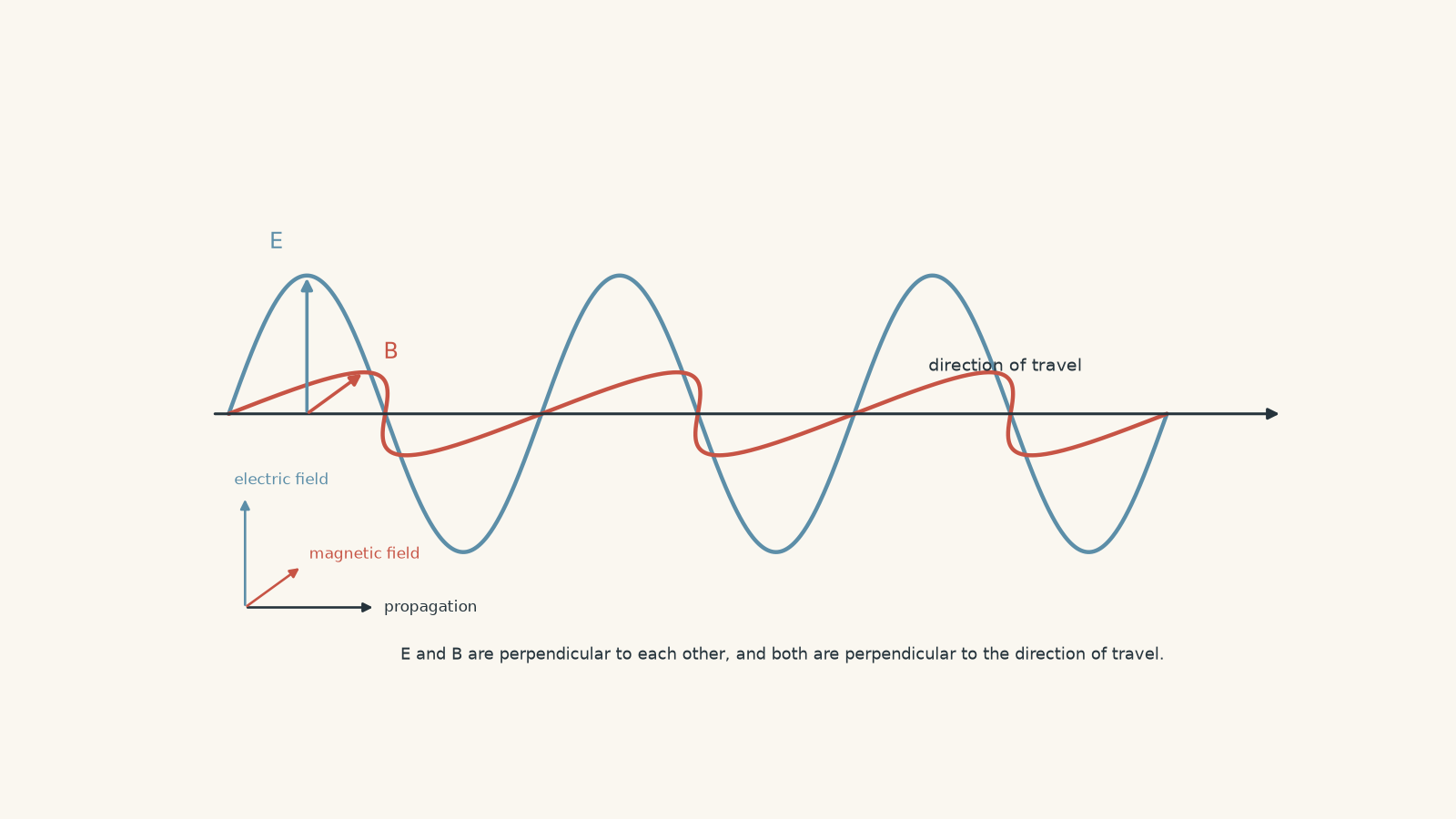
For polarisation, we normally focus on the electric field. It is the direction of the electric-field oscillation that we mean when we say light is vertically or horizontally polarised.
02Why a transverse wave can be polarised
Imagine people walking straight down a corridor while swinging pool noodles from side to side.
One person swings their noodle vertically. Another swings it horizontally. Both people still walk forwards.
A gate could be built that only allows one swing direction to continue through.
That gives us a useful picture of a transverse wave. The direction of oscillation can change while the direction of travel stays the same.
The analogy has a limit. A polariser is not literally a mechanical gate with gaps that electromagnetic waves squeeze through. Its material interacts with different electric-field components differently. The useful part of the analogy is simply that there is a direction of oscillation perpendicular to the direction of travel.
A longitudinal wave does not have that freedom.
For a longitudinal wave travelling to the right, the oscillation is also along the right-left direction. Rotating something around the beam axis does not reveal a new oscillation direction.
That is why polarisation is evidence that light has a transverse character.
03Unpolarised and linearly polarised light
Ordinary light from many sources is unpolarised.
That does not mean the electric field has no direction. At any instant, the electric field is still perpendicular to the direction of travel. Instead, there is no single preferred direction maintained over time.
You can picture many wave contributions with electric fields pointing in different directions across the plane perpendicular to the beam.
A linear polariser selects one direction from those possibilities.
The direction it transmits is called its transmission axis.
After unpolarised light passes through an ideal linear polariser, the transmitted light is linearly polarised along that axis.
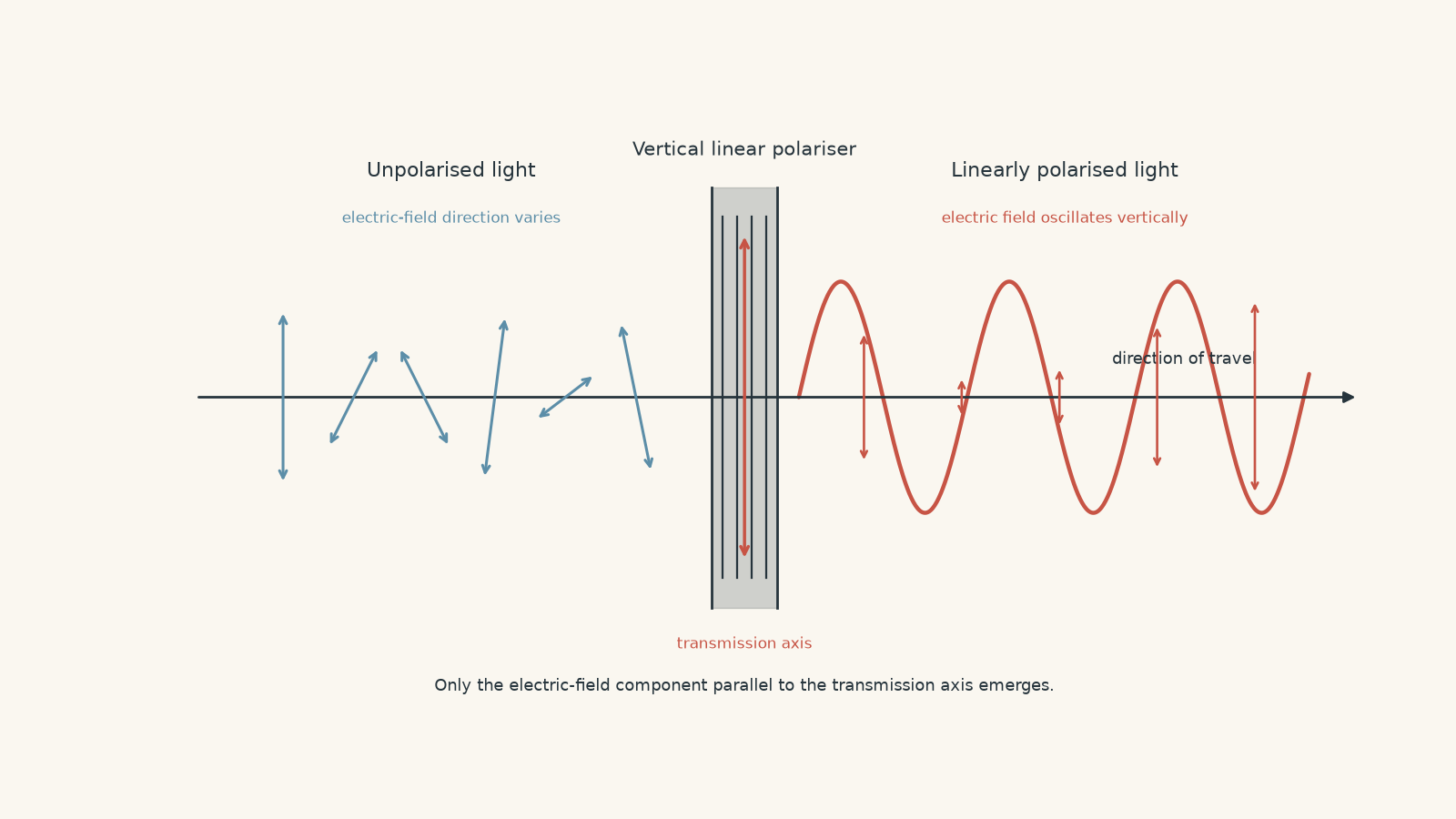
For an ideal polariser, the average transmitted intensity is half the incident intensity:
\[ I_1=\frac{I_0}{2} \]
where:
- \(I_0\) is the intensity of the unpolarised incident light, in \(\text{W m}^{-2}\),
- \(I_1\) is the intensity after the first ideal polariser.
Why half?
Because the incoming electric-field directions are spread across all transverse orientations. On average, half of the incident intensity belongs to the component selected by one polarisation axis.
Real polarising materials also lose some light through reflection and absorption, so the measured value can be less than this ideal result.
04What happens when you add a second polariser?
Suppose the first polariser produces vertically polarised light.
Now place a second polariser behind it.
If the second transmission axis is also vertical, the light passes through with maximum intensity.
Rotate the second polariser by \(90^\circ\), so its axis is horizontal. Ideally, no light emerges.
At an angle between these extremes, only part of the electric field lies along the second polariser’s transmission axis.
This is where the geometry matters.
If the incoming electric-field amplitude is \(E_0\), and the angle between the incoming polarisation direction and the new transmission axis is \(\theta\), the transmitted field component is
\[ E=E_0\cos\theta \]
Light intensity is proportional to the square of the electric-field amplitude, so
\[ I=I_{\text{in}}\cos^2\theta \]
This relationship is Malus’s law.
Here:
- \(I_{\text{in}}\) is the intensity of the already linearly polarised light reaching the polariser,
- \(I\) is the transmitted intensity,
- \(\theta\) is the angle between the incoming polarisation direction and the polariser’s transmission axis.
The angle is not usually measured from vertical or horizontal. It is the angle between the two relevant polarisation directions.
That distinction saves a lot of mistakes.
Worked example: Light through an analysing polariser
A beam of linearly polarised light has an intensity of \(80.0\ \text{W m}^{-2}\). It reaches a second polariser whose transmission axis is \(30^\circ\) from the beam’s polarisation direction. Calculate the transmitted intensity.
Step 1
The light is already linearly polarised, so there is no initial one-half factor. We use Malus’s law directly.
\[ I=I_{\text{in}}\cos^2\theta \]
Step 2
\[ I=(80.0)\cos^2(30^\circ) \]
Since \(\cos 30^\circ \approx 0.866\),
\[ I=(80.0)(0.866)^2 =(80.0)(0.750) =60.0\ \text{W m}^{-2} \]
Step 3
The polariser transmits \(75\%\) of the incoming intensity because the electric-field amplitude along its axis is \(0.866\) of the original amplitude, and intensity depends on amplitude squared.
The common mistake here is to calculate \(80.0\cos30^\circ\). That would treat intensity as though it were the electric-field amplitude. It isn’t.
05Why crossed polarisers can block light
Now make the two polariser axes perpendicular.
If light leaves the first polariser vertically polarised, the second polariser has a horizontal transmission axis.
For the second polariser,
\[ \theta=90^\circ \]
so
\[ I=I_{\text{in}}\cos^2(90^\circ)=0 \]
This near-extinction is much more useful than simply saying that “a polariser absorbs some light”.
The second polariser responds to the directional state produced by the first.
That is the important evidence.
A longitudinal-wave model has a problem here. If the oscillation were only along the direction of travel, there would be no transverse vertical state for the first polariser to prepare and no transverse horizontal state for the second one to reject.
06The strange result: adding a polariser can let more light through
Suppose two polarisers are crossed at \(90^\circ\), so ideally no light gets through.
Now insert a third polariser between them with its axis at \(45^\circ\).
Predict what happens.
It is tempting to say that adding another light-absorbing object must make the transmitted intensity stay at zero, or perhaps become “even more zero”.
Instead, light gets through.
The middle polariser changes the polarisation direction presented to the final polariser.
This does not create energy. Each polariser still reduces the intensity reaching it. But the middle polariser prevents the final polariser from receiving a state exactly perpendicular to its own axis.
Worked example: Three polarisers
Unpolarised light with intensity \(160\ \text{W m}^{-2}\) passes through three ideal polarisers. Their transmission axes are at \(0^\circ\), \(45^\circ\), and \(90^\circ\), respectively. Calculate the final intensity.
Step 1
The incident light is unpolarised, so
\[ I_1=\frac{I_0}{2} =\frac{160}{2} =80.0\ \text{W m}^{-2} \]
The emerging light is now polarised at \(0^\circ\).
Step 2
The relative angle is \(45^\circ\).
\[ I_2=I_1\cos^2(45^\circ) =(80.0)(0.500) =40.0\ \text{W m}^{-2} \]
The light leaving this polariser is now polarised at \(45^\circ\).
That last sentence matters. Do not keep treating it as though it were still polarised at \(0^\circ\).
Step 3
The incoming light is at \(45^\circ\), so the relative angle is again \(45^\circ\).
\[ I_3=I_2\cos^2(45^\circ) =(40.0)(0.500) =20.0\ \text{W m}^{-2} \]
So the final intensity is
\[ I_3=20.0\ \text{W m}^{-2} \]
Without the middle polariser, the first and final axes would differ by \(90^\circ\), giving zero transmitted intensity.
The middle polariser does not add light. It changes the polarisation direction in a way that leaves a component available to the final polariser.
07What polarisation actually tells us about light
It helps to separate three observations.
| Observation | What it tells us |
|---|---|
| One ideal polariser transmits about half of unpolarised light | The polariser selects one transverse electric-field direction from light with no preferred linear polarisation |
| Two aligned polarisers give high transmission, while crossed polarisers give near-zero transmission | The light leaving the first polariser carries a directional polarisation state |
| Transmission changes as the relative angle changes | The relevant direction exists in the plane perpendicular to the beam and follows a projection rule |
The important phrase is relative angle.
If you rotate both polarisers together by the same amount, their angle relative to one another has not changed. The ideal transmitted intensity therefore stays the same.
So the effect is not simply “vertical objects transmit light better than horizontal objects”. There is no universally special vertical direction.
The beam acquires a polarisation direction, and the next polariser responds to its orientation relative to that direction.
08The most tempting misconception
A student might say:
Light is transverse because a polariser has tiny vertical gaps that only let vertically moving light through.
The first half of that idea is heading in the right direction. The second half is too mechanical.
The transmission axis describes which electric-field direction emerges from the polariser. The microscopic interaction inside a real polarising material involves how charges in the material respond to components of the electric field.
So do not imagine a light wave physically weaving between fence posts.
For HSC reasoning, the safer chain is:
- Light has an electric field perpendicular to its direction of travel.
- A linear polariser selects a particular electric-field orientation.
- A second polariser transmits an amount that depends on its angle relative to that orientation.
- This dependence on transverse direction is consistent with a transverse electromagnetic wave and not with a purely longitudinal-wave model.
09Does polarisation prove that light is only a classical wave?
No. That would claim more than the evidence gives us.
Polarisation strongly supports the transverse nature of light and is naturally described using the wave model. But modern physics also describes light in terms of photons, and photons can have polarisation states.
Different experiments test different parts of our models.
For example, double-slit interference shows how light produces interference through superposition, while diffraction shows how waves spread when their path is restricted.
Polarisation adds a different piece of evidence: the oscillation has direction perpendicular to the direction of propagation.
10Questions and solutions
Question 1
A beam of light travels towards a linear polariser. Explain why the observation that transmitted intensity changes when a second polariser is rotated supports a transverse-wave model of light rather than a purely longitudinal-wave model.
Solution 1
The changing intensity supports a transverse-wave model because the light must carry an oscillation direction perpendicular to its direction of travel.
The first polariser prepares light with its electric field oscillating along one transverse direction. The second polariser then transmits a component of that field depending on the angle between its transmission axis and the incoming polarisation direction.
When the axes are parallel, transmission is greatest. When they are perpendicular, ideal transmission falls to zero.
A purely longitudinal wave oscillates only along its direction of propagation. It has no independent up-down or left-right oscillation direction for a rotated polariser to select.
The tempting explanation is simply that the second polariser “blocks more light when rotated”. That does not identify the important evidence. What matters is that transmission depends on a direction in the plane perpendicular to the beam.
Question 2
Unpolarised light has an intensity of \(300\ \text{W m}^{-2}\). It passes through two ideal polarisers whose transmission axes differ by \(60^\circ\).
Calculate the final intensity.
The two polarisers are then rotated together by \(25^\circ\), without changing the \(60^\circ\) angle between them. State what happens to the final intensity and explain why.
Solution 2
The final intensity is \(37.5\ \text{W m}^{-2}\), and rotating both polarisers together does not change it.
The first polariser receives unpolarised light, so its transmitted intensity is
\[ I_1=\frac{I_0}{2} =\frac{300}{2} =150\ \text{W m}^{-2} \]
The light leaving it is linearly polarised along the first polariser’s transmission axis.
For the second polariser, the relevant angle is \(60^\circ\). Using Malus’s law,
\[ I_2=I_1\cos^2\theta =(150)\cos^2(60^\circ) =(150)(0.25) =37.5\ \text{W m}^{-2} \]
Rotating both polarisers together leaves their relative angle at \(60^\circ\), so the final intensity remains
\[ 37.5\ \text{W m}^{-2} \]
A tempting mistake is to use the new absolute angles of the polarisers measured from vertical. Malus’s law does not care which way the laboratory walls are pointing. It depends on the angle between the incoming polarisation direction and the next transmission axis.
Question 3
Unpolarised light of intensity \(I_0\) passes through three ideal polarisers.
The first transmission axis is at \(0^\circ\), the third is at \(90^\circ\), and the middle polariser can be placed at any angle \(\theta\) between them.
Determine the value of \(\theta\) that gives the greatest final intensity and find that intensity as a fraction of \(I_0\).
Explain why this arrangement can transmit light even though the first and third polarisers are crossed.
Solution 3
The maximum occurs when the middle polariser is at \(45^\circ\), and the final intensity is \(I_0/8\).
After the first polariser,
\[ I_1=\frac{I_0}{2} \]
The angle from the first polariser to the middle one is \(\theta\), so
\[ I_2=\frac{I_0}{2}\cos^2\theta \]
The light leaving the middle polariser is now polarised at \(\theta\).
The angle from that direction to the final \(90^\circ\) axis is \(90^\circ-\theta\). Therefore,
\[ I_3=\frac{I_0}{2}\cos^2\theta\cos^2(90^\circ-\theta) \]
Using \(\cos(90^\circ-\theta)=\sin\theta\),
\[ I_3=\frac{I_0}{2}\cos^2\theta\sin^2\theta \]
The two factors are balanced when
\[ \theta=45^\circ \]
At \(45^\circ\),
\[ I_3 =\frac{I_0}{2} \left(\frac{1}{2}\right) \left(\frac{1}{2}\right) =\frac{I_0}{8} \]
The tempting route is to think the best position should place the middle polariser close to either the first or the third, because that reduces the loss at one step. But doing that increases the angular mismatch at the other step.
At \(45^\circ\), the two projection losses are shared equally.
Without the middle polariser, the first and third axes differ by \(90^\circ\), so the final intensity is zero. With the middle polariser present, the light is first projected into the intermediate \(45^\circ\) state and then has a non-zero component along the final \(90^\circ\) axis.
Question 4
A student investigates an unknown beam with an intensity of \(90.0\ \text{W m}^{-2}\).
They are told that their analyser is an ideal, lossless linear polariser and that the source intensity stays constant during the experiment.
As the analyser is rotated, the maximum recorded transmitted intensity is \(72.0\ \text{W m}^{-2}\), while the minimum is exactly \(0\ \text{W m}^{-2}\).
The student says, “The source must be \(80\%\) linearly polarised because \(72/90=0.80\).”
Show why the measurements cannot all be correct under the stated assumptions. Identify the constraint the student’s calculation misses.
Solution 4
The data are inconsistent with the stated ideal conditions; the source cannot simply be labelled \(80\%\) linearly polarised from the ratio \(72/90\).
Consider what the zero minimum tells us first.
A beam containing any unpolarised component would send some intensity through an ideal analyser at every orientation. The unpolarised part would contribute half of its intensity regardless of the analyser’s angle.
Therefore, an exact minimum of
\[ 0\ \text{W m}^{-2} \]
means that, under the ideal assumptions, there can be no unpolarised component. The beam must be fully linearly polarised.
But if the incident beam is fully linearly polarised with total intensity
\[ 90.0\ \text{W m}^{-2}, \]
then aligning an ideal, lossless analyser with that polarisation direction gives
\[ I_{\max} =I_{\text{in}}\cos^2(0^\circ) =90.0\ \text{W m}^{-2} \]
not \(72.0\ \text{W m}^{-2}\).
So the two measurements
\[ I_{\max}=72.0\ \text{W m}^{-2} \]
and
\[ I_{\min}=0 \]
cannot both come from a constant \(90.0\ \text{W m}^{-2}\) beam and an ideal lossless analyser.
At least one stated assumption must fail. For example, the analyser may have additional losses, the incident intensity may have changed, or one of the measurements may be inaccurate.
The tempting \(72/90=80\%\) calculation uses only the maximum reading. It ignores the minimum reading, which places an additional constraint on the possible polarisation state.
This is an important physics habit: a proposed model has to satisfy all the observations at once.
Question 5
Two students propose different models for a polarisation experiment.
Model A says that light carries a transverse electric-field direction. A polariser projects the field onto its transmission axis, so the light leaving the polariser has a new polarisation direction.
Model B says that light is purely longitudinal. Each polarising sheet can still absorb different amounts of light depending on how the sheet is rotated in the laboratory, but a sheet does not create any directional state in the transmitted beam.
Unpolarised light of intensity \(I_0\) passes through a polariser at \(20^\circ\), followed by one at \(110^\circ\). No light is detected.
A third ideal polariser is then inserted between them at \(65^\circ\), and light is detected.
Calculate the intensity predicted by Model A. Then explain why the result creates a serious problem for Model B, even if Model B is allowed to claim that individual sheets have direction-dependent absorption.
Solution 5
Model A predicts a final intensity of \(I_0/8\), while Model B fails because inserting the middle polariser changes the state presented to the final polariser, not merely the amount of light.
Start with Model A.
The first polariser receives unpolarised light, so
\[ I_1=\frac{I_0}{2} \]
The light leaving it is polarised at \(20^\circ\).
The middle polariser is at \(65^\circ\), giving a relative angle of
\[ 65^\circ-20^\circ=45^\circ \]
Using Malus’s law,
\[ I_2 =\frac{I_0}{2}\cos^2(45^\circ) =\frac{I_0}{2}\left(\frac{1}{2}\right) =\frac{I_0}{4} \]
The light leaving the middle polariser is now polarised at \(65^\circ\).
The final polariser is at \(110^\circ\), again giving a relative angle of
\[ 110^\circ-65^\circ=45^\circ \]
Therefore,
\[ I_3 =\frac{I_0}{4}\cos^2(45^\circ) =\frac{I_0}{4}\left(\frac{1}{2}\right) =\frac{I_0}{8} \]
Without the middle polariser, the angle between \(20^\circ\) and \(110^\circ\) is \(90^\circ\), so Model A predicts
\[ I=0 \]
exactly as observed.
The surprising part is that adding an extra absorbing device changes the final intensity from zero to a non-zero value.
A simple version of Model B cannot explain this by saying only that each sheet has its own angle-dependent transmission.
Before the middle sheet is inserted, the final sheet at \(110^\circ\) blocks the light coming from the first sheet. If the middle sheet merely removes some intensity but does not change any directional property of the transmitted light, the final sheet should still encounter the same kind of longitudinal wave and should still block it according to the same rule.
Instead, the middle polariser changes what the final polariser can transmit.
That means the beam emerging from a polariser carries information about an orientation. The next polariser responds to that prepared orientation.
A student may try to rescue the longitudinal model by inventing an extra directional property that is passed from one polariser to the next. But once that property can point at \(20^\circ\), \(65^\circ\), or \(110^\circ\) in the plane perpendicular to the beam, the model has effectively introduced the transverse degree of freedom it was supposed to avoid.
That is the deeper reason polarisation supports the transverse-wave model. It is not merely that rotated sheets transmit different amounts of light. A polariser prepares an oriented state, and later polarisers respond to that state through their relative orientation.
That transverse electric-field picture is the useful next step into the full electromagnetic model of light, where the electric field, magnetic field, and direction of propagation form three mutually perpendicular directions.