
Malus’ Law for HSC Physics: Intensity and Polariser Angles
Learn how to use Malus' law for plane-polarised light, choose the correct angle, and track intensity through multiple polarisers.
Put two ideal polarising filters in the same direction and light gets through. Now rotate the second filter by \(60^\circ\). What fraction of the maximum intensity do you expect: two-thirds, one-half, or one-quarter?
It is one-quarter. The angle does not reduce the intensity directly. First, the second polariser reduces the electric-field amplitude by a projection. Intensity then depends on the square of that amplitude. That two-step idea is Malus’ law.
01What the analyser actually does
Plane-polarised light has an electric field oscillating in one fixed direction. If that picture is unfamiliar, refresh it first in Polarisation of Light and Transverse Waves for HSC Physics.
Now imagine the electric-field amplitude as an arrow. A polarising filter has a transmission axis. Only the component of the electric field parallel to that axis is transmitted.
This is the same geometry as taking the shadow of an arrow onto a line.
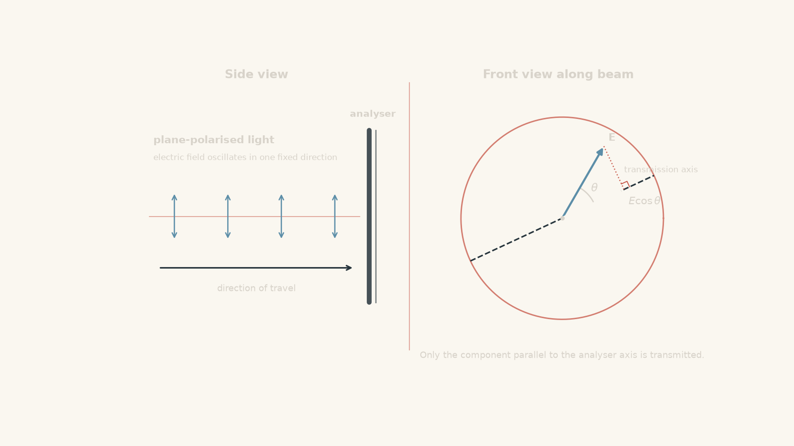
Suppose the electric field and transmission axis are \(45^\circ\) apart. Before calculating, predict what happens.
The transmitted electric-field amplitude is about \(70.7\%\) of its maximum value because \(\cos 45^\circ = 0.707\). It is tempting to say the transmitted intensity is therefore also \(70.7\%\).
That is the important trap. Light intensity is proportional to the square of electric-field amplitude.
So an amplitude of \(0.707\) of maximum gives an intensity of
\[ (0.707)^2 = 0.500 \]
or \(50.0\%\) of maximum.
The arrow-shadow picture is useful because the projection is real mathematics. It becomes incomplete if you imagine that the filter literally chops a geometric piece off the light. What is being resolved is the oscillating electric field.
02From the field projection to Malus’ law
Let \(E_{\max}\) be the electric-field amplitude when the incoming plane of polarisation is aligned with the analyser’s transmission axis.
If the angle between them is \(\theta\), the transmitted electric-field amplitude is
\[ E = E_{\max}\cos\theta \]
Intensity \(I\) is proportional to the square of electric-field amplitude:
\[ I\propto E^2 \]
Therefore,
\[ \frac{I}{I_{\max}} = \frac{E^2}{E_{\max}^2} = \cos^2\theta \]
which gives Malus’ law:
\[ I=I_{\max}\cos^2\theta \]
Here:
| Symbol | Meaning |
|---|---|
| \(I\) | intensity transmitted through the analyser, usually in \(\mathrm{W\,m^{-2}}\) |
| \(I_{\max}\) | maximum transmitted intensity, occurring when the incoming polarisation and analyser axis are aligned |
| \(\theta\) | angle between the incoming plane of polarisation and the analyser’s transmission axis |
The word between matters. If the incoming light is polarised \(20^\circ\) above the horizontal and the analyser axis is \(70^\circ\) above the horizontal, then
\[ \theta=70^\circ-20^\circ=50^\circ \]
You do not put \(70^\circ\) into Malus’ law.
For ideal polarisers, these values are worth recognising:
| \(\theta\) | \(\cos^2\theta\) | \(I/I_{\max}\) |
|---|---|---|
| \(0^\circ\) | \(1\) | \(1\) |
| \(30^\circ\) | \(0.75\) | \(0.75\) |
| \(45^\circ\) | \(0.50\) | \(0.50\) |
| \(60^\circ\) | \(0.25\) | \(0.25\) |
| \(90^\circ\) | \(0\) | \(0\) |
Notice how badly a linear model would fail. Doubling the angle from \(30^\circ\) to \(60^\circ\) does not halve the intensity. It changes the transmitted fraction from \(0.75\) to \(0.25\).
Worked example: finding the correct relative angle
A plane-polarised beam has an intensity of \(85.0\ \mathrm{W\,m^{-2}}\). Its plane of polarisation is \(20^\circ\) above the horizontal. It passes through an ideal analyser whose transmission axis is \(70^\circ\) above the horizontal. Find the transmitted intensity.
Step 1
\[ \theta=70^\circ-20^\circ=50^\circ \]
Step 2
\[ \begin{aligned} I&=I_{\max}\cos^2\theta\\ &=(85.0)\cos^2(50^\circ)\\ &=(85.0)(0.4132)\\ &=35.1\ \mathrm{W\,m^{-2}} \end{aligned} \]
Step 3
The analyser transmits about \(41.3\%\) of the maximum intensity. The result is much less than \(85.0\ \mathrm{W\,m^{-2}}\) because the analyser is \(50^\circ\), not \(20^\circ\), away from the incoming polarisation direction.
03What exactly is \(I_{\max}\)?
A common mistake is to treat \(I_{\max}\) as “whatever intensity appeared at the beginning of the question”.
That is not always correct.
For Malus’ law, \(I_{\max}\) is the maximum intensity that could be transmitted by the analyser for the light reaching that analyser. For an ideal analyser receiving already plane-polarised light, this is simply the incident intensity.
If the light is initially unpolarised, there is no single polarisation direction to put into Malus’ law. An ideal first polariser transmits half of the unpolarised intensity:
\[ I_1=\frac{I_0}{2} \]
where \(I_0\) is the original unpolarised intensity.
The light leaving that first polariser is now plane-polarised along its transmission axis. Malus’ law can then be used for the next polariser.
This gives an important decision rule:
| Situation | What to do |
|---|---|
| Plane-polarised light reaches one analyser | Use \(I=I_{\max}\cos^2\theta\) directly |
| Unpolarised light reaches its first ideal polariser | First use \(I_1=I_0/2\) |
| Light passes through several polarisers | Work through them one at a time |
| A polariser has just been passed | The new polarisation direction is that polariser’s transmission axis |
| Several absolute angles are given | Use the angle between consecutive polarisation directions, not automatically the angle from horizontal |
That fourth row is especially important. Each polariser changes the state of the light entering the next one.
04Several polarisers: update the direction each time
Suppose light leaves a vertical polariser. It is now vertically polarised.
If it next passes through a polariser at \(30^\circ\) to the vertical, the intensity is multiplied by \(\cos^2 30^\circ\). More importantly, the light that survives is now polarised along that second filter’s axis.
A third polariser therefore interacts with the second polariser’s direction, not with the original vertical direction.
That leads to one of the stranger results in this topic: putting an extra polariser between two crossed polarisers can allow light through.
Worked example: light through three polarisers
Unpolarised light has intensity \(160\ \mathrm{W\,m^{-2}}\). It passes through three ideal polarisers. The first is vertical. The second is \(30^\circ\) from vertical towards the horizontal. The third is horizontal. Find the final intensity.
Step 1
The first ideal polariser transmits half:
\[ I_1=\frac{160}{2}=80.0\ \mathrm{W\,m^{-2}} \]
The surviving light is vertically polarised.
Step 2
The relative angle is \(30^\circ\):
\[ \begin{aligned} I_2 &=I_1\cos^2(30^\circ)\\ &=(80.0)(0.75)\\ &=60.0\ \mathrm{W\,m^{-2}} \end{aligned} \]
The light is now polarised along the second polariser’s axis.
Step 3
The second axis is \(30^\circ\) from vertical, so it is \(60^\circ\) from horizontal.
Therefore,
\[ \begin{aligned} I_3 &=I_2\cos^2(60^\circ)\\ &=(60.0)(0.25)\\ &=15.0\ \mathrm{W\,m^{-2}} \end{aligned} \]
Step 4
The final intensity is \(15.0\ \mathrm{W\,m^{-2}}\).
Without the middle polariser, the vertical and horizontal polarisers would be crossed at \(90^\circ\), giving zero transmitted intensity. The middle polariser does not somehow “add light”. It changes the polarisation direction in a smaller step, allowing some light to survive each projection.
05The most tempting Malus’ law mistakes
The algebra is usually short. Most lost marks come from deciding what the symbols mean.
| Tempting move | Why it fails | Better approach |
|---|---|---|
| Use \(I=I_{\max}\cos\theta\) | \(\cos\theta\) gives an electric-field amplitude ratio, not an intensity ratio | Square the cosine |
| Use an angle measured from horizontal automatically | Malus’ law needs the angle between the incoming polarisation and analyser | Find the relative angle first |
| Apply Malus’ law directly to unpolarised light | Unpolarised light has no single plane of polarisation | The first ideal polariser transmits half |
| Keep comparing every polariser with the first one | Each polariser resets the surviving polarisation direction | Work sequentially |
| Assume another polariser must always make the final beam dimmer | An extra polariser can reduce a large angular jump into smaller projections | Track the entire sequence |
| Forget calculator angle mode | HSC questions normally give angles in degrees | Check that the calculator is in degree mode |
There is also no problem if an angle appears larger than \(90^\circ\). A polariser axis is a line, so directions \(180^\circ\) apart describe the same axis, and the square removes the sign of the cosine. Usually it is simplest to use the smallest angle between the two axes.
For example,
\[ \cos^2(120^\circ)=\cos^2(60^\circ)=0.25 \]
06Questions and solutions
Question 1
A plane-polarised beam has intensity \(72.0\ \mathrm{W\,m^{-2}}\). It reaches an ideal analyser whose transmission axis is \(30^\circ\) from the plane of polarisation.
Calculate the transmitted intensity.
Solution 1
The transmitted intensity is \(54.0\ \mathrm{W\,m^{-2}}\).
The incoming light is already plane-polarised, so the stated \(72.0\ \mathrm{W\,m^{-2}}\) is \(I_{\max}\) for an ideal analyser.
Using Malus’ law,
\[ \begin{aligned} I&=I_{\max}\cos^2\theta\\ &=(72.0)\cos^2(30^\circ)\\ &=(72.0)(0.75)\\ &=54.0\ \mathrm{W\,m^{-2}} \end{aligned} \]
The analyser transmits \(75\%\) of the incident intensity.
A tempting error is to use \(\cos30^\circ=0.866\) and report \(86.6\%\). That number describes the transmitted electric-field amplitude as a fraction of its maximum, not the intensity.
Question 2
Unpolarised light of intensity \(200\ \mathrm{W\,m^{-2}}\) passes through three ideal polarisers.
The first polariser is horizontal. The second has its transmission axis \(35^\circ\) above horizontal. The third has its transmission axis \(80^\circ\) above horizontal.
Calculate the final intensity. Explain why using \(80^\circ\) as the angle in a single application of Malus’ law would give the wrong result.
Solution 2
The final intensity is approximately \(33.6\ \mathrm{W\,m^{-2}}\).
The first polariser receives unpolarised light, so it transmits half:
\[ I_1=\frac{200}{2}=100\ \mathrm{W\,m^{-2}} \]
The light is now horizontally polarised.
The second polariser is \(35^\circ\) from horizontal:
\[ \begin{aligned} I_2 &=I_1\cos^2(35^\circ)\\ &=(100)(0.6710)\\ &=67.1\ \mathrm{W\,m^{-2}} \end{aligned} \]
After passing through the second polariser, the light is polarised at \(35^\circ\).
The relative angle to the third polariser is therefore
\[ 80^\circ-35^\circ=45^\circ \]
so
\[ \begin{aligned} I_3 &=I_2\cos^2(45^\circ)\\ &=(67.1)(0.500)\\ &=33.6\ \mathrm{W\,m^{-2}} \end{aligned} \]
The tempting route is to compare the final \(80^\circ\) polariser directly with the original horizontal direction. That ignores what the middle polariser does. The light reaching the final polariser is no longer horizontally polarised; its polarisation was reset to \(35^\circ\).
Question 3
A plane-polarised beam has intensity \(90.0\ \mathrm{W\,m^{-2}}\).
An analyser is adjusted until its transmitted intensity is exactly \(30.0\ \mathrm{W\,m^{-2}}\).
Find the angle between the analyser and the incoming plane of polarisation. The analyser is then rotated a further \(20.0^\circ\) away from the plane of polarisation. Calculate the new transmitted intensity.
Solution 3
The first angle is approximately \(54.7^\circ\), and the final transmitted intensity is approximately \(6.24\ \mathrm{W\,m^{-2}}\).
Initially,
\[ I=I_{\max}\cos^2\theta \]
so
\[ \begin{aligned} 30.0&=(90.0)\cos^2\theta\\ \cos^2\theta&=\frac{1}{3}\\ \cos\theta&=\sqrt{\frac{1}{3}}\\ \theta&=\cos^{-1}\left(\sqrt{\frac{1}{3}}\right)\\ &=54.7^\circ \end{aligned} \]
The analyser is then moved another \(20.0^\circ\) away, giving
\[ \theta_{\text{new}}=54.7^\circ+20.0^\circ=74.7^\circ \]
Therefore,
\[ \begin{aligned} I_{\text{new}} &=(90.0)\cos^2(74.7^\circ)\\ &=6.24\ \mathrm{W\,m^{-2}} \end{aligned} \]
The important feature is how sharply the intensity falls as the analyser approaches \(90^\circ\). An extra \(20^\circ\) does not cause some fixed amount or percentage of intensity loss. Malus’ law is nonlinear.
A common mistake in the inverse calculation is to use \(\cos^{-1}(1/3)\). The quantity \(1/3\) is \(\cos^2\theta\), so the square root must be taken before using inverse cosine.
Question 4
A \(100\ \mathrm{W\,m^{-2}}\) beam is already plane-polarised horizontally. It must emerge vertically polarised after passing through a final vertical analyser.
You may place exactly two additional ideal polarisers before the final analyser. Their transmission axes may be set at any angles between horizontal and vertical.
Choose the two angles that maximise the final intensity, and calculate that maximum intensity.
A student suggests setting both extra polarisers to \(45^\circ\). Explain why that is not the best arrangement.
Solution 4
The maximum occurs when the two extra polarisers are set at \(30^\circ\) and \(60^\circ\), giving a final intensity of approximately \(42.2\ \mathrm{W\,m^{-2}}\).
The beam must change its polarisation from \(0^\circ\) to \(90^\circ\). With two intermediate polarisers, there are three angular changes.
The best arrangement spreads the total \(90^\circ\) rotation evenly:
\[ 0^\circ\rightarrow30^\circ\rightarrow60^\circ\rightarrow90^\circ \]
Each relative angle is therefore \(30^\circ\).
Apply Malus’ law at each polariser:
\[ \begin{aligned} I &=(100) \cos^2(30^\circ) \cos^2(30^\circ) \cos^2(30^\circ)\\ &=(100)(0.75)^3\\ &=42.1875\ \mathrm{W\,m^{-2}}\\ &\approx42.2\ \mathrm{W\,m^{-2}} \end{aligned} \]
Why do equal steps help? A single large angular mismatch causes a severe intensity loss. Splitting the same overall change into smaller rotations allows more of the electric-field component to survive at each stage.
The student’s \(45^\circ,45^\circ\) arrangement gives
\[ 0^\circ\rightarrow45^\circ\rightarrow45^\circ\rightarrow90^\circ \]
so the angular changes are \(45^\circ\), \(0^\circ\), and \(45^\circ\).
Its intensity is
\[ \begin{aligned} I &=(100) \cos^2(45^\circ) \cos^2(0^\circ) \cos^2(45^\circ)\\ &=(100)(0.5)(1)(0.5)\\ &=25.0\ \mathrm{W\,m^{-2}} \end{aligned} \]
The tempting idea is that putting both sheets at \(45^\circ\) creates a perfect “halfway direction”. But the first \(45^\circ\) sheet already turns the surviving polarisation to \(45^\circ\), so the second \(45^\circ\) sheet performs no further rotation. The beam is still left with another \(45^\circ\) jump at the final analyser.
The key constraint is not the average orientation of the sheets. It is the sequence of relative angles experienced by the light.
Question 5
Three identical copies of the same plane-polarised beam are available. Both the beam’s intensity and its plane of polarisation are initially unknown.
A horizontal analyser transmits \(36.0\ \mathrm{W\,m^{-2}}\).
A vertical analyser transmits \(64.0\ \mathrm{W\,m^{-2}}\).
A third analyser, with its transmission axis at \(45^\circ\) above horizontal, transmits \(98.0\ \mathrm{W\,m^{-2}}\).
Determine:
- the original beam intensity, and
- the plane of polarisation relative to the horizontal.
Explain why the horizontal and vertical measurements alone cannot completely determine the polarisation direction.
Solution 5
The original intensity is \(100\ \mathrm{W\,m^{-2}}\), and the beam is polarised \(53.1^\circ\) above the horizontal.
Let the beam’s polarisation make an angle \(\alpha\) with the horizontal.
For the horizontal analyser,
\[ 36.0=I_{\max}\cos^2\alpha \]
For the vertical analyser, the electric-field component is perpendicular to the horizontal component, so
\[ 64.0=I_{\max}\sin^2\alpha \]
Adding the two equations gives
\[ \begin{aligned} 36.0+64.0 &=I_{\max}\left(\cos^2\alpha+\sin^2\alpha\right)\\ 100 &=I_{\max} \end{aligned} \]
because
\[ \cos^2\alpha+\sin^2\alpha=1 \]
So the original beam intensity is
\[ I_{\max}=100\ \mathrm{W\,m^{-2}} \]
Now use the horizontal measurement:
\[ \begin{aligned} 36.0&=(100)\cos^2\alpha\\ \cos^2\alpha&=0.36 \end{aligned} \]
This gives a horizontal electric-field component whose magnitude is \(0.6\) of the total amplitude. The vertical component has magnitude
\[ \sqrt{1-0.36}=0.8 \]
of the total.
At this point there are two mirror-image possibilities. The vertical component could point in the positive or negative direction relative to the chosen horizontal axis. In angle language, the plane of polarisation could be
\[ +53.1^\circ \]
or
\[ -53.1^\circ \]
from horizontal. The latter describes the same axis as \(126.9^\circ\) measured anticlockwise from horizontal.
The first two measurements cannot distinguish those possibilities because both \(\cos^2\alpha\) and \(\sin^2\alpha\) remove the signs of the field components.
The \(45^\circ\) measurement breaks the ambiguity.
For the \(+53.1^\circ\) orientation, the relative angle to the \(45^\circ\) analyser is only
\[ 53.1^\circ-45^\circ=8.1^\circ \]
so
\[ \begin{aligned} I_{45} &=(100)\cos^2(8.1^\circ)\\ &\approx98.0\ \mathrm{W\,m^{-2}} \end{aligned} \]
which agrees with the observation.
For the mirror orientation, \(-53.1^\circ\), the \(45^\circ\) analyser is almost perpendicular to the polarisation axis. It would transmit only about
\[ 2.0\ \mathrm{W\,m^{-2}} \]
rather than \(98.0\ \mathrm{W\,m^{-2}}\).
Therefore the beam must be polarised \(53.1^\circ\) above horizontal.
The tempting route is to calculate \(\cos^{-1}(0.6)=53.1^\circ\) from the horizontal measurement and stop. That silently throws away the second orientation allowed by the squared cosine. The third measurement is not redundant; it contains directional information that the two perpendicular measurements cannot distinguish.
07What Malus’ law lets you understand next
Malus’ law is really an example of a broader wave-physics habit: deal with amplitudes first, then work out intensity.
Here the analyser projects the electric-field amplitude using \(\cos\theta\), and squaring that projection produces the measured intensity. The same distinction becomes important when waves combine in Double-Slit Interference and Fringe Evidence for HSC Physics, where electric-field amplitudes superpose before the resulting intensity is determined.
So when a polarisation problem becomes complicated, do not try to memorise a bigger formula. Track two things after every polariser: the new intensity, and the new direction of polarisation. Malus’ law then stays the same at every stage.