
Eddy-Current Losses in Transformers: HSC Physics Guide
Understand how eddy currents form inside transformer cores, why they cause energy loss as heat, and why laminated cores reduce the effect.
Disconnect the secondary coil of a transformer so that it supplies no load. The iron core can still get warm. Nothing is rubbing. No useful current is leaving the secondary. So where is that thermal energy coming from?
Before reading on, predict what would happen if the transformer used one solid block of conducting iron instead of many thin, insulated sheets. Would the heating increase, decrease, or stay the same?
It would increase. The same changing magnetic flux that induces an emf in the secondary coil can also induce circulating currents inside the metal core itself. Those currents are called eddy currents, and a solid conducting core gives them plenty of room to flow.
01The core can behave like a coil you never meant to build
A transformer works because alternating current in the primary coil produces changing magnetic flux in the core. That changing flux links the secondary coil and induces an emf.
But the secondary winding isn’t the only conductor near the changing flux. The core is conducting metal too.
Imagine looking at a small region of solid steel inside the core. There are countless possible closed paths through the metal. If the magnetic flux through one of those paths changes, an emf is induced around that path.
That is simply Faraday’s law acting somewhere inconvenient.
For one closed path,
\[
\epsilon=-\frac{\Delta \Phi}{\Delta t}
\]
where:
- \(\epsilon\) is the induced emf in volts, \(\text{V}\),
- \(\Phi\) is the magnetic flux through the path in webers, \(\text{Wb}\), and
- \(t\) is time in seconds, \(\text{s}\).
If the magnetic field is approximately uniform and perpendicular to an area \(A\),
\[
\Phi=BA
\]
where \(B\) is magnetic flux density in tesla, \(\text{T}\), and \(A\) is area in square metres, \(\text{m}^2\).
So, for a fixed loop area,
\[
|\epsilon|=A\left|\frac{\Delta B}{\Delta t}\right|
\]
A changing magnetic field can therefore drive a current around a loop that exists entirely inside the core.
That circulating current is an eddy current.
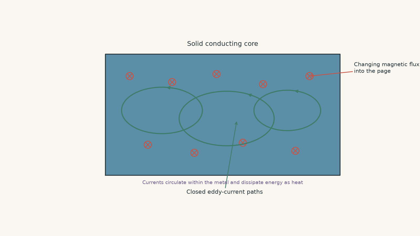
The name is useful. Think of little whirlpools forming in moving water. An eddy current also circulates locally instead of travelling from a useful input terminal to a useful output terminal.
The analogy stops there. Real eddy currents aren’t a few neat circular wires hidden inside the core. Current is distributed continuously through the conducting material.
02Why eddy currents waste energy
Suppose one possible current path through the core has resistance \(R\). Once an emf is induced around it, the current is approximately
\[
I=\frac{\epsilon}{R}
\]
where \(I\) is current in amperes, \(\text{A}\), and \(R\) is resistance in ohms, \(\Omega\).
That current heats the metal through resistance:
\[
P=I^2R
\]
where \(P\) is power converted to thermal energy in watts, \(\text{W}\).
Combining the two equations gives
\[
P=\frac{\epsilon^2}{R}
\]
This second form is particularly useful for understanding transformer design.
The eddy current also produces its own magnetic field. By Lenz’s law, that field opposes the change in magnetic flux that produced the current. The primary supply must provide additional energy to maintain transformer operation, and some of that electrical energy ends up as unwanted thermal energy in the core.
So the energy path is:
primary electrical energy \(\rightarrow\) induced eddy currents in the core \(\rightarrow\) thermal energy.
This is a core loss. It can occur even when the secondary is supplying no load.
Worked example: Heating from one representative eddy-current path
A changing magnetic field passes perpendicularly through a representative conducting path of area \(4.0\times10^{-4}\text{ m}^2\) inside a transformer core. The magnetic field changes from \(+0.80\text{ T}\) to \(-0.80\text{ T}\) in \(4.0\text{ ms}\). The resistance of the path is \(0.040\ \Omega\).
Calculate the magnitude of the induced emf, current, and power dissipated during this interval.
Step 1
\[
|\Delta B|=|-0.80-(+0.80)|=1.60\text{ T}
\]
The time interval is
\[
\Delta t=4.0\text{ ms}=4.0\times10^{-3}\text{ s}
\]
Step 2
\[
\left|\frac{\Delta B}{\Delta t}\right|
=\frac{1.60}{4.0\times10^{-3}}
=400\text{ T s}^{-1}
\]
Step 3
\[
|\epsilon|
=A\left|\frac{\Delta B}{\Delta t}\right|
=(4.0\times10^{-4})(400)
=0.16\text{ V}
\]
Step 4
\[
I=\frac{\epsilon}{R}
=\frac{0.16}{0.040}
=4.0\text{ A}
\]
Step 5
\[
P=I^2R
=(4.0)^2(0.040)
=0.64\text{ W}
\]
This \(0.64\text{ W}\) is for our simplified representative path during that interval, not the total loss of a real transformer core. A real core contains distributed eddy currents rather than one isolated loop.
The important result is the mechanism: changing flux produces an emf, the conducting core permits current, and resistance turns electrical energy into heat.
03Why a solid core is especially bad
Picture an eddy current trying to run a lap around a large region of solid metal.
A large path can enclose a relatively large changing magnetic flux. From Faraday’s law, more changing flux means a larger induced emf.
The solid core also gives the current a substantial conducting cross-section. That can make the resistance of the path quite low.
So a solid conducting core gives eddy currents two advantages you do not want them to have:
- relatively large flux-linking loops, which can produce larger induced emfs, and
- low-resistance conducting paths, which permit larger currents.
Transformer designers therefore break the core into thin sheets called laminations.
04What laminations actually change
A laminated transformer core is made from many thin sheets of magnetic material. Neighbouring sheets are electrically insulated from each other.
The insulation is the crucial part. Simply slicing the core and then electrically reconnecting all the slices would not achieve the same result.
The sheets are arranged so that the transformer’s main magnetic flux can travel mostly along the magnetic material, while large eddy-current loops would have to cross electrically insulating boundaries.
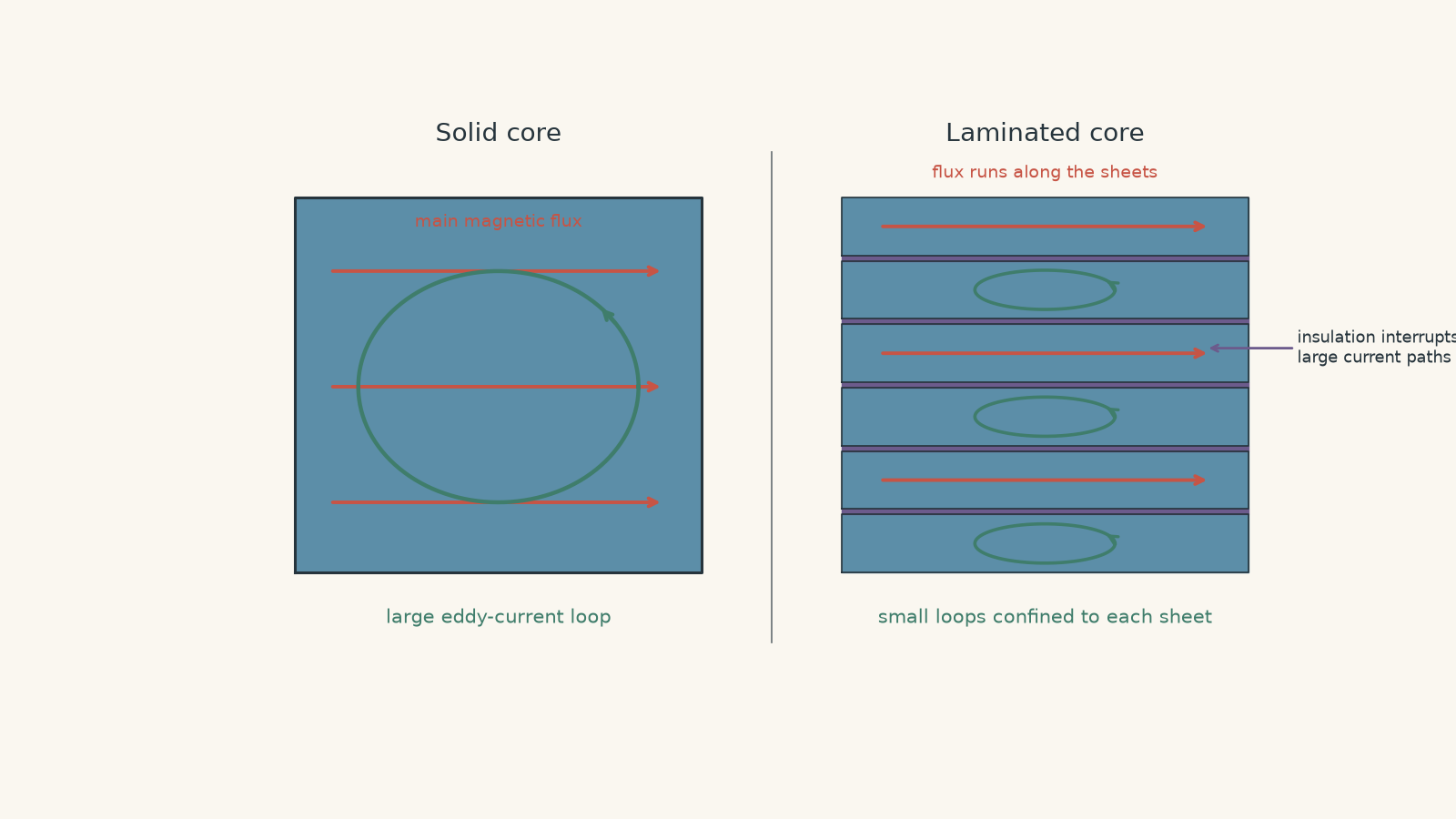
A slightly silly way to picture it is an indoor go-kart track. A solid core gives the current a huge open floor on which to complete a wide lap. Laminations add insulating walls. A current trying to make the same wide lap runs into a barrier, so only much smaller local loops remain.
The analogy breaks because electric current is not choosing a route like a driver. The induced electric field exists throughout the conducting material. The useful point is simply that insulation interrupts possible closed conducting paths.
Laminations reduce eddy-current loss in two linked ways.
1. They reduce the effective area of many current loops
For a path with perpendicular magnetic field,
\[
|\epsilon|=A\left|\frac{\Delta B}{\Delta t}\right|
\]
A smaller effective loop area \(A\) links less changing magnetic flux, so the induced emf is smaller.
2. They increase the resistance of possible current paths
A thin sheet provides a much smaller conducting thickness than one solid block.
For a conductor,
\[
R=\rho\frac{L}{A_c}
\]
where:
- \(\rho\) is electrical resistivity in ohm metres, \(\Omega\text{ m}\),
- \(L\) is the current-path length in metres, and
- \(A_c\) is the conducting cross-sectional area in square metres.
Reducing the available conducting cross-section raises the resistance of many eddy-current paths.
The combination is powerful because
\[
P=\frac{\epsilon^2}{R}
\]
Laminations can reduce \(\epsilon\) while increasing \(R\).
Worked example: Why the reduction can be much larger than expected
Consider a simplified representative path in a solid transformer core. It encloses an area of \(6.0\times10^{-4}\text{ m}^2\), the magnetic field changes at \(300\text{ T s}^{-1}\), and the path resistance is \(0.030\ \Omega\).
After lamination, suppose the effective loop area is reduced to one-eighth of its original value and the path resistance becomes four times larger.
Compare the power dissipated in the two representative paths.
Step 1
\[
\epsilon_s
=A_s\frac{\Delta B}{\Delta t}
=(6.0\times10^{-4})(300)
=0.180\text{ V}
\]
Step 2
\[
P_s=\frac{\epsilon_s^2}{R_s}
=\frac{(0.180)^2}{0.030}
=1.08\text{ W}
\]
Step 3
\[
A_l=\frac{6.0\times10^{-4}}{8}
=7.5\times10^{-5}\text{ m}^2
\]
\[
R_l=4(0.030)=0.120\ \Omega
\]
Step 4
\[
\epsilon_l
=(7.5\times10^{-5})(300)
=0.0225\text{ V}
\]
Step 5
\[
P_l=\frac{(0.0225)^2}{0.120}
=4.22\times10^{-3}\text{ W}
\]
Step 6
\[
\frac{P_s}{P_l}
=\frac{1.08}{4.22\times10^{-3}}
\approx256
\]
In this simplified model, the representative eddy-current loss is reduced by a factor of about \(256\).
That large reduction makes sense. Reducing the loop area to one-eighth reduces the emf to one-eighth. Since power depends on \(\epsilon^2\), that alone produces a factor of \(64\). Increasing resistance by another factor of four gives the total factor of \(256\).
05The \(P=I^2R\) trap
A common argument goes like this:
Laminations increase resistance. But \(P=I^2R\), so higher resistance should create more heating.
The equation is correct. The conclusion is not.
It quietly assumes that the current stays constant.
Here, the current does not stay constant. It is produced by the induced emf:
\[
I=\frac{\epsilon}{R}
\]
If the same induced emf acted around a path while its resistance increased, the current would fall. Substituting \(I=\epsilon/R\) into \(P=I^2R\) gives
\[
P=\frac{\epsilon^2}{R}
\]
So, for a given induced emf, increasing resistance decreases the power dissipated.
Laminations go further: they generally reduce the relevant induced emf as well by restricting the size of current loops.
Whenever two correct equations seem to predict opposite behaviour, check which quantities are actually being held constant. That habit matters well beyond eddy currents.
06Thinner laminations are more effective
For a simple laminated-core model, classical eddy-current power loss per unit volume follows an approximate relationship of the form
\[
P_e\propto\frac{B_{\max}^2f^2t^2}{\rho}
\]
where:
- \(P_e\) represents eddy-current power loss per unit volume,
- \(B_{\max}\) is the maximum magnetic flux density,
- \(f\) is the alternating-field frequency,
- \(t\) is lamination thickness, and
- \(\rho\) is the electrical resistivity of the core material.
This is not a general HSC formula to memorise. It is a useful model for seeing the trends.
It predicts that eddy-current loss becomes larger when:
| Change | Approximate effect on eddy-current loss |
|---|---|
| \(B_{\max}\) increases | increases roughly with \(B_{\max}^2\) |
| frequency \(f\) increases while \(B_{\max}\) stays fixed | increases roughly with \(f^2\) |
| lamination thickness \(t\) increases | increases roughly with \(t^2\) |
| resistivity \(\rho\) increases | decreases |
The phrase “while the other quantities stay fixed” matters. Later, you will see why changing the frequency does not always leave \(B_{\max}\) fixed.
07What laminations do not do
Laminations reduce eddy currents. They do not make every transformer loss disappear.
First, small eddy currents can still circulate inside each individual lamination. The aim is to make these currents much smaller, not magically zero.
Second, laminations do not eliminate hysteresis loss. Hysteresis is caused by repeated changes in the magnetic state of the core material. It is a different core-loss mechanism.
Third, the insulation is not meant to block the transformer’s main magnetic flux. The laminations are oriented so that flux can travel mainly along the magnetic sheets while the insulation interrupts troublesome electrical current paths.
That last point is easy to miss. “Insulate the core” is not a complete design rule. The orientation of the insulation matters.
08A compact way to reason about any eddy-current problem
When you meet an unfamiliar transformer question, track five things:
- Is the magnetic flux changing?
- What conducting closed paths are available?
- How much changing flux can each path enclose?
- What resistance does each path have?
- Where does the electrical energy ultimately go?
If there is changing flux, a large closed conducting path, and low resistance, expect significant eddy currents.
If insulated laminations interrupt those paths, expect smaller currents and less heating.
09Questions and solutions
Question 1
A transformer uses an alternating current in its primary coil and has a conducting iron core.
Explain why eddy currents form in the core, why they reduce transformer efficiency, and how laminating the core reduces this loss.
Solution 1
Eddy currents form because the changing magnetic flux in the transformer induces emfs around closed conducting paths inside the core. These currents dissipate energy as heat, while laminations restrict the current paths and greatly reduce the loss.
The alternating primary current produces changing magnetic flux. By Faraday’s law, a changing flux through a conducting loop induces an emf. Because a solid metal core contains many possible closed conducting paths, circulating currents can form inside it.
These currents cause resistive heating:
\[
P=I^2R
\]
The thermal energy comes from the electrical energy supplied to the transformer, so less of the input energy is available for useful transfer to the secondary circuit.
A laminated core consists of thin magnetic sheets separated electrically from neighbouring sheets. The insulation prevents large eddy-current loops from passing freely through the whole core.
The remaining loops generally enclose less changing flux, so their induced emfs are smaller, and their conducting paths have greater resistance. Both effects reduce eddy-current heating.
The tempting misconception is that the laminations stop the magnetic flux. They are designed mainly to interrupt electrical current paths while still allowing the transformer’s main magnetic flux to travel through the magnetic core.
Question 2
A representative eddy-current path has an RMS induced emf of \(0.090\text{ V}\) when a transformer operates at \(50\text{ Hz}\). The resistance of the path is \(0.015\ \Omega\).
The frequency is increased to \(60\text{ Hz}\), while the maximum magnetic flux density, geometry, and resistance are assumed to remain unchanged.
Assuming induced emf is proportional to frequency under these conditions:
a. calculate the power dissipated at \(50\text{ Hz}\),
b. calculate the power dissipated at \(60\text{ Hz}\), and
c. determine the percentage increase in power.
Solution 2
The power rises from \(0.54\text{ W}\) to approximately \(0.78\text{ W}\), an increase of \(44\%\).
The important constraint is that the maximum magnetic flux density is being held fixed. That means increasing frequency makes the flux change more rapidly, increasing the induced emf.
At \(50\text{ Hz}\),
\[
P_{50}
=\frac{\epsilon_{50}^2}{R}
=\frac{(0.090)^2}{0.015}
=0.54\text{ W}
\]
For the new emf,
\[
\frac{\epsilon_{60}}{\epsilon_{50}}
=\frac{60}{50}
\]
so
\[
\epsilon_{60}
=0.090\left(\frac{60}{50}\right)
=0.108\text{ V}
\]
Therefore,
\[
P_{60}
=\frac{(0.108)^2}{0.015}
=0.7776\text{ W}
\approx0.78\text{ W}
\]
The percentage increase is
\[
\frac{0.7776-0.54}{0.54}\times100\%
=44\%
\]
A tempting prediction is that a \(20\%\) increase in frequency should produce a \(20\%\) increase in heating. That misses the square in
\[
P=\frac{\epsilon^2}{R}
\]
When \(B_{\max}\) remains fixed, \(\epsilon\propto f\), so this simplified model gives \(P\propto f^2\). Thus
\[
\left(\frac{60}{50}\right)^2=1.44
\]
which agrees with the \(44\%\) increase.
Question 3
For a particular transformer core, use the approximate model
\[
P_e\propto\frac{B_{\max}^2f^2t^2}{\rho}
\]
Two possible redesigns are considered. \(B_{\max}\) and \(f\) remain unchanged.
- Design A reduces lamination thickness from \(0.50\text{ mm}\) to \(0.30\text{ mm}\), with unchanged resistivity.
- Design B keeps the \(0.50\text{ mm}\) laminations but uses a material with twice the original electrical resistivity.
Compare the new eddy-current loss for each design with the original. Can you also conclude from this information that the design with lower eddy-current loss must produce a lower secondary voltage?
Solution 3
Design A reduces the modelled eddy-current loss to \(36\%\) of the original, while Design B reduces it to \(50\%\). You cannot conclude that the lower-loss design must produce a lower secondary voltage.
For Design A, only the lamination thickness changes:
\[
\frac{P_A}{P_0}
=\left(\frac{0.30}{0.50}\right)^2
=(0.60)^2
=0.36
\]
So Design A leaves \(36\%\) of the original eddy-current loss, corresponding to a \(64\%\) reduction.
For Design B, the resistivity doubles:
\[
\frac{P_B}{P_0}
=\frac{\rho_0}{2\rho_0}
=\frac12
\]
So Design B leaves \(50\%\) of the original eddy-current loss, corresponding to a \(50\%\) reduction.
The tempting next step is to say that a stronger reduction in core loss must also reduce the transformer’s output voltage. That mixes two different effects.
Eddy-current loss concerns unwanted energy dissipation in the core. The secondary induced emf depends primarily on how rapidly magnetic flux links the secondary winding. If the flux waveform and turns remain unchanged, reducing eddy-current heating does not by itself require a smaller secondary emf.
In a real transformer, losses and flux can interact, so the full behaviour can be more complicated. But the supplied loss model alone does not justify a conclusion about secondary voltage.
Question 4
A transformer is operating with a sinusoidal supply. For fixed primary turns and core cross-sectional area, assume
\[
V_p\propto fB_{\max}
\]
and approximate eddy-current loss by
\[
P_e\propto f^2B_{\max}^2
\]
The transformer is changed from \(50\text{ Hz}\) operation to \(100\text{ Hz}\), but the primary RMS voltage remains unchanged.
A student argues:
Doubling frequency must quadruple the eddy-current loss because \(P_e\propto f^2\).
Under the stated assumptions, determine what happens to \(B_{\max}\) and to the eddy-current loss. Explain the flaw in the student’s argument.
Solution 4
Under the stated model, \(B_{\max}\) halves and the eddy-current loss remains approximately unchanged.
The student’s \(f^2\) argument would be correct only if \(B_{\max}\) were held constant. It is not constant here because the primary voltage is fixed.
From
\[
V_p\propto fB_{\max}
\]
and constant \(V_p\),
\[
f_1B_1=f_2B_2
\]
Therefore,
\[
50B_1=100B_2
\]
so
\[
B_2=\frac12B_1
\]
Now compare the eddy-current losses:
\[
\frac{P_2}{P_1}
=
\left(\frac{f_2}{f_1}\right)^2
\left(\frac{B_2}{B_1}\right)^2
\]
Substituting,
\[
\frac{P_2}{P_1}
=
\left(\frac{100}{50}\right)^2
\left(\frac12\right)^2
=4\times\frac14
=1
\]
So
\[
P_2=P_1
\]
within the supplied model.
The tempting route is to notice \(f^2\) and stop. The missing interaction is that frequency also affects the flux density required to produce the same primary induced emf.
Doubling \(f\) gives one factor of four increase in the loss expression, but halving \(B_{\max}\) gives a factor of four decrease. They cancel.
This does not mean every transformer loss stays unchanged when frequency doubles. Hysteresis, winding effects, leakage behaviour, material properties, and other real effects may change. The conclusion applies only to the stated eddy-current model.
Question 5
Consider a small region of a transformer core in which the main alternating magnetic flux points locally from left to right.
Two cores use identical thin, electrically insulated steel sheets.
In Core X, each sheet lies in the left-right and up-down directions, and the sheets are stacked from front to back. The main magnetic flux therefore runs mainly within each steel sheet.
In Core Y, each sheet lies in the up-down and front-back directions, and the sheets are stacked from left to right. The main magnetic flux therefore has to cross successive sheet boundaries.
A student says the two cores should suppress eddy currents equally well because both use sheets of the same thickness and the same insulation.
Determine which arrangement is better suited to a transformer. Your explanation must consider both the possible eddy-current paths and the path of the main magnetic flux.

Solution 5
Core X is the better arrangement: its insulation interrupts large eddy-current loops while allowing the main transformer flux to travel mainly through magnetic steel. Core Y places the sheets in the wrong orientation for both jobs.
Start with the main magnetic field, which points left to right.
An eddy current induced by that changing field tends to circulate around the field direction. Locally, that means a possible current loop lies in a plane containing the up-down and front-back directions.
In Core X, the laminations are stacked front to back. A large current loop in the up-down/front-back plane would therefore have to cross from one sheet into neighbouring sheets.
But the sheets are electrically insulated from each other.
That breaks the large conducting loop. Only much smaller loops can remain within an individual thin sheet. Their effective flux-linking area is reduced, and their resistance is greater.
Now follow the main magnetic flux. It points left to right, which lies within the plane of each sheet in Core X. The flux can therefore travel mainly through magnetic steel rather than repeatedly crossing insulating boundaries.
Core Y reverses those advantages.
Its broad sheet lies in the same up-down/front-back plane in which an eddy current can circulate around the left-right magnetic field. A current can therefore form a relatively large loop while remaining inside one conducting sheet. The insulation between neighbouring sheets does much less to interrupt that particular loop.
At the same time, the desired magnetic flux travels left to right, so in Core Y it must repeatedly cross the boundaries between the sheets rather than remaining mainly within the magnetic material.
The student’s reasoning focuses only on sheet thickness. The missing constraint is geometry. Lamination works because the insulating boundaries must be placed so that they interrupt unwanted electrical current paths without unnecessarily interrupting the desired magnetic flux path.
That is the deeper design rule: laminations are not merely thin pieces of metal. Their orientation is part of how they work.
Once eddy-current loss is separated from useful induction, you can make sense of the gap between an ideal transformer and a real one. The ideal transformer voltage and turns ratio describes the intended voltage transformation; eddy currents explain one reason a real transformer also draws energy that never reaches the load.