
Free-Body Diagrams: How to Draw Forces Correctly in HSC Physics
Learn how to isolate an object, identify the forces acting on it, choose correct force directions, and avoid common free-body diagram mistakes.
A box is sliding to the right across a rough floor. Which way should the arrows point?
Most students will draw a rightward arrow because the box is moving right. That feels sensible, but it can be completely wrong. A free-body diagram does not show the direction of motion. It shows the forces acting on one chosen object.
That difference is the whole game.
Suppose the box is moving right but slowing down. Predict the horizontal direction of the net force before reading on.
It must be to the left. An object can move right while the net force points left. Velocity tells you how the object is moving. Net force tells you how its velocity is changing.
A good free-body diagram separates those ideas before the algebra begins.
01What a free-body diagram is actually doing
Imagine taking one object out of a complicated situation and putting it alone under a spotlight. You ignore the rest of the scene for a moment and ask:
What other objects are interacting with this object right now?
Each interaction can produce a force.
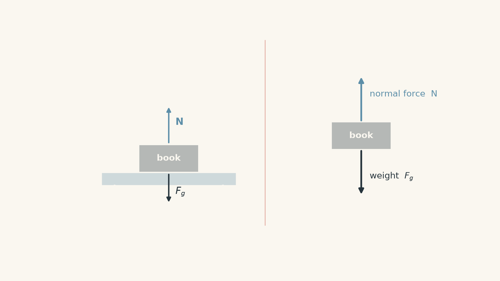
For a book resting on a desk:
- Earth pulls the book downward through gravity.
- The desk pushes the book upward through contact.
Those are the forces on the book.
The book also pulls Earth upward gravitationally and pushes the desk downward. Those forces are real, but they act on Earth and the desk, not on the book. They therefore do not belong on the book’s free-body diagram.
This is why the word free matters. We mentally free one object from its surroundings, then replace each relevant interaction with a force arrow.
02The rule that prevents most mistakes
Before drawing any arrows, complete this sentence:
“I am drawing the forces acting on ______.”
That blank is your chosen system.
If the system is a sled, every arrow must represent a force acting on the sled.
If the system is a person standing on the sled, the arrows will be different.
If the system is the person and sled together, forces between the person and sled become internal to the system and usually disappear from the diagram.
A slightly silly way to think about it is a relationship audit. You’re not asking, “Who exists in this story?” You’re asking, “Who is actually interacting with my chosen object?” The analogy breaks because forces follow physical interactions, not social drama, but the filtering idea is useful.
03A reliable four-step method
Step 1: Isolate the object
Replace the object with a simple box or dot. You usually do not need to draw its actual shape.
The free-body diagram is not meant to be a picture of the scene. It is a force inventory.
Step 2: List the interactions
Ask what can exert a force on the object.
Common HSC Physics interactions include:
| Interaction | Typical force | Direction |
|---|---|---|
| Earth and object | Weight \(F_g\) or \(mg\) | Vertically downward |
| Surface and object | Normal force \(N\) | Perpendicular to the surface |
| Rough surfaces | Friction \(f\) | Along the surface, opposing relative sliding or the tendency to slide |
| Rope or cable | Tension \(T\) | Along the rope, pulling away from the object |
| Person or machine pushing/pulling | Applied force \(F\) | In the direction of the push or pull |
| Fluid such as air or water | Drag | Opposes motion relative to the fluid |
| Spring and object | Spring force | Along the spring, towards its equilibrium position |
This table is a starting point, not a list of forces you automatically add. A force belongs in the diagram only if the corresponding interaction exists.
Step 3: Draw each force in its physical direction
An arrow’s direction comes from the interaction, not from where you want the object to move.
For example, the normal force is perpendicular to the contact surface. On a horizontal floor, that happens to mean vertically upward.
On a ramp, the normal force is tilted.
This is one reason the common shortcut \(N = mg\) is dangerous. Sometimes it is true. It is not the definition of normal force.
Step 4: Only then apply Newton’s laws
Once the diagram is correct, you can write
\[ \sum \vec{F} = m\vec{a} \]
where \(\sum \vec{F}\) is the vector sum of all external forces on the chosen object, \(m\) is its mass in kilograms, and \(\vec{a}\) is its acceleration in metres per second squared.
The free-body diagram comes before this equation because it tells you which forces belong in the sum.
04Motion is not a force
Consider a hockey puck sliding to the right across rough ice after it has been struck. The stick is no longer touching it.
What horizontal forces act on the puck?
A tempting answer is:
- friction to the left
- a “motion force” to the right
The second force does not exist.
Once the stick loses contact with the puck, the stick no longer exerts a contact force on it. The puck can keep moving to the right because an object does not require a forward force to maintain velocity.
If friction is the only horizontal force, then the net force points left. The puck therefore accelerates left, meaning its rightward velocity decreases.
This is Newton’s first and second laws working together.
A force is connected to an interaction, not automatically to motion.
05Weight and normal force are not a Newton’s third law pair
A book rests on a horizontal table. Its weight is downward and the normal force from the table is upward.
The two forces may have equal magnitudes. Does that make them a Newton’s third law pair?
No.
They both act on the same object, the book.
Newton’s third law pairs always act on different objects.
The gravitational third law pair is:
- Earth pulls the book downward.
- The book pulls Earth upward.
The contact third law pair is:
- the table pushes the book upward,
- the book pushes the table downward.
Only the forces acting on the book belong on the book’s free-body diagram.
06The normal force is not automatically equal to weight
For an object resting on a horizontal table with no other vertical forces, vertical acceleration is zero. Therefore,
\[ \sum F_y = 0 \]
so
\[ N - mg = 0 \]
and therefore
\[ N = mg. \]
Notice what happened. We derived \(N = mg\) from the circumstances.
We did not start with it as a universal rule.
If you push downward on the object, \(N\) can become greater than \(mg\). If you pull upward at an angle, \(N\) can become smaller than \(mg\). On an inclined surface, the normal force is not even opposite the entire weight force.
07Friction does not simply mean “opposite the velocity”
Friction acts to oppose relative sliding, or the tendency for relative sliding, between surfaces.
For a block sliding right across a stationary floor, friction on the block points left. Easy.
But imagine a box sitting on the floor of a truck that accelerates forwards. If the box does not slip, static friction on the box points forwards.
That might look strange because the box is also moving forwards. But without friction, the truck floor would accelerate ahead underneath the box. Static friction acts forwards to prevent that relative slipping.
So “friction always points opposite motion” is not reliable.
A better question is:
Which way would the surfaces slide relative to each other if friction were absent?
Friction opposes that relative sliding or tendency.
08Worked example: pulling a box across a floor
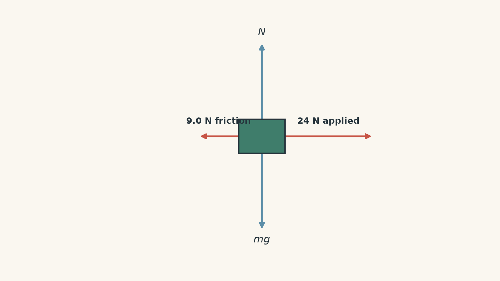
A \(6.0\text{ kg}\) box is pulled horizontally to the right with a force of \(24\text{ N}\). Friction acts on the box with a magnitude of \(9.0\text{ N}\). Draw the free-body diagram and determine the box’s acceleration.
Step 1
Earth pulls the box downward, the floor pushes upward, the pulling agent exerts \(24\text{ N}\) to the right, and the floor exerts friction to the left.
The four forces are therefore:
- weight \(mg\), downward,
- normal force \(N\), upward,
- applied force \(24\text{ N}\), right,
- friction \(9.0\text{ N}\), left.
Step 2
The pull is horizontal, and the box has no vertical acceleration, so
\[ N - mg = 0. \]
Its weight is
\[ mg = 6.0 \times 9.8 = 58.8\text{ N}. \]
Therefore,
\[ N = 58.8\text{ N}. \]
Step 3
Take right as positive.
\[ \sum F_x = 24 - 9.0 = 15\text{ N}. \]
Step 4
\[ \begin{aligned} \sum F_x &= ma \\ 15 &= 6.0a \\ a &= 2.5\text{ m s}^{-2} \end{aligned} \]
The box accelerates at \(2.5\text{ m s}^{-2}\) to the right.
The important point is that the acceleration follows from the net force, not simply from the fact that the box is being pulled right.
09Forces on an inclined plane
A ramp makes free-body diagrams more interesting because “up” and “perpendicular to the surface” are no longer the same direction.
Consider a block on a slope.
Its weight \(mg\) still points vertically downward. Gravity does not rotate just because the floor does.
The normal force \(N\) points perpendicular to the slope.
If friction is present, friction points along the slope.
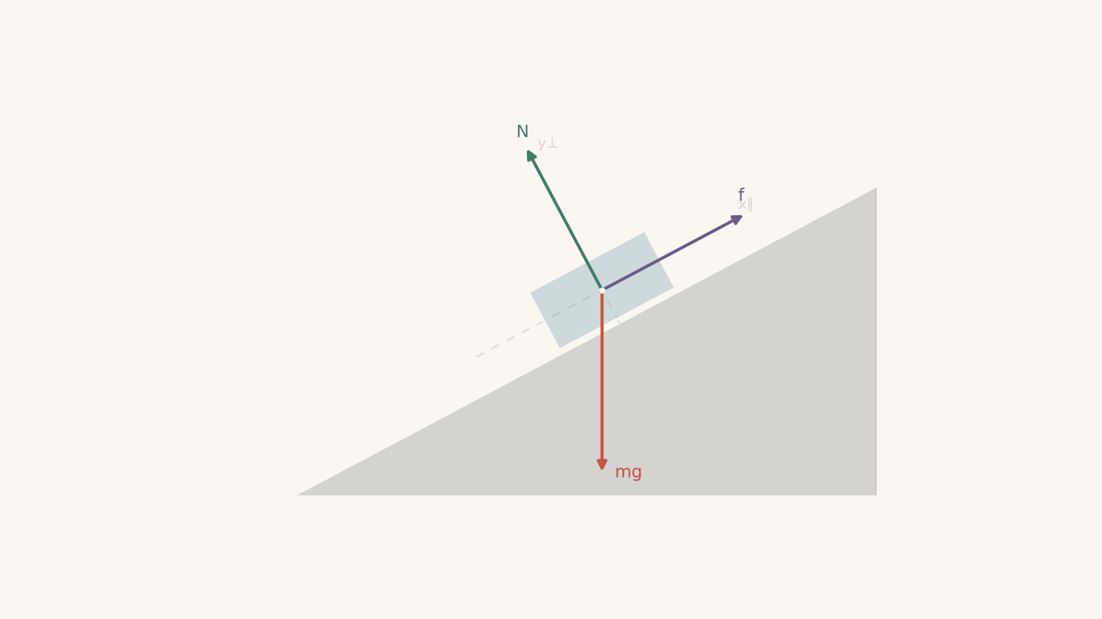
For calculations, it is usually convenient to choose axes parallel and perpendicular to the slope.
The weight can then be resolved into components:
\[ mg\sin\theta \]
parallel to the slope, and
\[ mg\cos\theta \]
perpendicular to the slope, where \(\theta\) is the angle of the slope above the horizontal.
These components are not extra forces. They are just the original weight force represented along useful coordinate directions.
That distinction matters. Your free-body diagram should not contain \(mg\), \(mg\sin\theta\), and \(mg\cos\theta\) as three separate gravitational forces.
10Worked example: a block sliding down a rough slope
An \(8.0\text{ kg}\) block slides down a \(30^\circ\) slope. Friction of \(12\text{ N}\) acts on the block. Draw the free-body diagram, find the normal force, and calculate the acceleration along the slope. Use \(g = 9.8\text{ m s}^{-2}\).
Step 1
The block has three forces acting on it:
- weight \(mg\), vertically downward,
- normal force \(N\), perpendicular to the slope,
- friction \(12\text{ N}\), up the slope because the block is sliding down it.
There is no separate “down-slope force”. The down-slope contribution comes from a component of the weight.
Step 2
\[ mg = 8.0 \times 9.8 = 78.4\text{ N}. \]
Step 3
The perpendicular component is
\[ mg\cos\theta. \]
The block does not accelerate through the surface, so the perpendicular net force is zero:
\[ \begin{aligned} N - mg\cos30^\circ &= 0 \\ N &= 78.4\cos30^\circ \\ N &\approx 67.9\text{ N}. \end{aligned} \]
Notice that \(N\) is less than \(mg\). This is exactly why \(N = mg\) cannot be treated as a general rule.
Step 4
The component pulling the block down the slope is
\[ \begin{aligned} mg\sin30^\circ &= 78.4\sin30^\circ \\ &= 39.2\text{ N}. \end{aligned} \]
Step 5
Take down the slope as positive.
\[ \sum F_{\parallel} = 39.2 - 12 = 27.2\text{ N}. \]
Step 6
\[ \begin{aligned} \sum F_{\parallel} &= ma \\ 27.2 &= 8.0a \\ a &= 3.4\text{ m s}^{-2}. \end{aligned} \]
The block accelerates down the slope at \(3.4\text{ m s}^{-2}\).
The free-body diagram made the calculation manageable because it separated the real forces first, then let us resolve one of them into useful components.
11Tension points along the rope
A rope can pull an object. An ideal flexible rope cannot push it.
So when a rope is attached to an object, the tension force on that object points:
- along the rope, and
- away from the object.
If a mass hangs from a vertical rope, tension points upward.
If a sled is pulled by a rope angled \(20^\circ\) above the horizontal, tension points \(20^\circ\) above the horizontal.
That angled tension has both horizontal and vertical components. Its upward component can reduce the normal force.
For a tension \(T\) at angle \(\theta\) above the horizontal,
\[ T_x = T\cos\theta \]
and
\[ T_y = T\sin\theta. \]
Again, \(T_x\) and \(T_y\) are components of one tension force, not two new physical interactions.
12When should you draw an arrow?
Before adding any force arrow, try this test:
“What object is exerting this force?”
If you cannot name one, be suspicious.
For weight, the answer is Earth.
For normal force, it is the contact surface.
For friction, it is the other surface.
For tension, it is the rope or cable.
A mysterious “force of motion”, “centripetal force” added on top of already identified inward forces, or “acceleration force” usually fails this test.
“Centripetal force” in particular is a description of the net inward force required for circular motion, not automatically an extra force. Depending on the situation, that inward net force might be provided by tension, gravity, friction, normal force, or a combination.
13A compact free-body diagram checklist
When you finish a diagram, check these points:
- Have I clearly chosen one object or system?
- Does every arrow represent a force on that system?
- Can I name the other object responsible for each force?
- Is weight vertical and downward?
- Is the normal force perpendicular to the contact surface?
- Does tension follow the rope?
- Have I worked out friction from relative sliding or its tendency, rather than blindly opposing velocity?
- Have I accidentally drawn velocity or acceleration as a force?
- Have I put both members of a Newton’s third law pair on one object?
- Have I mistaken force components for extra forces?
If those questions are under control, most later dynamics calculations become much cleaner.
14Questions and solutions
Question 1
A \(4.0\text{ kg}\) lamp hangs motionless from a single vertical cord. Draw the free-body diagram for the lamp and calculate the tension in the cord. Use \(g = 9.8\text{ m s}^{-2}\).
Solution 1
The lamp has two forces acting on it: weight downward and tension upward, and the tension is \(39.2\text{ N}\).
The lamp is motionless, so its acceleration is zero. Therefore the net vertical force must be zero.
Its weight is
\[ \begin{aligned} F_g &= mg \\ &= 4.0 \times 9.8 \\ &= 39.2\text{ N}. \end{aligned} \]
Taking upward as positive,
\[ \begin{aligned} \sum F_y &= 0 \\ T - mg &= 0 \\ T &= 39.2\text{ N}. \end{aligned} \]
The free-body diagram therefore contains an upward \(T\) arrow and a downward \(mg\) arrow of equal magnitude.
A common mistake is to add another downward force because the cord is “holding a weight”. The lamp’s weight already represents Earth’s gravitational force on it. The cord contributes only the upward tension force.
Question 2
A \(10\text{ kg}\) crate is pulled across a horizontal floor by a \(50\text{ N}\) force directed \(37^\circ\) above the horizontal. Friction on the crate is \(18\text{ N}\). Draw the free-body diagram, calculate the normal force, and determine the horizontal acceleration. Use \(g = 9.8\text{ m s}^{-2}\).
Solution 2
The normal force is approximately \(68\text{ N}\), and the crate accelerates horizontally at approximately \(2.2\text{ m s}^{-2}\) in the direction of the pull.
The forces on the crate are:
- weight \(mg\) downward,
- normal force \(N\) upward,
- the \(50\text{ N}\) pulling force at \(37^\circ\) above horizontal,
- friction \(18\text{ N}\) opposite the sliding.
First calculate the weight:
\[ mg = 10 \times 9.8 = 98\text{ N}. \]
The vertical component of the pulling force is
\[ \begin{aligned} F_y &= 50\sin37^\circ \\ &\approx 30.1\text{ N}. \end{aligned} \]
There is no vertical acceleration, so
\[ \begin{aligned} N + 30.1 - 98 &= 0 \\ N &\approx 67.9\text{ N}. \end{aligned} \]
The normal force is less than the weight because the rope is helping support the crate.
The horizontal component of the pull is
\[ \begin{aligned} F_x &= 50\cos37^\circ \\ &\approx 39.9\text{ N}. \end{aligned} \]
The horizontal net force is therefore
\[ \sum F_x = 39.9 - 18 = 21.9\text{ N}. \]
Using \(\sum F_x = ma\),
\[ \begin{aligned} 21.9 &= 10a \\ a &\approx 2.19\text{ m s}^{-2}. \end{aligned} \]
So the acceleration is approximately \(2.2\text{ m s}^{-2}\).
The tempting mistake is to use \(N = mg = 98\text{ N}\). That would ignore the upward component of the angled pull.
Question 3
A passenger stands on a bathroom scale inside a lift that is travelling upward but slowing down. A student says, “Because the lift is moving upward, the scale must push on the passenger with a force greater than their weight.”
Is the student correct? Draw the passenger’s free-body diagram and explain what the scale reading must be compared with the passenger’s weight.
Solution 3
The student is incorrect. The scale reading must be less than the passenger’s weight while the upward-moving lift slows down.
Only two significant forces act on the passenger:
- weight \(mg\) downward,
- normal force \(N\) from the scale upward.
The key is to separate velocity from acceleration.
The lift is travelling upward but slowing down, so its acceleration is downward. The passenger therefore also has a downward acceleration.
For the net force to point downward,
\[ mg > N. \]
Therefore,
\[ N < mg. \]
A bathroom scale measures the contact force, which is the normal force \(N\), rather than directly measuring \(mg\). Its reading is therefore lower than the passenger’s usual stationary reading.
The misconception comes from treating the direction of motion as the direction of net force. An object moving upward can have a downward net force if it is slowing down.
Question 4
A small block rests without slipping on the horizontal floor of a truck. The truck begins accelerating to the right.
One student draws the block’s free-body diagram with weight downward and normal force upward only. Another adds a friction force pointing left because “friction always opposes motion”.
Explain what is missing or incorrect in each diagram. State the direction of the friction force on the block.
Solution 4
Static friction on the block points to the right. The first diagram is missing this horizontal force, while the second student has chosen the wrong direction.
If there were no horizontal force on the block, Newton’s second law would give zero horizontal acceleration. The truck floor would accelerate to the right underneath it while the block tended to retain its original horizontal velocity.
Relative to the truck, the block would therefore tend to slip left.
Static friction opposes that relative slipping tendency, so the truck floor exerts friction on the block to the right.
That rightward friction is what gives the block its rightward acceleration:
\[ f_s = ma \]
provided the required friction does not exceed the maximum static friction available.
The important trap is the phrase “friction opposes motion”. The block is moving right and the friction force is also right. Friction opposes relative sliding, or the tendency to slide, between the contacting surfaces.
Question 5
A block slides down a rough incline at constant speed. A student draws three forces on it: weight \(mg\) vertically downward, normal force \(N\) perpendicular to the slope, and friction \(f\) up the slope. They then add a fourth force labelled “resultant force down the slope” because gravity has a component \(mg\sin\theta\) in that direction.
Identify the error. Then determine the relationship between the friction force and the component \(mg\sin\theta\).
Solution 5
The fourth arrow is incorrect. There is no additional resultant force to draw, and the friction magnitude must equal \(mg\sin\theta\).
A resultant force is not a separate interaction. It is the vector sum of the real forces already in the diagram.
Similarly, \(mg\sin\theta\) is not an extra force in addition to \(mg\). It is the component of the existing weight force parallel to the incline.
Because the block moves at constant speed, its acceleration is zero. Therefore the net force along the slope is zero.
Taking down the slope as positive,
\[ \begin{aligned} \sum F_{\parallel} &= 0 \\ mg\sin\theta - f &= 0. \end{aligned} \]
Hence,
\[ f = mg\sin\theta. \]
The forces balance along the slope even though the block is moving. Zero net force means zero acceleration, not zero velocity.
That is the deeper reason free-body diagrams matter: once you can separate actual interactions from motion, components, and resultants, Newton’s laws become a controlled accounting problem rather than a guessing exercise. The next useful step is learning to choose axes and resolve these forces efficiently in two-dimensional situations, especially inclined planes and circular motion.