
Maximum and Zero Motor-Effect Force in HSC Physics
Learn why motor-effect force is maximum at 90° and zero at 0° or 180°, with clear reasoning, worked examples, and challenging practice.
A straight wire carries a steady current through a uniform magnetic field. You keep the current, wire length, and field strength unchanged, but rotate the wire. In one orientation, the magnetic force is as large as it can possibly be. Rotate it again, and the force disappears completely.
Before reading on, predict the two orientations. Should the force be largest when the current runs along the magnetic field, or when it cuts across it?
The answer is slightly counter-intuitive the first time: the force is maximum when the current and magnetic field are perpendicular, and zero when they are parallel or anti-parallel.
That one idea explains the angular part of the motor effect.
01Picture the current cutting across the field
Imagine magnetic field lines running horizontally across the page. Now put a current-carrying wire into that field.
If the current also runs horizontally, it isn’t cutting across the field at all. In the HSC model, there is no motor-effect force on the wire.
Turn the wire until the current runs vertically. Now its direction is completely across the magnetic field. The force reaches its maximum possible magnitude.
At an angle in between, only part of the wire’s current direction is effectively across the field.
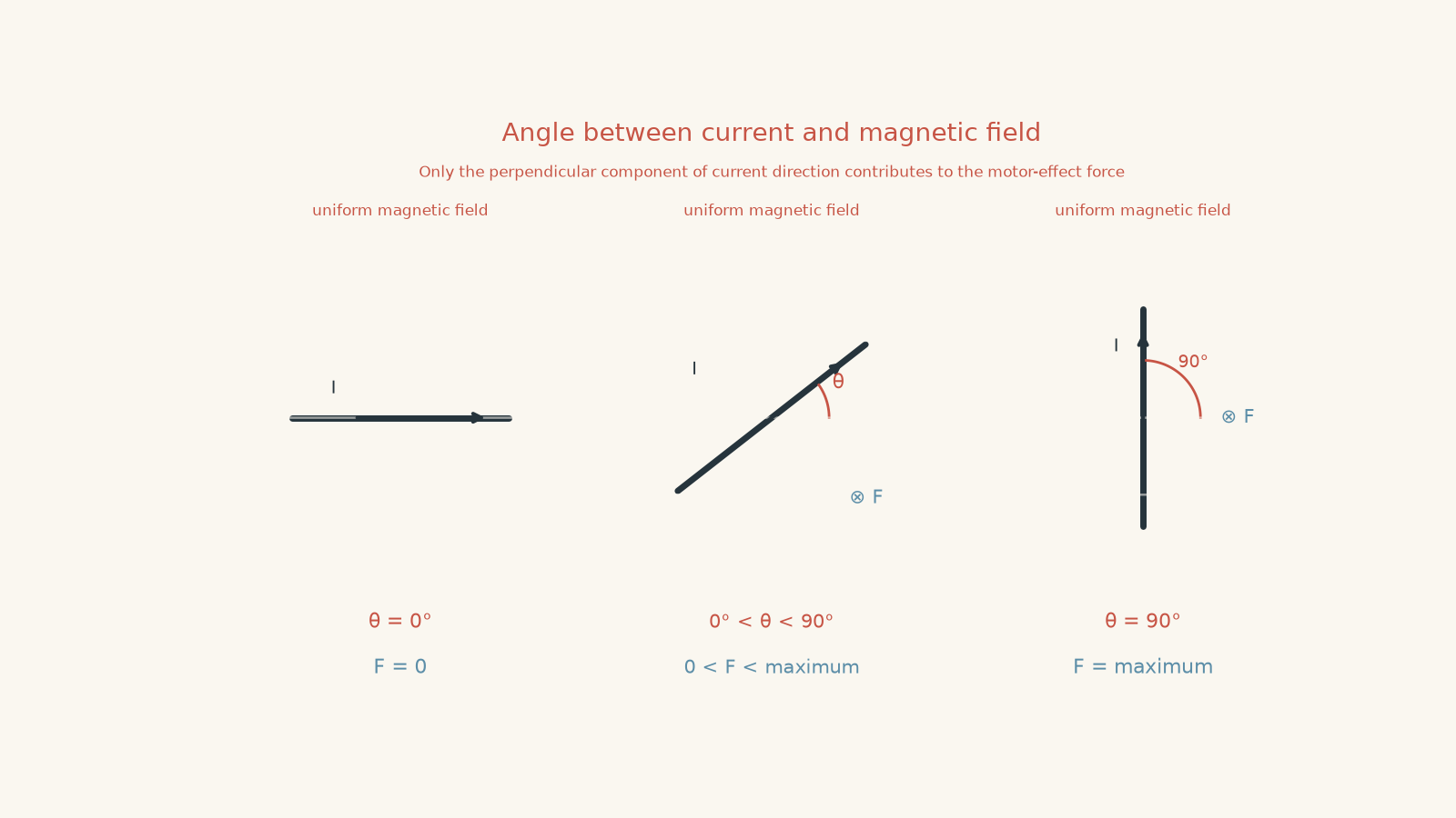
A slightly silly way to picture this is a crowded school corridor. Suppose everyone else is moving in one direction and you represent the current. Walking exactly with the crowd, or exactly against its direction, doesn’t give you a sideways component across the flow. Walking straight across the corridor gives the largest cross-flow interaction.
The analogy stops there. Magnetic forces aren’t caused by people bumping into each other. The useful part of the analogy is just the geometry: across matters; along does not.
02The equation tells us exactly how much the angle matters
For a straight current-carrying conductor in a uniform magnetic field,
\[
F = BIL\sin\theta
\]
where:
- \(F\) is the magnetic force on the conductor, in newtons (\(\text{N}\)),
- \(B\) is the magnetic field strength, in teslas (\(\text{T}\)),
- \(I\) is the conventional current, in amperes (\(\text{A}\)),
- \(L\) is the length of conductor inside the magnetic field, in metres (\(\text{m}\)), and
- \(\theta\) is the angle between the direction of conventional current and the magnetic field.
The important part for this guide is \(\sin\theta\).
Everything else can stay fixed while the force changes simply because the wire has been rotated.
| Angle \(\theta\) | \(\sin\theta\) | Force |
|---|---|---|
| \(0^\circ\) | 0 | Zero |
| \(30^\circ\) | 0.5 | Half the maximum |
| \(90^\circ\) | 1 | Maximum |
| \(150^\circ\) | 0.5 | Half the maximum |
| \(180^\circ\) | 0 | Zero |
Notice something important: \(30^\circ\) and \(150^\circ\) give the same force magnitude.
The formula cares about how strongly the current direction cuts across the magnetic field, not simply whether the angle looks large.
03Why is the force maximum at \(90^\circ\)?
The largest possible value of \(\sin\theta\) is 1.
That occurs when
\[
\theta = 90^\circ
\]
so the force becomes
\[
F_{\text{max}} = BIL.
\]
The whole current direction is perpendicular to the magnetic field. There is no component pointing along the field.
Another way to write the same idea is to think only about the perpendicular part of the conductor:
\[
L_\perp = L\sin\theta.
\]
Then
\[
F = BI L_\perp.
\]
At \(90^\circ\),
\[
L_\perp = L,
\]
so the entire relevant length contributes to the force.
This doesn’t mean the wire becomes physically longer. \(L_\perp\) is a geometric component: it tells us how much of the wire’s direction lies perpendicular to the field.
Worked example: Force on a wire at \(30^\circ\)
A \(0.25\text{ m}\) wire carries a current of \(3.0\text{ A}\) through a uniform magnetic field of \(0.40\text{ T}\). The current makes an angle of \(30^\circ\) with the magnetic field. Calculate the magnetic force on the wire and compare it with the maximum possible force.
Step 1
\[
F = BIL\sin\theta
\]
Step 2
\[
\begin{aligned}
F
&= (0.40)(3.0)(0.25)\sin30^\circ \\
&= (0.40)(3.0)(0.25)(0.5) \\
&= 0.15\text{ N}
\end{aligned}
\]
So the magnetic force is \(0.15\text{ N}\).
Step 3
\[
\begin{aligned}
F_{\text{max}}
&= BIL \\
&= (0.40)(3.0)(0.25) \\
&= 0.30\text{ N}
\end{aligned}
\]
The \(30^\circ\) force is exactly half the maximum because \(\sin30^\circ=0.5\).
The physical meaning is more useful than the arithmetic: at \(30^\circ\), the current has only half the perpendicular component it would have at \(90^\circ\).
04Why is the force zero at both \(0^\circ\) and \(180^\circ\)?
This is where a common mistake appears.
A student might think that \(180^\circ\) should give an enormous force because the current and magnetic field point in opposite directions. Opposite sounds like maximum conflict.
But magnetic force doesn’t work by measuring how much two arrows “disagree”. It depends on their perpendicular relationship.
At \(0^\circ\),
\[
\sin0^\circ=0.
\]
At \(180^\circ\),
\[
\sin180^\circ=0.
\]
Therefore,
\[
F=0
\]
in both cases.
The current is parallel to the field at \(0^\circ\) and anti-parallel to it at \(180^\circ\). Either way, there is no perpendicular component.
This also connects to the magnetic force on an individual moving charge:
\[
F=qvB\sin\theta,
\]
where \(q\) is the charge, \(v\) is its velocity, and \(\theta\) is the angle between its velocity and the magnetic field.
For the HSC conductor model, the motor effect is the combined result of magnetic forces associated with moving charge carriers. Motion along the field gives no magnetic force from that component; motion across the field does.
05The angle must be the correct angle
One of the easiest ways to lose marks here is to use an angle shown in the diagram without checking what that angle is actually between.
In
\[
F=BIL\sin\theta,
\]
\(\theta\) must be the angle between the conventional current direction and the magnetic field.
Suppose a diagram gives the angle between the wire and a line perpendicular to the magnetic field as \(20^\circ\). The current-field angle is then
\[
90^\circ-20^\circ=70^\circ,
\]
so you must use \(\sin70^\circ\), not \(\sin20^\circ\).
A good habit is to identify the current arrow and magnetic-field arrow first. Then find the angle between those two directions.
If you also need to determine which way the resulting force points, use the motor-effect direction rules. The angle determines the magnitude; the direction rule handles the direction.
Worked example: Inferring the wire’s angle from the force
A \(0.20\text{ m}\) conductor carries \(4.0\text{ A}\) in a \(0.80\text{ T}\) magnetic field. The magnetic force has magnitude \(0.52\text{ N}\). Find the possible angles between the current and the magnetic field.
Step 1
\[
F=BIL\sin\theta
\]
Step 2
\[
\sin\theta=\frac{F}{BIL}
\]
Step 3
\[
\begin{aligned}
\sin\theta
&=\frac{0.52}{(0.80)(4.0)(0.20)}\\
&=\frac{0.52}{0.64}\\
&=0.8125
\end{aligned}
\]
Step 4
\[
\theta=\sin^{-1}(0.8125)\approx54^\circ.
\]
But \(54^\circ\) is not the only possible angle between \(0^\circ\) and \(180^\circ\).
Because
\[
\sin54^\circ=\sin126^\circ,
\]
the second possible angle is approximately
\[
180^\circ-54^\circ=126^\circ.
\]
So the current may make an angle of approximately \(54^\circ\) or \(126^\circ\) with the magnetic field.
Both give the same force magnitude because they have the same perpendicular component. A diagram or information about the wire’s orientation would be needed to decide which angle applies physically.
06The quickest decision rule
For a current-carrying straight wire:
- current perpendicular to the magnetic field \(\rightarrow\) maximum force,
- current parallel to the magnetic field \(\rightarrow\) zero force,
- current anti-parallel to the magnetic field \(\rightarrow\) zero force,
- any angle in between \(\rightarrow\) use \(F=BIL\sin\theta\).
Don’t memorise \(90^\circ\) and \(0^\circ\) as disconnected facts. Remember the reason: only the component perpendicular to the magnetic field contributes to the motor-effect force.
That principle remains useful when the conductor is bent, when several conductor sections experience forces at once, and when you later consider the torque on a current-carrying coil.
07Questions and solutions
Question 1
A straight \(0.40\text{ m}\) conductor carries a current of \(2.5\text{ A}\) through a uniform \(0.60\text{ T}\) magnetic field.
The current is perpendicular to the magnetic field.
Calculate the magnetic force on the conductor.
Solution 1
The magnetic force is \(0.60\text{ N}\).
The governing equation is
\[
F=BIL\sin\theta.
\]
Because the current is perpendicular to the field,
\[
\theta=90^\circ
\]
and
\[
\sin90^\circ=1.
\]
Therefore,
\[
\begin{aligned}
F
&=(0.60)(2.5)(0.40)\sin90^\circ\\
&=(0.60)(2.5)(0.40)(1)\\
&=0.60\text{ N}.
\end{aligned}
\]
This is also the maximum possible force for these values of \(B\), \(I\), and \(L\).
A tempting mistake is to think that “perpendicular” means the force is zero because the directions do not line up. The opposite is true for magnetic force: the perpendicular arrangement produces the largest value of \(\sin\theta\).
Question 2
A \(0.50\text{ m}\) wire carries \(3.2\text{ A}\) through a \(0.75\text{ T}\) magnetic field. The force on the wire is \(0.78\text{ N}\).
Determine the possible angles between the current and magnetic field.
Solution 2
The possible angles are approximately \(41^\circ\) and \(139^\circ\).
Start with
\[
F=BIL\sin\theta.
\]
Rearranging,
\[
\sin\theta=\frac{F}{BIL}.
\]
Substitute the measurements:
\[
\begin{aligned}
\sin\theta
&=\frac{0.78}{(0.75)(3.2)(0.50)}\\
&=\frac{0.78}{1.20}\\
&=0.65.
\end{aligned}
\]
Therefore,
\[
\theta=\sin^{-1}(0.65)\approx40.5^\circ.
\]
So one possible angle is approximately \(41^\circ\).
However,
\[
\sin\theta=\sin(180^\circ-\theta),
\]
so the second solution is
\[
180^\circ-40.5^\circ=139.5^\circ.
\]
Hence the two possible angles are approximately \(41^\circ\) and \(139^\circ\).
The tempting route is to report only the calculator’s inverse-sine result. The missing constraint is that a physical angle between two directions may range from \(0^\circ\) to \(180^\circ\), and two angles in that range can have the same sine.
Question 3
A wire carrying a constant current is rotated from an angle of \(30^\circ\) to an angle of \(150^\circ\) relative to a uniform magnetic field.
A student says, “The angle has increased by \(120^\circ\), so the magnetic force must become much larger.”
Assuming \(B\), \(I\), and \(L\) stay constant:
- compare the force magnitudes before and after the rotation, and
- explain why the student’s reasoning fails.
Solution 3
The force magnitude is unchanged.
Initially,
\[
F_1=BIL\sin30^\circ.
\]
Since
\[
\sin30^\circ=0.5,
\]
\[
F_1=0.5BIL.
\]
After rotation,
\[
F_2=BIL\sin150^\circ.
\]
But
\[
\sin150^\circ=0.5,
\]
so
\[
F_2=0.5BIL.
\]
Therefore,
\[
F_1=F_2.
\]
The student’s reasoning fails because magnetic force is not proportional to the numerical size of the angle. It is proportional to the sine of the angle.
Both orientations have the same magnitude of perpendicular component relative to the magnetic field.
The tempting idea is that a “larger angle” must mean a larger force. That works only from \(0^\circ\) up to \(90^\circ\). Beyond \(90^\circ\), \(\sin\theta\) decreases again until the force reaches zero at \(180^\circ\).
Question 4
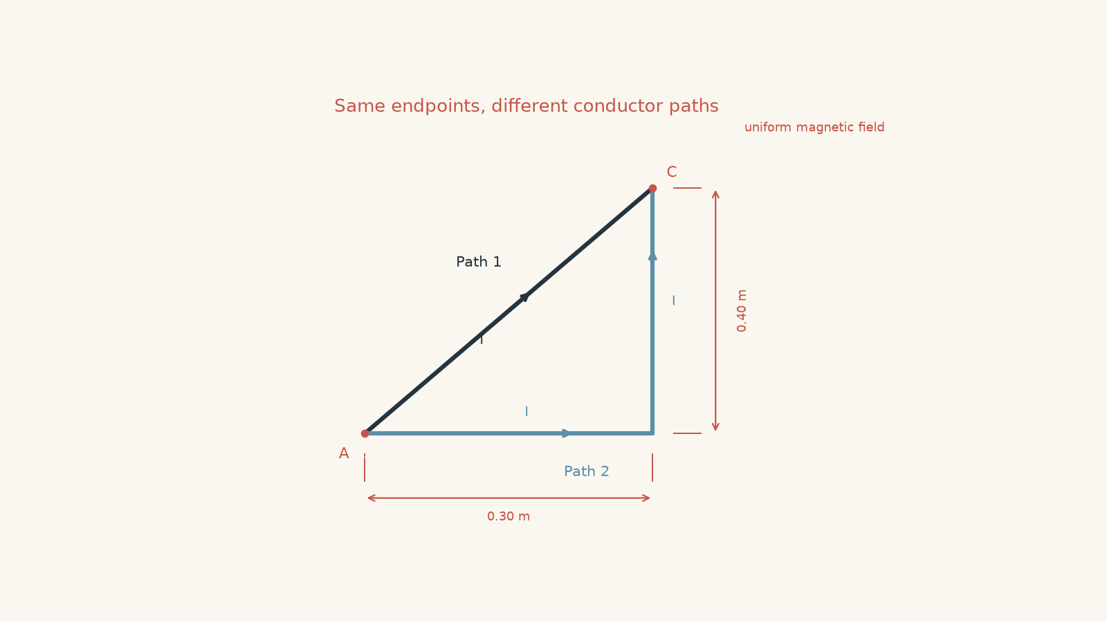
A wire carries current \(I\) from point A to point C through a uniform magnetic field \(B\) directed horizontally to the right.
Two possible wire shapes connect the same points.
- Path 1 is a straight diagonal wire from A to C. Its horizontal displacement is \(0.30\text{ m}\), and its vertical displacement is \(0.40\text{ m}\).
- Path 2 consists of a \(0.30\text{ m}\) horizontal section followed by a \(0.40\text{ m}\) vertical section.
The same current flows from A to C in both cases.
A student argues that Path 2 must experience a different total magnetic force because its two sections have different angles to the field.
Determine whether the total magnetic-force magnitude is different for the two paths. Express your answer in terms of \(B\) and \(I\).
Solution 4
Both paths experience the same total magnetic-force magnitude, \(0.40BI\).
For Path 2, consider the sections separately.
The horizontal section is parallel to the magnetic field, so
\[
F_{\text{horizontal}}
=BI(0.30)\sin0^\circ
=0.
\]
The vertical section is perpendicular to the field, so
\[
\begin{aligned}
F_{\text{vertical}}
&=BI(0.40)\sin90^\circ\\
&=0.40BI.
\end{aligned}
\]
Therefore, the total force magnitude on Path 2 is
\[
F_2=0.40BI.
\]
Now consider Path 1.
Its length is
\[
L=\sqrt{(0.30)^2+(0.40)^2}=0.50\text{ m}.
\]
If its angle to the horizontal magnetic field is \(\theta\), then
\[
\sin\theta=\frac{0.40}{0.50}=0.80.
\]
So
\[
\begin{aligned}
F_1
&=BIL\sin\theta\\
&=BI(0.50)(0.80)\\
&=0.40BI.
\end{aligned}
\]
Thus,
\[
F_1=F_2=0.40BI.
\]
The tempting route is to focus on the total wire length or on the fact that one path contains two different angles. The important constraint is the perpendicular displacement.
For Path 1, only the perpendicular component of its \(0.50\text{ m}\) length contributes, and that component is \(0.40\text{ m}\). For Path 2, the \(0.30\text{ m}\) parallel section contributes no force, while the entire \(0.40\text{ m}\) vertical section contributes.
This is a deeper version of the same rule: magnetic force depends on the conductor’s component perpendicular to the field.
Question 5
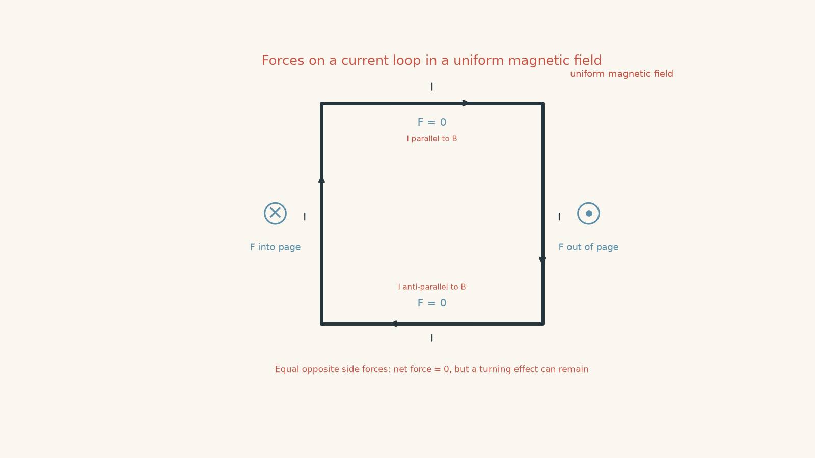
A square current-carrying loop is placed completely inside a uniform magnetic field. The magnetic field lies in the plane of the loop and is parallel to one pair of opposite sides.
A student reasons as follows:
“The two sides parallel to the field have zero force. The other two sides are perpendicular to the field, so each has maximum force. Those two forces are equal and opposite, so the total force is zero. Therefore the magnetic field cannot change the loop’s motion at all.”
Assess the student’s conclusion. Assume the loop is free to rotate.
Solution 5
The loop has zero net force, but the student’s final conclusion is incorrect: the magnetic field can still produce a non-zero torque and make the loop rotate.
First consider the two sides parallel to the field. For each,
\[
\theta=0^\circ
\]
or \(180^\circ\), so
\[
F=BIL\sin\theta=0.
\]
Now consider the other two sides. They are perpendicular to the magnetic field, so
\[
F=BIL
\]
on each side, the maximum possible force for that side.
Because current flows in opposite directions along these two opposite sides, their magnetic forces point in opposite directions. Their magnitudes are equal, so their vector sum is zero.
Therefore,
\[
F_{\text{net}}=0.
\]
Up to this point, the student’s argument is correct.
The crucial issue is that the two equal and opposite forces act at different positions on the loop. They form a couple. Instead of translating the loop’s centre of mass, they produce a turning effect.
So a zero net force does not imply zero mechanical effect.
The tempting conclusion treats all equal and opposite forces as though they acted at the same point. The missing constraint is their separation. Forces can cancel translationally while still producing a torque.
This is exactly why the angular behaviour of motor-effect forces leads naturally to the next idea: torque on a current-carrying coil. A motor does not need a net force pushing the whole coil across the room. It needs appropriately placed magnetic forces that produce rotation.