
Force Between Parallel Current-Carrying Wires: HSC Physics
Learn how to calculate force per unit length between parallel current-carrying wires and predict whether they attract or repel. Includes worked examples and challenging HSC-style questions.
Put two long wires side by side and run current through both. They aren’t touching, yet each wire can feel a sideways force. Now make a prediction: if the currents flow in the same direction, do the wires attract or repel?
It is tempting to borrow the rule for electric charges and guess that “same means repel”. That fails here. Parallel currents in the same direction attract. Parallel currents in opposite directions repel.
The useful question for HSC Physics is not just remembering that rule. It is understanding where the force comes from, how to calculate the force per unit length, and how to recover the direction if you forget the rule in an exam.
01One wire creates the field that pushes the other
Start with two long, straight, parallel wires separated by a distance \(d\).
Wire 1 carries current \(I_1\). Its current creates a circular magnetic field around the wire. At the position of wire 2, the magnetic field strength is
\[ B_1=\frac{\mu_0 I_1}{2\pi d} \]
where:
- \(B_1\) is the magnetic field produced by wire 1 at wire 2, in tesla (\(\text{T}\))
- \(\mu_0\) is the permeability of free space, \(4\pi\times10^{-7}\ \text{T m A}^{-1}\)
- \(I_1\) is the current in wire 1, in amperes (\(\text{A}\))
- \(d\) is the perpendicular distance between the wires, in metres (\(\text{m}\))
For HSC problems involving wires in air, using \(\mu_0\) is normally appropriate.
Wire 2 is now sitting inside that magnetic field. A current-carrying conductor in a magnetic field experiences the motor effect:
\[ F=BIL\sin\theta \]
Here, \(\theta\) is the angle between the current and the magnetic field.
There is an important trap here. The two wires are parallel, but the magnetic field at wire 2 is perpendicular to wire 2. Therefore \(\theta=90^\circ\), not \(0^\circ\).
So \(\sin90^\circ=1\), and the force on a length \(L\) of wire 2 is
\[ F=I_2LB_1 \]
This is a maximum motor-effect force. If that angle idea is shaky, it is worth revisiting maximum and zero motor-effect force before going further.
Substitute the field produced by wire 1:
\[ F=I_2L\left(\frac{\mu_0 I_1}{2\pi d}\right) \]
Therefore,
\[ F=\frac{\mu_0 I_1I_2L}{2\pi d} \]
and dividing by \(L\) gives the form you will use most often:
\[ \boxed{\frac{F}{L}=\frac{\mu_0 I_1I_2}{2\pi d}} \]
The units of \(F/L\) are newtons per metre (\(\text{N m}^{-1}\)).
This equation applies when the wires can be treated as long and straight, their separation is roughly constant, and end effects can be neglected.
02What the equation is telling you
Before doing any direction rules, look at the structure:
\[ \frac{F}{L}\propto\frac{I_1I_2}{d} \]
So:
- doubling either current doubles the force per unit length
- doubling both currents makes the force per unit length four times as large
- doubling the separation halves the force per unit length
- swapping \(I_1\) and \(I_2\) changes nothing about the magnitude
That last point matters. Even if the currents are different, each wire exerts the same magnitude force on the other over corresponding lengths. The forces point in opposite directions, consistent with Newton’s third law.
A useful shortcut follows from
\[ \frac{\mu_0}{2\pi} = \frac{4\pi\times10^{-7}}{2\pi} = 2.0\times10^{-7} \]
so in air,
\[ \frac{F}{L} = 2.0\times10^{-7}\frac{I_1I_2}{d} \]
with currents in amperes and \(d\) in metres.
03Why same-direction currents attract
Suppose two vertical wires sit side by side, and both currents flow upwards.
Use the right-hand grip rule on the left wire. Point your right thumb upwards with the current. Your curled fingers show the circular magnetic field. At the position of the right-hand wire, that field points into the page.
Now apply the motor-effect direction rule to the right-hand wire. Its current is upwards and the magnetic field is into the page, so its force points towards the left-hand wire.
Doing the same process for the other wire gives a force towards the right-hand wire.
The wires therefore attract.
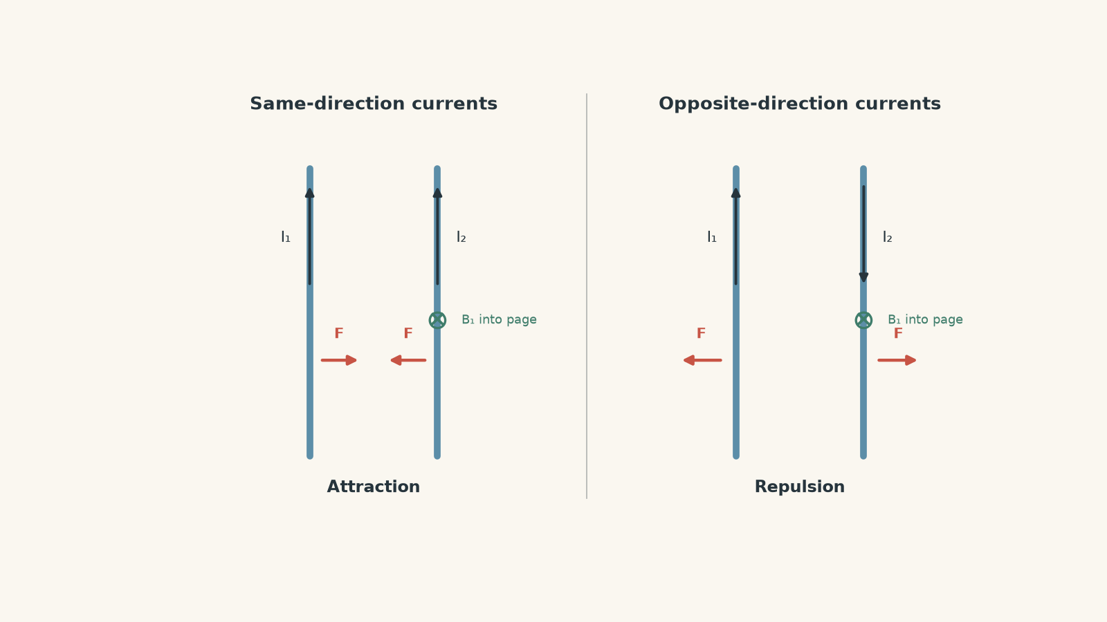
Reverse one current and the motor-effect force reverses. Each wire is pushed away from the other, so opposite-direction currents repel.
The compact rule is:
| Relative current directions | Force |
|---|---|
| Same direction | Attraction |
| Opposite directions | Repulsion |
If you forget that rule, do not guess. Rebuild the answer using the magnetic field from one wire and the force on the other. The direction method is developed more fully in Motor-Effect Direction Rules for HSC Physics Explained.
Worked example: Find the force between two parallel wires
Two long parallel wires are \(4.0\ \text{cm}\) apart. They carry currents of \(3.0\ \text{A}\) and \(5.0\ \text{A}\) in the same direction. Find the force per unit length, and the force acting on a \(0.80\ \text{m}\) section of each wire.
Step 1
\[ d=4.0\ \text{cm}=0.040\ \text{m} \]
Step 2
\[ \begin{aligned} \frac{F}{L} &=\frac{\mu_0I_1I_2}{2\pi d}\\ &=(2.0\times10^{-7}) \frac{(3.0)(5.0)}{0.040}\\ &=7.5\times10^{-5}\ \text{N m}^{-1} \end{aligned} \]
Step 3
\[ \begin{aligned} F &=\left(\frac{F}{L}\right)L\\ &=(7.5\times10^{-5})(0.80)\\ &=6.0\times10^{-5}\ \text{N} \end{aligned} \]
Step 4
The currents are in the same direction, so the wires attract.
The result means each \(0.80\ \text{m}\) section experiences a force of \(6.0\times10^{-5}\ \text{N}\) towards the other wire.
Notice that the equation gave only the magnitude. The current directions had to be considered separately.
04Force per length is often more useful than total force
Why does the equation naturally give \(F/L\)?
Imagine comparing a \(10\ \text{cm}\) section of wire with a \(1.0\ \text{m}\) section. If the field is approximately constant along both, the metre-long section contains ten times as much current-carrying conductor in the field, so it experiences ten times the total force.
The force per metre stays the same.
This makes \(F/L\) especially useful when another quantity is also given “per metre”, such as mass per unit length.
Worked example: Magnetic repulsion supports a wire
A long horizontal wire is fixed below a second parallel wire. The lower wire carries \(30\ \text{A}\). The upper wire has a mass per unit length of \(1.5\ \text{g m}^{-1}\) and is \(8.0\ \text{mm}\) above the lower wire.
Ignoring other supports, what current must flow through the upper wire for magnetic force to balance its weight? State the required current direction relative to the lower wire. Use \(g=9.8\ \text{m s}^{-2}\).
Step 1
The upper wire’s weight acts downwards. The magnetic force must therefore act upwards.
Because the upper wire is above the lower wire, the wires need to repel.
Their currents must flow in opposite directions.
Step 2
\[ 1.5\ \text{g m}^{-1} = 1.5\times10^{-3}\ \text{kg m}^{-1} \]
Let the mass per unit length be \(\lambda\).
The weight per unit length is
\[ \begin{aligned} \frac{W}{L} &=\lambda g\\ &=(1.5\times10^{-3})(9.8)\\ &=1.47\times10^{-2}\ \text{N m}^{-1} \end{aligned} \]
Step 3
The separation is
\[ d=8.0\times10^{-3}\ \text{m} \]
For equilibrium,
\[ \frac{\mu_0I_1I_2}{2\pi d}=\lambda g \]
Using \(\mu_0/(2\pi)=2.0\times10^{-7}\),
\[ (2.0\times10^{-7}) \frac{(30)I_2}{8.0\times10^{-3}} = 1.47\times10^{-2} \]
Step 4
\[ \begin{aligned} I_2 &= \frac{(1.47\times10^{-2})(8.0\times10^{-3})} {(2.0\times10^{-7})(30)}\\ &=19.6\ \text{A} \end{aligned} \]
So the upper wire requires a current of approximately
\[ \boxed{20\ \text{A}} \]
flowing in the opposite direction to the lower wire.
This example is useful because no particular wire length was needed. Weight and magnetic force were both compared per unit length.
05The most tempting misconception: “parallel means zero force”
Students often remember
\[ F=BIL\sin\theta \]
and think, “The wires are parallel, so \(\theta=0^\circ\), which means zero force.”
The problem is that \(\theta\) is not the angle between the two wires.
It is the angle between the current in the wire experiencing the force and the magnetic field at that wire.
For parallel straight wires, the magnetic field from one wire circles around it. At the neighbouring wire, this field is perpendicular to the current.
Therefore,
\[ \theta=90^\circ \]
and the motor-effect force is actually at its maximum for that field strength.
Another tempting mistake is to use the magnetic field from both wires in \(F=BIL\). To find the force on wire 2 due to wire 1, use the field produced by wire 1 at wire 2. A wire’s own magnetic field is not inserted into this simple motor-effect calculation to make it push itself sideways.
06Questions and solutions
Question 1
Two long parallel wires are separated by \(6.0\ \text{cm}\). They carry currents of \(4.0\ \text{A}\) and \(7.5\ \text{A}\) in the same direction.
a. Calculate the force per unit length between the wires.
b. Find the force on a \(1.20\ \text{m}\) section.
c. State whether the force is attractive or repulsive.
Solution 1
The force per unit length is \(1.0\times10^{-4}\ \text{N m}^{-1}\), giving \(1.2\times10^{-4}\ \text{N}\) on a \(1.20\ \text{m}\) section, and the wires attract.
Convert the separation first:
\[ d=6.0\ \text{cm}=0.060\ \text{m} \]
Then
\[ \begin{aligned} \frac{F}{L} &=(2.0\times10^{-7}) \frac{I_1I_2}{d}\\ &=(2.0\times10^{-7}) \frac{(4.0)(7.5)}{0.060}\\ &=1.0\times10^{-4}\ \text{N m}^{-1} \end{aligned} \]
For \(L=1.20\ \text{m}\),
\[ \begin{aligned} F &=\left(\frac{F}{L}\right)L\\ &=(1.0\times10^{-4})(1.20)\\ &=1.2\times10^{-4}\ \text{N} \end{aligned} \]
Because the currents flow in the same direction, the force is attractive.
A common error is to leave \(6.0\ \text{cm}\) in centimetres. The force equation requires metres.
Question 2
Two long parallel wires A and B are \(3.0\ \text{cm}\) apart. A is to the left of B.
Wire A carries \(12\ \text{A}\), and wire B carries \(4.0\ \text{A}\) in the opposite direction. Their mass per unit lengths are \(0.020\ \text{kg m}^{-1}\) for A and \(0.010\ \text{kg m}^{-1}\) for B.
a. Calculate the magnetic force per unit length on each wire.
b. State the force direction on each wire.
c. If both wires are released from rest and can move sideways, calculate their initial transverse accelerations.
Solution 2
Each wire experiences a magnetic force of \(3.2\times10^{-4}\ \text{N m}^{-1}\), but wire B initially accelerates twice as rapidly because its mass per unit length is half as large.
The magnetic force per unit length is
\[ \begin{aligned} \frac{F}{L} &=(2.0\times10^{-7}) \frac{(12)(4.0)}{0.030}\\ &=3.2\times10^{-4}\ \text{N m}^{-1} \end{aligned} \]
The currents are opposite, so the wires repel. Since A is on the left, A is pushed left and B is pushed right.
For a one-metre section of A,
\[ F=3.2\times10^{-4}\ \text{N} \]
and its mass is \(0.020\ \text{kg}\). Therefore,
\[ \begin{aligned} a_A &=\frac{F}{m}\\ &=\frac{3.2\times10^{-4}}{0.020}\\ &=1.6\times10^{-2}\ \text{m s}^{-2} \end{aligned} \]
For a one-metre section of B,
\[ \begin{aligned} a_B &=\frac{3.2\times10^{-4}}{0.010}\\ &=3.2\times10^{-2}\ \text{m s}^{-2} \end{aligned} \]
So A initially accelerates left at
\[ \boxed{1.6\times10^{-2}\ \text{m s}^{-2}} \]
and B accelerates right at
\[ \boxed{3.2\times10^{-2}\ \text{m s}^{-2}} \]
The tempting mistake is to argue that the \(12\ \text{A}\) wire must experience a larger force than the \(4.0\ \text{A}\) wire. It does not. The mutual-force equation contains the product \(I_1I_2\), so the force magnitudes are equal. Different accelerations arise from different masses, not different magnetic-force magnitudes.
Question 3
Three long parallel wires A, B, and C lie in the same plane.
A is \(3.0\ \text{cm}\) to the left of B. C is \(5.0\ \text{cm}\) to the right of B.
A carries \(8.0\ \text{A}\) upwards, while B carries \(6.0\ \text{A}\) downwards.
Determine the magnitude and direction of the current in C so that the net magnetic force on B is zero.
Solution 3
Wire C must carry approximately \(13\ \text{A}\) upwards.
First determine the direction needed.
A and B carry opposite currents, so they repel. Because A is left of B, A pushes B to the right.
For the net force on B to be zero, C must push B to the left.
C lies to the right of B. To push B away from C, B and C must repel, so their currents must be opposite.
B’s current is downwards, so C’s current must be upwards.
Now match the force magnitudes.
The force per unit length on B due to A is
\[ \left(\frac{F}{L}\right)_{AB} = \frac{\mu_0I_AI_B}{2\pi d_{AB}} \]
The force per unit length on B due to C is
\[ \left(\frac{F}{L}\right)_{CB} = \frac{\mu_0I_CI_B}{2\pi d_{CB}} \]
For zero net force,
\[ \frac{\mu_0I_AI_B}{2\pi d_{AB}} = \frac{\mu_0I_CI_B}{2\pi d_{CB}} \]
The common factors cancel:
\[ \frac{I_A}{d_{AB}} = \frac{I_C}{d_{CB}} \]
Therefore,
\[ \begin{aligned} I_C &=I_A\frac{d_{CB}}{d_{AB}}\\ &=(8.0)\frac{0.050}{0.030}\\ &=13.3\ \text{A} \end{aligned} \]
So
\[ \boxed{I_C\approx13\ \text{A upwards}} \]
A tempting approach is to decide that C should carry current downwards because that matches B. But matching currents would make B and C attract, pulling B towards the right, in the same direction as the force from A. Direction must be settled before the magnitudes are equated.
Question 4
Two identical horizontal wires are parallel and have equal currents. Each wire is \(1.20\ \text{m}\) long and has a mass of \(1.8\ \text{g}\).
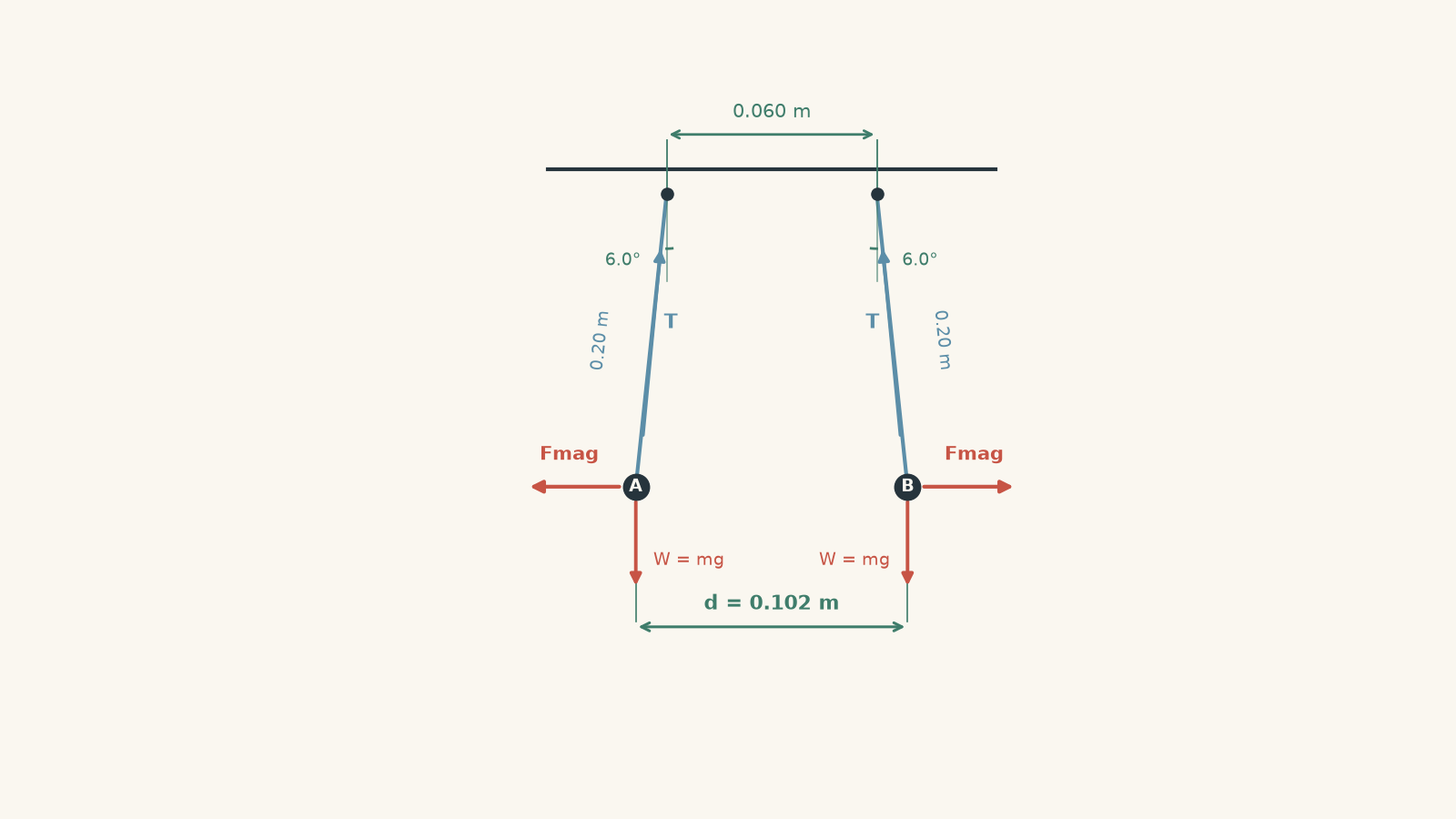
Each end of each wire is suspended from a light insulating string of length \(0.20\ \text{m}\). With no current, the corresponding suspension points above the two wires are \(0.060\ \text{m}\) apart.
When currents are switched on in opposite directions, the wires repel symmetrically. Each suspension string settles at \(6.0^\circ\) from the vertical.
Assume the wires remain horizontal and parallel.
Calculate the current in each wire. Use \(g=9.8\ \text{m s}^{-2}\).
Solution 4
The current in each wire is approximately \(28\ \text{A}\).
The crucial point is that the magnetic force must be calculated using the new separation after the wires move, not the original \(0.060\ \text{m}\) spacing of the support points.
Each wire moves horizontally outwards by
\[ x=(0.20)\sin6.0^\circ \]
so the final wire separation is
\[ \begin{aligned} d &=0.060+2(0.20)\sin6.0^\circ\\ &=0.1018\ \text{m} \end{aligned} \]
Now consider the force equilibrium of one complete wire.
The total upward component of the string tensions balances its weight, while the total horizontal component balances the magnetic force. Therefore,
\[ \tan\theta=\frac{F_{\text{mag}}}{mg} \]
so
\[ F_{\text{mag}}=mg\tan\theta \]
Using
\[ m=1.8\times10^{-3}\ \text{kg} \]
gives
\[ \begin{aligned} F_{\text{mag}} &=(1.8\times10^{-3})(9.8)\tan6.0^\circ\\ &=1.85\times10^{-3}\ \text{N} \end{aligned} \]
The force per unit length is therefore
\[ \begin{aligned} \frac{F}{L} &=\frac{1.85\times10^{-3}}{1.20}\\ &=1.54\times10^{-3}\ \text{N m}^{-1} \end{aligned} \]
Both wires carry the same current magnitude \(I\), so
\[ \frac{F}{L} = \frac{\mu_0I^2}{2\pi d} = (2.0\times10^{-7})\frac{I^2}{d} \]
Substituting,
\[ 1.54\times10^{-3} = (2.0\times10^{-7}) \frac{I^2}{0.1018} \]
Hence,
\[ \begin{aligned} I^2 &= \frac{(1.54\times10^{-3})(0.1018)} {2.0\times10^{-7}}\\ &\approx7.84\times10^2 \end{aligned} \]
and
\[ I\approx28.0\ \text{A} \]
Thus,
\[ \boxed{I\approx28\ \text{A}} \]
The currents must be opposite because the observed motion is repulsion.
There are two tempting shortcuts here. The first is using \(0.060\ \text{m}\) as the wire separation even after the wires move. That overestimates the magnetic field. The second is comparing \(F/L\) directly with the whole wire’s weight \(mg\). One is a force per metre and the other is a total force, so they cannot be equated without accounting for the wire length.
Question 5
Two fixed, long parallel wires A and C are \(0.50\ \text{m}\) apart. They both carry current upwards.
Wire A carries \(3.0\ \text{A}\), and wire C carries \(12\ \text{A}\).
A third long parallel wire B is placed somewhere between them and carries \(5.0\ \text{A}\).
a. Find the position between A and C where the net magnetic force on B is zero when B’s current is upwards.
b. Is this zero-force position stable or unstable against a small sideways displacement? Explain.
c. B’s current is now reversed while A and C remain unchanged. Does the zero-force position move?
d. With B’s current reversed, is the equilibrium stable or unstable?
e. If the magnitude of B’s current is doubled, does the zero-force position change?
Solution 5
Wire B has zero net force \(0.10\ \text{m}\) from A. With B’s current upwards the equilibrium is unstable; reversing B’s current leaves the equilibrium at the same position but makes it stable. Doubling \(I_B\) does not shift the equilibrium position.
Let the distance from A to B be \(x\). The distance from B to C is then
\[ 0.50-x \]
When B’s current is upwards, it is parallel to both outer currents. A attracts B to the left, while C attracts B to the right.
For zero net force, the two magnitudes must be equal:
\[ \frac{\mu_0I_AI_B}{2\pi x} = \frac{\mu_0I_CI_B}{2\pi(0.50-x)} \]
Cancel the common factors, including \(I_B\):
\[ \frac{I_A}{x} = \frac{I_C}{0.50-x} \]
Substitute the currents:
\[ \frac{3.0}{x} = \frac{12}{0.50-x} \]
Cross-multiplying,
\[ \begin{aligned} 3.0(0.50-x)&=12x\\ 1.50-3.0x&=12x\\ 1.50&=15x\\ x&=0.10\ \text{m} \end{aligned} \]
So B must sit
\[ \boxed{0.10\ \text{m from A}} \]
and therefore \(0.40\ \text{m}\) from C.
It may initially look strange that B sits much closer to the weaker \(3.0\ \text{A}\) wire. That is exactly what must happen. A weaker current needs a smaller separation to produce a magnetic force equal to the force from the stronger \(12\ \text{A}\) wire.
Now test stability rather than merely noticing that the net force is zero.
Suppose B moves slightly to the right. Its distance from C decreases, so C’s attraction becomes stronger. At the same time, its distance from A increases, so A’s attraction becomes weaker.
The resulting net force is therefore to the right – in the same direction as the displacement.
So the original equilibrium is
\[ \boxed{\text{unstable}} \]
The wire is like a ball balanced exactly on top of a hill: zero force at one precise location does not mean disturbances are corrected.
Now reverse B’s current.
B is antiparallel to both A and C, so both interactions become repulsive. The force magnitudes still contain
\[ I_AI_B \quad\text{and}\quad I_CI_B \]
and reversing the current changes both force directions together. The equality condition is unchanged.
Therefore the zero-force position remains
\[ \boxed{0.10\ \text{m from A}} \]
But its stability changes.
Move B slightly right, towards C. The repulsion from nearby C becomes stronger and pushes B left. The repulsion from A becomes weaker because A is now farther away.
The net force is therefore leftwards, back towards the equilibrium position.
So with B reversed, the equilibrium is
\[ \boxed{\text{stable}} \]
Finally, doubling \(I_B\) multiplies both opposing magnetic forces by the same factor. In
\[ \frac{\mu_0I_AI_B}{2\pi x} = \frac{\mu_0I_CI_B}{2\pi(0.50-x)} \]
\(I_B\) cancels completely.
Therefore doubling \(I_B\) does not change the equilibrium position.
The trap in this problem is treating “zero net force” as automatically meaning “stable”. Stability requires a second question: after a small displacement, does the new net force push the object back towards equilibrium or farther away?
That distinction becomes useful whenever several magnetic forces act at once. Once you can calculate each \(F/L\), assign its direction, and add the forces as vectors, parallel-wire questions become part of a much broader idea: magnetic fields do not merely produce forces; the way those forces change with position can determine whether an arrangement holds itself together or falls away from equilibrium.