
Force on a Current-Carrying Conductor: HSC Physics Guide
Learn how to use F = BIl sin θ correctly, identify the active conductor length, and avoid common motor-effect mistakes in HSC Physics.
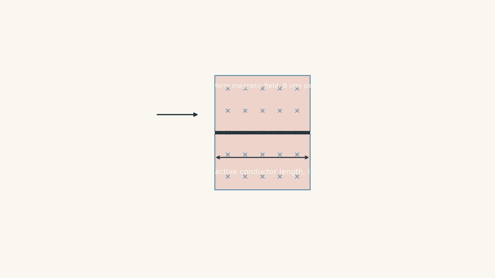
A 50 cm wire carries current, but only an 8 cm section sits inside a magnetic field. Which length belongs in \(F = BIl\sin\theta\): 50 cm or 8 cm?
The answer is 8 cm. The rest of the wire may move because it is connected to that section, but the magnetic force is generated only where the current-carrying conductor overlaps the magnetic field. Getting that active conductor length right is one of the most important parts of motor-effect calculations.
01Where does the force actually come from?
Picture a straight wire carrying a steady current through a magnetic field. Inside the metal, charged particles are moving. A moving charge in a magnetic field experiences a magnetic force.
That sideways force is transferred to the metal lattice, so the conductor itself experiences a force. This is the motor effect.
Now imagine that only part of the wire is inside the field. Charges outside the field do not experience that magnetic force. So only the section inside the field contributes directly to the force on the conductor.
A slightly silly model is a long pool noodle passing through a narrow car-wash brush. The whole noodle might move when the brushes shove it, but only the bit actually inside the brushes is being directly pushed.
The analogy breaks because a magnetic field is not physically rubbing against the wire. More importantly, magnetic force also depends on the angle between the current and the magnetic field.
02The force equation
For a straight conductor carrying current through a uniform magnetic field,
\[ F = BIl\sin\theta \]
where:
| Symbol | Meaning | Unit |
|---|---|---|
| \(F\) | magnitude of the magnetic force on the conductor | newton, N |
| \(B\) | magnetic flux density | tesla, T |
| \(I\) | conventional current | ampere, A |
| \(l\) | active conductor length inside the magnetic field | metre, m |
| \(\theta\) | angle between the conventional current direction and the magnetic field | degrees |
Two details deserve attention.
First, \(l\) is not automatically the total length of the wire. It is the length of the relevant conductor section within the magnetic field.
Second, \(\theta\) is the angle between the current and the magnetic field. It is not automatically the angle between the wire and a boundary, the table, the page, or anything else drawn in the question.
The equation gives the magnitude of the force. Its direction is perpendicular to both the current and magnetic field. If you need to revise that separately, see Motor-Effect Direction Rules for HSC Physics Explained.
03Why is there a \(\sin\theta\)?
Suppose the conductor points in exactly the same direction as the magnetic field.
What force should you expect?
The magnetic force is zero. A moving charge does not experience magnetic force from the component of the field parallel to its motion.
At the other extreme, put the conductor perpendicular to the field. Now the force is as large as possible for that \(B\), \(I\), and \(l\).
The sine factor captures those two limits:
| Angle between current and field | \(\sin\theta\) | Force |
|---|---|---|
| \(0^\circ\) | 0 | zero |
| \(30^\circ\) | 0.5 | \(0.5BIl\) |
| \(90^\circ\) | 1 | maximum, \(BIl\) |
| \(180^\circ\) | 0 | zero |
You can think of \(l\sin\theta\) as the component of the active conductor length perpendicular to the magnetic field.
That does not mean you should replace the active length with some random perpendicular distance from the diagram. First find the actual conductor length inside the field. Then account for its angle to the field using \(\sin\theta\).
For a closer look at the limiting cases, see Maximum and Zero Motor-Effect Force in HSC Physics.
04How to identify the active conductor length
A reliable approach is:
- Locate the region where the magnetic field exists.
- Trace the conductor through that region.
- Find the actual length of conductor inside it.
- Ignore conductor outside the field when calculating that field’s force.
- If \(B\), the current direction, or the angle changes along the conductor, split the conductor into suitable sections and consider their forces separately.
The third point causes the most trouble.
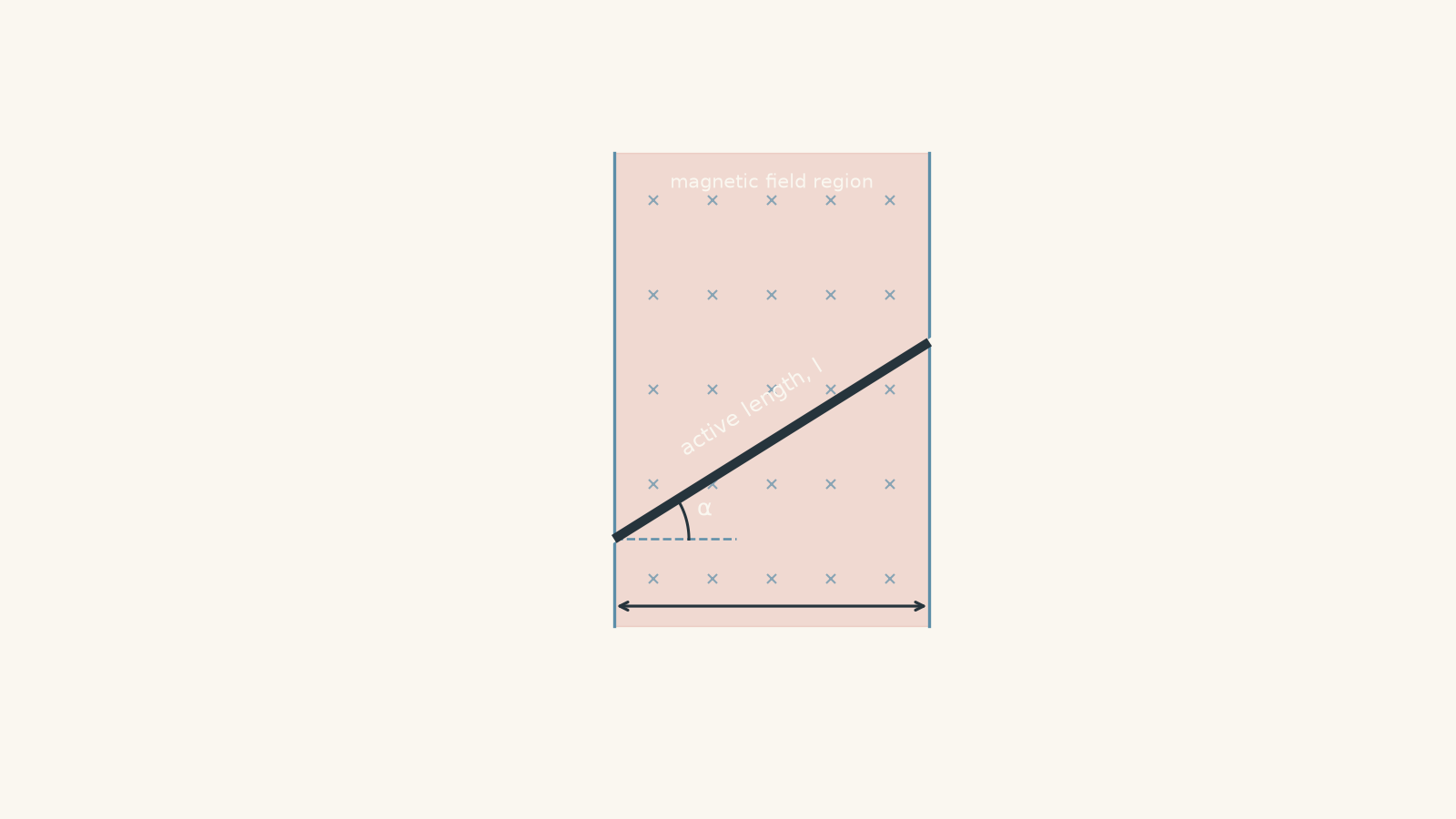
Suppose a magnetic-field region is 10 cm wide from left to right. A wire cuts diagonally across it. Is the active conductor length 10 cm?
Not necessarily.
The 10 cm is only the horizontal width of the field region. The piece of wire inside the field is longer because it runs diagonally.
For example, if the wire makes an angle \(\alpha\) to the horizontal and crosses two vertical boundaries separated by a distance \(w\),
\[ \cos\alpha = \frac{w}{l} \]
so
\[ l = \frac{w}{\cos\alpha}. \]
That \(l\) is the actual active conductor length.
Worked example: Force on a perpendicular conductor
A wire carries a current of \(3.2\text{ A}\). A \(0.18\text{ m}\) section of the wire lies in a uniform magnetic field of \(0.40\text{ T}\). The wire is perpendicular to the magnetic field. Calculate the magnitude of the force on the wire.
Step 1
Only \(0.18\text{ m}\) of conductor is in the field, so
\[ l = 0.18\text{ m}. \]
Step 2
The current and field are perpendicular:
\[ \theta = 90^\circ, \qquad \sin90^\circ = 1. \]
Step 3
\[ \begin{aligned} F &= BIl\sin\theta\\ &=(0.40)(3.2)(0.18)\sin90^\circ\\ &=0.2304\text{ N}. \end{aligned} \]
Step 4
\[ F \approx 0.23\text{ N}. \]
The field exerts a magnetic force of about \(0.23\text{ N}\) on the active \(0.18\text{ m}\) section. Because the current is perpendicular to the field, the force has its maximum possible magnitude for these values of \(B\), \(I\), and \(l\).
Worked example: Finding the active length first
A \(0.60\text{ m}\) straight wire passes diagonally through a uniform magnetic-field region. The region has vertical boundaries separated by \(0.12\text{ m}\) horizontally. The wire makes an angle of \(40^\circ\) above the horizontal.
The wire carries \(4.5\text{ A}\). The magnetic field has magnitude \(0.75\text{ T}\) and points \(10^\circ\) above the horizontal. Calculate the magnitude of the magnetic force on the wire inside the field.
Step 1
The wire is \(0.60\text{ m}\) long, but most of it is outside the magnetic field. We need the diagonal section between the two field boundaries.
If that active length is \(l\),
\[ \cos40^\circ = \frac{0.12}{l}. \]
Therefore,
\[ \begin{aligned} l &= \frac{0.12}{\cos40^\circ}\\ &=0.1566\text{ m}\\ &\approx 0.157\text{ m}. \end{aligned} \]
Step 2
The current points \(40^\circ\) above horizontal, while the magnetic field points \(10^\circ\) above horizontal.
Therefore,
\[ \theta = 40^\circ-10^\circ=30^\circ. \]
Notice that \(40^\circ\) is not the angle for the force equation. It describes the wire relative to the horizontal. We need the angle between the current and the magnetic field.
Step 3
\[ \begin{aligned} F &=(0.75)(4.5)(0.1566)\sin30^\circ\\ &=(0.75)(4.5)(0.1566)(0.5)\\ &=0.264\text{ N}. \end{aligned} \]
Step 4
The magnetic force has magnitude
\[ F \approx 0.26\text{ N}. \]
Two separate geometric decisions were needed: the diagram determined the active conductor length, and the relative directions of current and field determined \(\theta\).
05The most tempting mistakes
| Tempting approach | Why it fails | Better decision |
|---|---|---|
| Use the total wire length | Parts outside the magnetic field do not contribute to that field’s force | Use only the conductor inside the field |
| Use the width of the field region as \(l\) | A diagonal conductor may travel farther than the region’s horizontal or vertical width | Find the actual length along the wire |
| Use the angle shown next to the wire | That angle may be relative to a boundary or horizontal line | Find the angle between current and \(B\) |
| Assume a larger angle always means a larger force | \(\sin\theta\) rises to \(90^\circ\), then falls again | Use \(\sin\theta\), not the numerical size of \(\theta\) |
| Add forces from several sections as ordinary numbers | Magnetic force has direction | Combine the forces as vectors |
There is one more subtle point. If a conductor bends inside a field, the different sections may experience forces in different directions. You cannot generally add all their lengths and put the total into one \(BIl\sin\theta\) calculation.
For each straight section, the more precise vector relationship is
\[ \vec F = I\vec l\times\vec B, \]
where \(\vec l\) points along the conventional current and has magnitude equal to the active length of that straight section.
You do not need to turn every HSC question into a vector-product exercise. The useful idea is simpler: if the conductor changes direction, check whether the force direction changes too.
06Questions and solutions
Question 1
A straight conductor carries a current of \(4.0\text{ A}\). A \(0.20\text{ m}\) section is perpendicular to a uniform magnetic field of \(0.35\text{ T}\).
Calculate the magnitude of the magnetic force on the conductor.
Solution 1
The magnetic force is \(0.28\text{ N}\).
The active conductor length is \(0.20\text{ m}\), and the current is perpendicular to the field, so \(\theta=90^\circ\).
\[ \begin{aligned} F&=BIl\sin\theta\\ &=(0.35)(4.0)(0.20)\sin90^\circ\\ &=0.28\text{ N}. \end{aligned} \]
A common unnecessary step is to search for some other angle in the diagram. When the question tells you the conductor is perpendicular to the magnetic field, the relevant angle is already \(90^\circ\).
Question 2
A straight wire crosses a uniform magnetic-field region bounded by two vertical lines \(0.14\text{ m}\) apart. The wire makes an angle of \(30^\circ\) above the horizontal and carries a current of \(6.0\text{ A}\) from left to right.
The magnetic field has magnitude \(0.55\text{ T}\) and points \(75^\circ\) above the horizontal.
Calculate:
(a) the active conductor length,
(b) the angle \(\theta\) required in \(F=BIl\sin\theta\), and
(c) the magnitude of the magnetic force.
Solution 2
The active length is \(0.162\text{ m}\), the required angle is \(45^\circ\), and the magnetic force is approximately \(0.38\text{ N}\).
For part (a), the \(0.14\text{ m}\) separation is horizontal. It is not the length along the diagonal wire.
\[ \cos30^\circ=\frac{0.14}{l} \]
so
\[ \begin{aligned} l&=\frac{0.14}{\cos30^\circ}\\ &=0.1617\text{ m}\\ &\approx0.162\text{ m}. \end{aligned} \]
For part (b), the current points \(30^\circ\) above horizontal and the field points \(75^\circ\) above horizontal. Therefore,
\[ \theta=75^\circ-30^\circ=45^\circ. \]
For part (c),
\[ \begin{aligned} F &=BIl\sin\theta\\ &=(0.55)(6.0)(0.1617)\sin45^\circ\\ &=0.377\text{ N}\\ &\approx0.38\text{ N}. \end{aligned} \]
The tempting route is to substitute \(l=0.14\text{ m}\) and \(\theta=30^\circ\). Both quantities would be wrong. The \(0.14\text{ m}\) value is a horizontal displacement, while \(30^\circ\) is measured from the horizontal rather than from the magnetic field.
Question 3
A horizontal wire carries \(5.0\text{ A}\) to the right through two adjacent magnetic-field regions.
In region A, \(0.12\text{ m}\) of wire lies in a \(0.80\text{ T}\) field directed into the page.
In region B, \(0.20\text{ m}\) of wire lies in a \(0.48\text{ T}\) field directed out of the page.
The current is perpendicular to both magnetic fields.
Determine the net magnetic force on the wire and explain why simply using the total active length of \(0.32\text{ m}\) in one force calculation is invalid.
Solution 3
The net magnetic force is \(0\text{ N}\) because the two regions produce equal forces in opposite directions.
For region A,
\[ \begin{aligned} F_A &=B_AI l_A\sin90^\circ\\ &=(0.80)(5.0)(0.12)\\ &=0.48\text{ N}. \end{aligned} \]
With current to the right and magnetic field into the page, the force is upward.
For region B,
\[ \begin{aligned} F_B &=B_BI l_B\sin90^\circ\\ &=(0.48)(5.0)(0.20)\\ &=0.48\text{ N}. \end{aligned} \]
The field has reversed direction, so this force is downward.
Therefore,
\[ F_{\text{net}}=0.48-0.48=0\text{ N}. \]
A student might add the lengths to get \(0.32\text{ m}\), then try to perform one \(BIl\) calculation. That does not work because there is no single magnetic field applying to the whole \(0.32\text{ m}\): its magnitude and direction differ between the two regions.
The zero net force also does not mean that no magnetic forces act. Two non-zero forces act, but their vector sum is zero.
Question 4
A bent wire lies entirely within a uniform \(0.40\text{ T}\) magnetic field directed into the page. It carries a current of \(3.0\text{ A}\).
The current first travels \(0.20\text{ m}\) horizontally to the right along segment AB, then turns through \(90^\circ\) and travels \(0.15\text{ m}\) vertically upward along segment BC.
Determine the magnitude and direction of the net magnetic force on the bent section.
A student argues that the total active length is \(0.35\text{ m}\), so the force must be
\[ F=(0.40)(3.0)(0.35)=0.42\text{ N}. \]
Explain the error.
Solution 4
The net force is \(0.30\text{ N}\), directed \(36.9^\circ\) west of north.
Both wire sections are perpendicular to the magnetic field, but their current directions differ. Their force directions therefore differ as well.
For AB,
\[ \begin{aligned} F_{AB} &=BIl_{AB}\\ &=(0.40)(3.0)(0.20)\\ &=0.24\text{ N}. \end{aligned} \]
Current is to the right and \(B\) is into the page, so the force on AB is upward.
For BC,
\[ \begin{aligned} F_{BC} &=BIl_{BC}\\ &=(0.40)(3.0)(0.15)\\ &=0.18\text{ N}. \end{aligned} \]
Current is upward and \(B\) is into the page, so the force on BC is to the left.
The two forces are perpendicular, so the net magnitude is
\[ \begin{aligned} F_{\text{net}} &=\sqrt{(0.24)^2+(0.18)^2}\\ &=\sqrt{0.0900}\\ &=0.30\text{ N}. \end{aligned} \]
Its direction relative to north is
\[ \begin{aligned} \tan\phi&=\frac{0.18}{0.24}\\ \phi&=36.9^\circ. \end{aligned} \]
So the net force is \(36.9^\circ\) west of north.
The tempting \(0.42\text{ N}\) calculation treats the bent wire as though every part of its \(0.35\text{ m}\) active length experiences force in the same direction. It does not. Segment AB is pushed north, while BC is pushed west.
Adding active lengths before using \(F=BIl\) is only safe when the relevant segments have the same current direction, magnetic field, and therefore force direction.
Question 5
A uniform magnetic field of \(0.60\text{ T}\) points vertically upward in the plane of the page. The field occupies a tall strip bounded by two vertical lines separated horizontally by \(w=0.10\text{ m}\).
A straight wire carrying \(4.0\text{ A}\) enters through the left boundary and exits through the right boundary. The wire makes an angle \(\alpha\) above the horizontal. Assume \(\alpha\) is restricted to values for which the wire reaches the right boundary before any other boundary.
A student predicts that increasing \(\alpha\) must increase the magnetic force because a longer section of wire lies inside the field.
Another student predicts that increasing \(\alpha\) must decrease the force because the wire becomes more nearly parallel to the field.
Determine which prediction is correct by:
(a) finding the active length in terms of \(w\) and \(\alpha\),
(b) finding \(\theta\) in terms of \(\alpha\),
(c) deriving the force in terms of \(B\), \(I\), and \(w\),
(d) calculating the force for \(\alpha=0^\circ\) and \(\alpha=45^\circ\), and
(e) explaining why your result must not be applied blindly at exactly \(\alpha=90^\circ\).
Solution 5
Neither student’s prediction is correct: for every allowed value of \(\alpha\), the magnetic force has the same magnitude, \(0.24\text{ N}\). The increase in active conductor length exactly cancels the decrease in the sine factor.
For part (a), the horizontal separation of the boundaries is \(w\). The active wire forms the hypotenuse of a right triangle:
\[ \cos\alpha=\frac{w}{l}. \]
Therefore,
\[ l=\frac{w}{\cos\alpha}. \]
So the first student has noticed something real: increasing \(\alpha\) increases the active length.
For part (b), the magnetic field points vertically, which is \(90^\circ\) above horizontal. The current points at \(\alpha\) above horizontal.
Therefore,
\[ \theta=90^\circ-\alpha. \]
As \(\alpha\) increases, \(\theta\) decreases. So the second student has also noticed something real.
For part (c),
\[ F=BIl\sin\theta. \]
Substitute the expressions for \(l\) and \(\theta\):
\[ \begin{aligned} F &=BI\left(\frac{w}{\cos\alpha}\right) \sin(90^\circ-\alpha). \end{aligned} \]
Using
\[ \sin(90^\circ-\alpha)=\cos\alpha, \]
we get
\[ \begin{aligned} F &=BI\left(\frac{w}{\cos\alpha}\right)\cos\alpha\\ &=BIw. \end{aligned} \]
The angle has disappeared.
For part (d),
\[ \begin{aligned} F &=BIw\\ &=(0.60)(4.0)(0.10)\\ &=0.24\text{ N}. \end{aligned} \]
So at \(\alpha=0^\circ\),
\[ F=0.24\text{ N}, \]
and at \(\alpha=45^\circ\),
\[ F=0.24\text{ N}. \]
The result initially feels strange because each student’s argument sounds reasonable in isolation. A steeper wire really does put more conductor in the field, but it also makes the current more nearly parallel to the field. In this particular geometry, those effects cancel exactly.
For part (e), exactly \(\alpha=90^\circ\) is not part of the situation we derived.
The expression
\[ l=\frac{w}{\cos\alpha} \]
assumes the wire enters one vertical boundary and exits the other. At \(90^\circ\), the wire is vertical, so it never crosses from the left boundary to the right boundary at all. Since \(\cos90^\circ=0\), the expression for \(l\) also becomes undefined.
If you instead placed a finite vertical wire inside the field, its current would be parallel to \(B\), giving
\[ F=BIl\sin0^\circ=0. \]
The apparent contradiction comes from changing the geometry while pretending the original assumptions still apply. Checking whether an equation’s assumptions survive a limiting case is often more important than performing another calculation.
07What this idea lets you do next
Once you can identify the active conductor length and the correct angle, the motor effect becomes much easier to extend.
In a current-carrying coil, different sides of the coil experience magnetic forces in different directions. Those forces can form a turning effect, which is the basis of electric motors. The same force law also helps explain why two parallel current-carrying wires exert forces on one another: each wire produces a magnetic field that acts on the current in the other wire.
That connection is developed in Force Between Parallel Current-Carrying Wires: HSC Physics.