
Series Circuits: Current, Voltage, Resistance and Power
Learn how to analyse current, voltage, resistance, and power in series circuits using clear reasoning, worked examples, and HSC-style practice.
Connect two resistors in series to a battery. One resistor has three times the resistance of the other. Before doing any maths, predict two things: does less current come out of the first resistor than went into it, and does each resistor get half the battery’s voltage?
Both predictions are tempting. Both are wrong.
In a series circuit, the same current passes through every component. The voltage is shared, but not usually equally. For ordinary fixed resistors, the larger resistance gets the larger voltage drop. Understanding why gives you nearly everything you need to analyse current, voltage, resistance, and power in a series network.
01What makes a circuit “series”?
A series circuit has a single path for current. There are no junctions where the current can split into different branches.
Imagine people moving in a conga line through several turnstiles. If 20 people pass the first turnstile each minute, then 20 people per minute must also pass the second. People don’t disappear between them.
Current behaves similarly. If charge flows through one component at \(0.50\ \text{A}\), the steady current through every other component in that series loop is also \(0.50\ \text{A}\).
The analogy has a limit. Charges aren’t actually travelling from the battery through an initially empty wire like people entering a queue. Charge carriers are already present throughout a metal conductor, and the electric field established around the circuit causes them to drift. If that part feels unfamiliar, it is worth revisiting how electric current behaves in conductors.
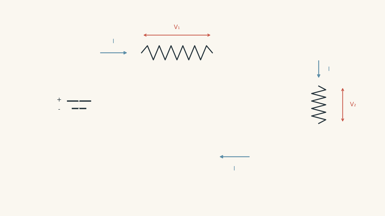
For an ideal series circuit,
\[
I_{\text{source}} = I_1 = I_2 = I_3 = \cdots
\]
where \(I\) is current measured in amperes, \(\text{A}\).
This is a consequence of charge conservation. In steady operation, charge isn’t continuously piling up between components.
02Current is not “used up”
A common mistake is to picture current being consumed by each resistor.
Suppose \(0.40\ \text{A}\) enters the first resistor. A student might predict that only \(0.30\ \text{A}\) leaves because the resistor has “used” some current.
That would mean charge was accumulating inside the resistor. If that kept happening, the amount of stored charge would grow every second. That isn’t what happens in a steady DC circuit.
What a resistor transfers is energy, not charge.
The same rate of charge flow continues around the circuit, but electrical potential energy is transferred into thermal energy and other forms as the charge passes through components.
That distinction is why a circuit can have:
- the same current everywhere in series, but
- different potential differences across different components.
03Voltage tells you about energy transfer
Potential difference measures energy transferred per unit charge.
If a \(12\ \text{V}\) source supplies \(12\ \text{J}\) of energy to each coulomb of charge, the components in the loop must together transfer that \(12\ \text{J}\) per coulomb elsewhere.
For two resistors,
\[
V_s = V_1 + V_2
\]
where:
- \(V_s\) is the supply potential difference in volts,
- \(V_1\) is the potential difference across the first resistor, and
- \(V_2\) is the potential difference across the second resistor.
For more components,
\[
V_s = V_1 + V_2 + V_3 + \cdots
\]
This is an energy conservation statement. Around a complete loop, the energy gained per coulomb from the source matches the energy transferred per coulomb by the components.
For ideal connecting wires, we treat the wire resistance as negligible, so their voltage drop is approximately zero. Real wires do have some resistance, but this approximation is usually appropriate in HSC circuit calculations unless information suggests otherwise.
04Why the voltage does not usually split equally
Now return to the original prediction. Suppose one series resistor has three times the resistance of another.
Which gets the larger voltage drop?
The larger resistor does.
For a fixed resistor that obeys Ohm’s law,
\[
V = IR
\]
where \(V\) is the potential difference across the resistor, \(I\) is its current, and \(R\) is its resistance in ohms, \(\Omega\).
Every resistor in series has the same \(I\). Therefore, if one resistor has three times the resistance, its voltage drop is also three times as large.
For example, if
\[
R_2 = 3R_1,
\]
then
\[
V_2 = IR_2 = I(3R_1) = 3V_1.
\]
The voltage therefore divides in proportion to resistance.
This reasoning assumes that the components can be treated as fixed resistors. A filament lamp, for example, can change resistance as its temperature changes. The current is still the same through series components, and the voltage drops still add to the supply voltage, but you cannot blindly treat the lamp’s resistance as constant.
For a refresher on when \(V=IR\) can be used directly, see Ohm’s Law in HSC Physics.
05Why series resistances add
Suppose two resistors \(R_1\) and \(R_2\) are connected in series.
The supply voltage is
\[
V_s = V_1 + V_2.
\]
Using \(V=IR\),
\[
V_s = IR_1 + IR_2.
\]
The current \(I\) is common to both resistors, so
\[
V_s = I(R_1 + R_2).
\]
If we replace the two resistors with a single equivalent resistance \(R_{\text{eq}}\), it must draw the same current from the same supply:
\[
V_s = IR_{\text{eq}}.
\]
Therefore,
\[
R_{\text{eq}} = R_1 + R_2.
\]
For any number of fixed resistors in series,
\[
R_{\text{eq}} = R_1 + R_2 + R_3 + \cdots
\]
Adding another resistor in series therefore increases the total resistance of the circuit.
If the supply voltage remains fixed, increasing \(R_{\text{eq}}\) means the circuit current decreases:
\[
I = \frac{V_s}{R_{\text{eq}}}.
\]
This system-wide change matters. You cannot add a resistor and assume all the other currents, voltages, and powers stay as they were.
06The four rules worth knowing
| Quantity | Series circuit rule | What it means |
|---|---|---|
| Current | \(I_1=I_2=I_3=\cdots\) | The same current passes through every series component |
| Resistance | \(R_{\text{eq}}=R_1+R_2+\cdots\) | Series resistances add |
| Voltage | \(V_s=V_1+V_2+\cdots\) | The source voltage is shared between the components |
| Power | \(P_{\text{total}}=P_1+P_2+\cdots\) | Total energy transfer rate equals the sum for the components |
The table is useful, but don’t treat it as four unrelated formulas. Current conservation and energy conservation are doing most of the work.
07A useful voltage-divider relationship
For two fixed resistors in series,
\[
I = \frac{V_s}{R_1+R_2}.
\]
The voltage across \(R_1\) is therefore
\[
V_1 = IR_1
= \frac{V_sR_1}{R_1+R_2}.
\]
Similarly,
\[
V_2 = \frac{V_sR_2}{R_1+R_2}.
\]
More generally,
\[
V_i = V_s\frac{R_i}{R_{\text{eq}}},
\]
where \(V_i\) is the voltage across a particular resistor \(R_i\).
You do not need to memorise this as a mysterious new law. It comes directly from two facts:
- the current is the same through each resistor, and
- \(V=IR\).
If a resistor contains one quarter of the total series resistance, it receives one quarter of the supply voltage.
08Power in a series circuit
Electrical power is the rate at which energy is transferred.
For a component,
\[
P=VI,
\]
where \(P\) is power in watts, \(V\) is the potential difference across the component, and \(I\) is the current through it.
For a fixed resistor, combining \(P=VI\) with Ohm’s law gives
\[
P=I^2R
\]
and
\[
P=\frac{V^2}{R}.
\]
These forms are equivalent when applied correctly.
There is an important trap here. In \(P=V^2/R\), \(V\) must be the voltage across that resistor. You cannot automatically substitute the total supply voltage for every resistor in a series circuit.
Within one series circuit, all resistors carry the same current. So
\[
P_i=I^2R_i.
\]
That means a larger resistance dissipates more power than a smaller resistance when they are carrying the same current.
But be careful when comparing two different circuits. Changing a resistance usually changes the current as well. A larger resistance does not automatically mean more power after the whole circuit has been altered.
09Worked example: Two resistors on a 12 V supply
Two fixed resistors of \(4.0\ \Omega\) and \(8.0\ \Omega\) are connected in series across an ideal \(12\ \text{V}\) source. Calculate the total resistance, circuit current, voltage across each resistor, and power dissipated by each resistor.
Step 1
\[
R_{\text{eq}}=4.0+8.0=12\ \Omega
\]
The complete circuit behaves, from the source’s point of view, like a \(12\ \Omega\) resistance.
Step 2
\[
I=\frac{V_s}{R_{\text{eq}}}
=\frac{12}{12}
=1.0\ \text{A}
\]
So \(1.0\ \text{A}\) passes through both resistors.
Step 3
\[
\begin{aligned}
V_1 &= IR_1=(1.0)(4.0)=4.0\ \text{V}\\
V_2 &= IR_2=(1.0)(8.0)=8.0\ \text{V}
\end{aligned}
\]
Check the energy accounting:
\[
V_1+V_2=4.0+8.0=12\ \text{V}.
\]
The \(8.0\ \Omega\) resistor has twice the resistance, so it receives twice the voltage drop.
Step 4
Using \(P=I^2R\),
\[
\begin{aligned}
P_1&=(1.0)^2(4.0)=4.0\ \text{W}\\
P_2&=(1.0)^2(8.0)=8.0\ \text{W}
\end{aligned}
\]
The larger resistor dissipates more power because both resistors carry the same \(1.0\ \text{A}\) current.
The total is
\[
P_{\text{total}}=4.0+8.0=12\ \text{W}.
\]
That agrees with the power supplied:
\[
P_{\text{source}}=V_sI=(12)(1.0)=12\ \text{W}.
\]
The power calculation has therefore passed an independent check.
10Worked example: Working backwards from total power
A \(4.0\ \Omega\) resistor and an unknown resistor \(R\) are connected in series across an ideal \(18\ \text{V}\) source. The source supplies \(27\ \text{W}\) to the circuit. Find \(R\), the voltage across each resistor, and the power dissipated by each resistor.
Here the total resistance is not given directly. Starting with \(R_{\text{eq}}=R_1+R_2\) would leave too many unknowns. The total power gives us a better entry point.
Step 1
For the complete circuit,
\[
P_{\text{total}}=V_sI.
\]
Therefore,
\[
I=\frac{P_{\text{total}}}{V_s}
=\frac{27}{18}
=1.5\ \text{A}.
\]
Because the components are in series, this \(1.5\ \text{A}\) passes through both resistors.
Step 2
\[
R_{\text{eq}}=\frac{V_s}{I}
=\frac{18}{1.5}
=12\ \Omega.
\]
Step 3
\[
R_{\text{eq}}=R_1+R
\]
so
\[
12=4.0+R.
\]
Therefore,
\[
R=8.0\ \Omega.
\]
Step 4
\[
\begin{aligned}
V_1&=(1.5)(4.0)=6.0\ \text{V}\\
V_2&=(1.5)(8.0)=12\ \text{V}.
\end{aligned}
\]
Their sum is \(18\ \text{V}\), as required.
Step 5
\[
\begin{aligned}
P_1&=V_1I=(6.0)(1.5)=9.0\ \text{W}\\
P_2&=V_2I=(12)(1.5)=18\ \text{W}.
\end{aligned}
\]
Again,
\[
P_1+P_2=9.0+18=27\ \text{W}.
\]
The unknown \(8.0\ \Omega\) resistor receives twice the voltage and dissipates twice the power of the \(4.0\ \Omega\) resistor because they carry the same current.
11A reliable way to attack series-circuit questions
When a question contains several electrical quantities, resist the urge to grab whichever formula contains the unknown. Work through the circuit as a system.
A reliable order is:
- Confirm it is actually series. There should be one current path through the components you are analysing.
- Find the equivalent resistance if the individual resistances are known.
- Find the common current using the total supply voltage and equivalent resistance.
- Find individual voltage drops using \(V_i=IR_i\).
- Find individual powers using whichever valid form has the quantities you already know.
- Check the totals. Individual voltage drops should add to the supply voltage, and individual powers should add to the total supplied power.
Sometimes the information suggests a different starting point. In the second worked example, total power gave the current first. The physics rules did not change, only the most efficient route through them did.
12The misconception that causes the most trouble
Suppose a \(6.0\ \Omega\) resistor is connected directly across a \(12\ \text{V}\) supply. You then add another \(6.0\ \Omega\) resistor in series.
A student might say, “The first resistor is still connected to the same 12 V battery, so it should still have 12 V across it.”
That sounds reasonable if you think the battery simply gives every component \(12\ \text{V}\).
But a battery provides \(12\ \text{V}\) across the whole network.
Initially,
\[
I=\frac{12}{6.0}=2.0\ \text{A}.
\]
After the second resistor is added,
\[
R_{\text{eq}}=6.0+6.0=12\ \Omega,
\]
so
\[
I=\frac{12}{12}=1.0\ \text{A}.
\]
The voltage across the original resistor is now
\[
V_1=IR_1=(1.0)(6.0)=6.0\ \text{V}.
\]
Adding the second resistor changed the total resistance, which changed the current, which changed the voltage across the first resistor.
That chain of reasoning is more useful than memorising that “equal resistors split voltage equally”. It still works when the resistors aren’t equal.
13Questions and solutions
Question 1
A \(5.0\ \Omega\) resistor and a \(10\ \Omega\) resistor are connected in series across an ideal \(15\ \text{V}\) supply.
Calculate the circuit current and the potential difference across each resistor.
Solution 1
The circuit current is \(1.0\ \text{A}\), with \(5.0\ \text{V}\) across the \(5.0\ \Omega\) resistor and \(10\ \text{V}\) across the \(10\ \Omega\) resistor.
First find the equivalent resistance:
\[
R_{\text{eq}}=5.0+10=15\ \Omega.
\]
The common series current is
\[
I=\frac{V_s}{R_{\text{eq}}}
=\frac{15}{15}
=1.0\ \text{A}.
\]
Now use \(V=IR\) for each resistor:
\[
\begin{aligned}
V_1&=(1.0)(5.0)=5.0\ \text{V}\\
V_2&=(1.0)(10)=10\ \text{V}.
\end{aligned}
\]
The drops add correctly:
\[
5.0+10=15\ \text{V}.
\]
The \(10\ \Omega\) resistor receives twice the voltage because it has twice the resistance while carrying the same current.
Question 2
Three resistors of \(2.0\ \Omega\), \(3.0\ \Omega\), and \(7.0\ \Omega\) are connected in series across an ideal \(24\ \text{V}\) source.
Calculate the current, the voltage across each resistor, the power dissipated by each resistor, and the total power supplied by the source.
Solution 2
The current is \(2.0\ \text{A}\). The voltage drops are \(4.0\ \text{V}\), \(6.0\ \text{V}\), and \(14\ \text{V}\), and the corresponding powers are \(8.0\ \text{W}\), \(12\ \text{W}\), and \(28\ \text{W}\). The source supplies \(48\ \text{W}\).
The total resistance is
\[
R_{\text{eq}}=2.0+3.0+7.0=12\ \Omega.
\]
Therefore,
\[
I=\frac{24}{12}=2.0\ \text{A}.
\]
The voltage drops are
\[
\begin{aligned}
V_1&=(2.0)(2.0)=4.0\ \text{V}\\
V_2&=(2.0)(3.0)=6.0\ \text{V}\\
V_3&=(2.0)(7.0)=14\ \text{V}.
\end{aligned}
\]
Their sum is
\[
4.0+6.0+14=24\ \text{V}.
\]
Because the current is common to all three resistors, \(P=I^2R\) is convenient:
\[
\begin{aligned}
P_1&=(2.0)^2(2.0)=8.0\ \text{W}\\
P_2&=(2.0)^2(3.0)=12\ \text{W}\\
P_3&=(2.0)^2(7.0)=28\ \text{W}.
\end{aligned}
\]
Therefore,
\[
P_{\text{total}}=8.0+12+28=48\ \text{W}.
\]
The source gives the same result:
\[
P_{\text{source}}=V_sI=(24)(2.0)=48\ \text{W}.
\]
The \(7.0\ \Omega\) resistor has the largest voltage drop and power dissipation because all three resistors carry the same current.
Question 3
A \(6.0\ \Omega\) resistor is initially connected by itself across an ideal \(12\ \text{V}\) supply. A second \(6.0\ \Omega\) resistor is then connected in series with it.
Calculate the current and power dissipated by the original resistor before and after the second resistor is added. Explain why the power changes even though the supply remains at \(12\ \text{V}\).
Solution 3
The original resistor’s power decreases from \(24\ \text{W}\) to \(6.0\ \text{W}\). Adding the second resistor doubles the total resistance, halves the current, and leaves only \(6.0\ \text{V}\) across the original resistor.
Before the second resistor is added,
\[
I_{\text{before}}=\frac{12}{6.0}=2.0\ \text{A}.
\]
Its power is
\[
P_{\text{before}}=I^2R=(2.0)^2(6.0)=24\ \text{W}.
\]
After another \(6.0\ \Omega\) resistor is added in series,
\[
R_{\text{eq}}=6.0+6.0=12\ \Omega.
\]
The new current is
\[
I_{\text{after}}=\frac{12}{12}=1.0\ \text{A}.
\]
The original resistor now dissipates
\[
P_{\text{after}}=(1.0)^2(6.0)=6.0\ \text{W}.
\]
Its voltage has also changed:
\[
V=(1.0)(6.0)=6.0\ \text{V}.
\]
The trap is assuming that a component keeps the full source voltage after the circuit changes. The \(12\ \text{V}\) is across the complete series network, not across each resistor individually.
Notice that halving the current reduced the resistor’s power to one quarter of its previous value because \(P=I^2R\).
Question 4
An ideal \(18\ \text{V}\) source is connected to an unknown resistor \(R\) and a \(12\ \Omega\) resistor in series. An ideal voltmeter connected across the \(12\ \Omega\) resistor reads \(9.0\ \text{V}\).
Determine \(R\) and the power dissipated by each resistor.
A real voltmeter with a resistance that is not extremely large is then used instead. Explain why the same simple series analysis may no longer give the actual circuit values.
Solution 4
The unknown resistance is \(12\ \Omega\), and each resistor dissipates \(6.75\ \text{W}\). A non-ideal voltmeter can alter the circuit because it creates an additional current path across the resistor being measured.
The current through the \(12\ \Omega\) resistor is
\[
I=\frac{V}{R}
=\frac{9.0}{12}
=0.75\ \text{A}.
\]
With an ideal voltmeter, no current passes through the meter. The two resistors therefore remain a simple series circuit, so the same \(0.75\ \text{A}\) passes through the unknown resistor.
The source supplies \(18\ \text{V}\), and \(9.0\ \text{V}\) is across the known resistor. Therefore the unknown resistor also has
\[
V_R=18-9.0=9.0\ \text{V}
\]
across it.
Its resistance is
\[
R=\frac{V_R}{I}
=\frac{9.0}{0.75}
=12\ \Omega.
\]
The power in each resistor is
\[
P=VI=(9.0)(0.75)=6.75\ \text{W}.
\]
The important hidden assumption was the word ideal. An ideal voltmeter has effectively infinite resistance, so it draws no current.
A real voltmeter has a finite resistance. When connected across the \(12\ \Omega\) resistor, it forms another path between the same two points. Some current can then flow through the meter, so the resistor and meter form a parallel section. The complete circuit is no longer just two resistors carrying one identical current.
In ordinary school measurements, voltmeters are designed with very high resistance so this effect is small, but the idealisation still matters to the reasoning.
Question 5
A variable resistor \(R\) is connected in series with a fixed \(6.0\ \Omega\) resistor across an ideal \(12\ \text{V}\) source.
A student says:
Setting the variable resistor to \(18\ \Omega\) must make it dissipate more power than setting it to \(6.0\ \Omega\), because \(P=I^2R\) and \(18\ \Omega\) is the larger resistance.
Calculate the power dissipated by the variable resistor at \(R=6.0\ \Omega\) and at \(R=18\ \Omega\). Explain precisely what is wrong with the student’s argument.
Solution 5
The variable resistor dissipates \(6.0\ \text{W}\) when set to \(6.0\ \Omega\), but only \(4.5\ \text{W}\) when set to \(18\ \Omega\). The student’s mistake is treating the current \(I\) as though it remains constant while \(R\) changes.
At \(R=6.0\ \Omega\), the total resistance is
\[
R_{\text{eq}}=6.0+6.0=12\ \Omega.
\]
The current is
\[
I=\frac{12}{12}=1.0\ \text{A}.
\]
Therefore the variable resistor’s power is
\[
P_R=I^2R=(1.0)^2(6.0)=6.0\ \text{W}.
\]
Now set the variable resistor to \(18\ \Omega\).
The total resistance becomes
\[
R_{\text{eq}}=6.0+18=24\ \Omega.
\]
The current is now
\[
I=\frac{12}{24}=0.50\ \text{A}.
\]
Its power is
\[
P_R=(0.50)^2(18)
=4.5\ \text{W}.
\]
The student’s use of \(P=I^2R\) is not itself wrong. The hidden error is assuming that \(I\) stays unchanged.
Increasing the variable resistance from \(6.0\ \Omega\) to \(18\ \Omega\) also increases the total circuit resistance. The current falls from \(1.0\ \text{A}\) to \(0.50\ \text{A}\). Because current is squared in \(P=I^2R\), that reduction is large enough to outweigh the increase in \(R\).
The safe rule is this: within one unchanged series circuit, the resistor with the larger resistance dissipates more power because the current is common. If you change the circuit itself, recalculate the current before comparing powers.
14What series circuits prepare you for next
Series circuits give you the cleanest version of two ideas that keep returning in circuit analysis: charge is conserved, and energy is conserved.
In a single-path circuit, charge conservation gives one current everywhere, while energy conservation makes the voltage drops add to the source voltage. Once a circuit develops branches, the bookkeeping changes. Current can split at junctions, while components connected across the same two points can share the same potential difference.
That is the next useful step: recognising exactly when the simple series rules stop applying, then using the same conservation ideas to analyse parallel and mixed networks.